Temperature sensor LEXUS LS430 2003 Factory Manual PDF
[x] Cancel search | Manufacturer: LEXUS, Model Year: 2003, Model line: LS430, Model: LEXUS LS430 2003Pages: 4500, PDF Size: 87.45 MB
Page 2669 of 4500
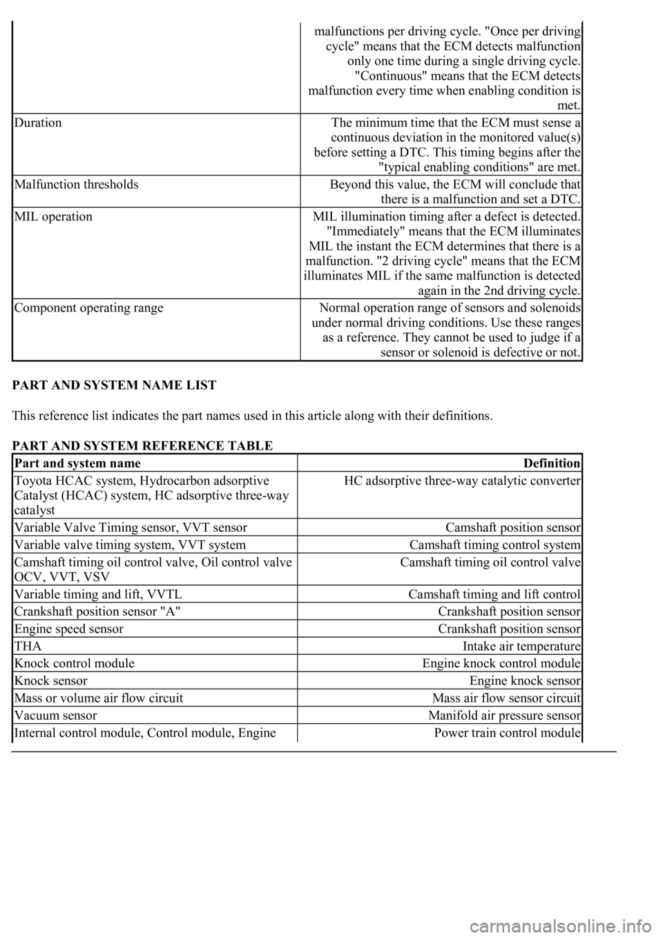
PART AND SYSTEM NAME LIST
This reference list indicates the part names used in this article along with their definitions.
PART AND SYSTEM REFERENCE TABLE
malfunctions per driving cycle. "Once per driving
cycle" means that the ECM detects malfunction
only one time during a single driving cycle.
"Continuous" means that the ECM detects
malfunction every time when enabling condition is
met.
DurationThe minimum time that the ECM must sense a
continuous deviation in the monitored value(s)
before setting a DTC. This timing begins after the
"typical enabling conditions" are met.
Malfunction thresholdsBeyond this value, the ECM will conclude that
there is a malfunction and set a DTC.
MIL operationMIL illumination timing after a defect is detected.
"Immediately" means that the ECM illuminates
MIL the instant the ECM determines that there is a
malfunction. "2 driving cycle" means that the ECM
illuminates MIL if the same malfunction is detected
again in the 2nd driving cycle.
Component operating rangeNormal operation range of sensors and solenoids
under normal driving conditions. Use these ranges
as a reference. They cannot be used to judge if a
sensor or solenoid is defective or not.
Part and system nameDefinition
Toyota HCAC system, Hydrocarbon adsorptive
Catalyst (HCAC) system, HC adsorptive three-way
catalystHC adsorptive three-way catalytic converter
Variable Valve Timing sensor, VVT sensorCamshaft position sensor
Variable valve timing system, VVT systemCamshaft timing control system
Camshaft timing oil control valve, Oil control valve
OCV, VVT, VSVCamshaft timing oil control valve
Variable timing and lift, VVTLCamshaft timing and lift control
Crankshaft position sensor "A"Crankshaft position sensor
Engine speed sensorCrankshaft position sensor
THAIntake air temperature
Knock control moduleEngine knock control module
Knock sensorEngine knock sensor
Mass or volume air flow circuitMass air flow sensor circuit
Vacuum sensorManifold air pressure sensor
Internal control module, Control module, Engine Power train control module
Page 2670 of 4500

control ECU, PCM
FC idleDeceleration fuel cut
Idle air control valveIdle speed control
VSV for CCV, Canister close valve VSV for
canister controlEvaporative emissions canister vent valve
VSV for EVAP, Vacuum switching valve assembly
No. 1, EVAP VAV, Purge VSVEvaporative emissions canister purge valve
VSV for pressure switching valve, Bypass VSVEvaporative emission pressure switching valve
Vapor pressure sensor, EVAP pressure sensor,
Evaporative emission control system pressure
sensorFuel tank pressure sensor
Charcoal canisterEvaporative emissions canister
ORVR systemOn-boad refueling vapor recovery system
Intake manifold runner controlIntake manifold tuning system
Intake manifold runner valve, IMRV, IACV (runner
valve)Intake manifold tuning valve
Intake control VSVIntake manifold tuning solenoid valve
AFSAir fuel ratio sensor
O2 sensorHeater oxygen sensor
Oxygen sensor pumping current circuitOxygen sensor output signal
Oxygen sensor reference ground circuitOxygen sensor signal ground
Accel position sensorAccelerator pedal position sensor
Throttle actuator control motor, Actuator control
motor, Electronic throttle motor, Throttle control
motorElectronic throttle actuator
Electronic throttle control system, Throttle actuator
control systemElectronic throttle control system
Throttle/pedal position sensor, Throttle/pedal
position switch, Throttle position sensor/switchThrottle position sensor
Turbo press sensorTurbocharger pressure sensor
Turbo VSVTurbocharger pressure control solenoid valve
P/S pressure switchPower-steering pressure switch
VSV for ACMActive control engine mount
Speed sensor, Vehicle speed sensor "A", Speed
sensor for skid control ECUVehicle speed sensor
ATF temperature sensor, Trans, fluid temp, sensor,
ATF temperature sensor "A"Transmission fluid temperature sensor
Electronic controlled automatic transmission, ECTElectronically controlled automatic
Intermediate shaft speed sensor "A"Counter gear speed sensor
Part and system nameDefinition
Output speed sensorOutput shaft speed sensor
<002c00510053005800570003005600530048004800470003005600480051005600520055000f0003002c005100530058005700030057005800550045004c005100480003005600530048004800470003005600480051005600520055000300050024000500
0f0003[
Speed sensor (NT), Turbine speed sensorInput turbine speed sensor
Page 2725 of 4500
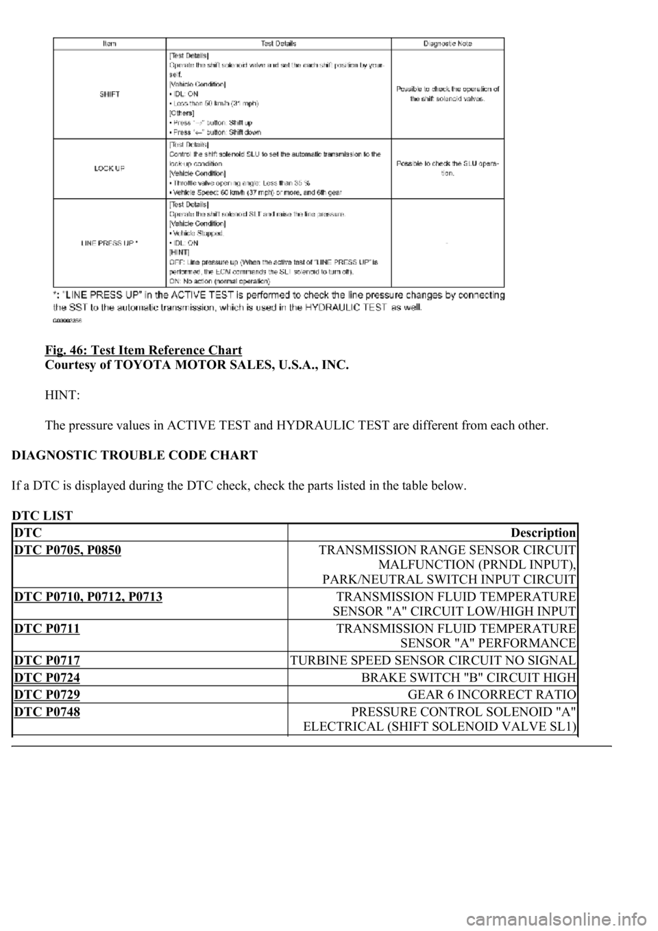
Fig. 46: Test Item Reference Chart
Courtesy of TOYOTA MOTOR SALES, U.S.A., INC.
HINT:
The pressure values in ACTIVE TEST and HYDRAULIC TEST are different from each other.
DIAGNOSTIC TROUBLE CODE CHART
If a DTC is displayed during the DTC check, check the parts listed in the table below.
DTC LIST
DTCDescription
DTC P0705, P0850TRANSMISSION RANGE SENSOR CIRCUIT
MALFUNCTION (PRNDL INPUT),
PARK/NEUTRAL SWITCH INPUT CIRCUIT
DTC P0710, P0712, P0713TRANSMISSION FLUID TEMPERATURE
SENSOR "A" CIRCUIT LOW/HIGH INPUT
DTC P0711TRANSMISSION FLUID TEMPERATURE
SENSOR "A" PERFORMANCE
DTC P0717TURBINE SPEED SENSOR CIRCUIT NO SIGNAL
DTC P0724BRAKE SWITCH "B" CIRCUIT HIGH
DTC P0729GEAR 6 INCORRECT RATIO
DTC P0748PRESSURE CONTROL SOLENOID "A"
ELECTRICAL (SHIFT SOLENOID VALVE SL1)
Page 2740 of 4500
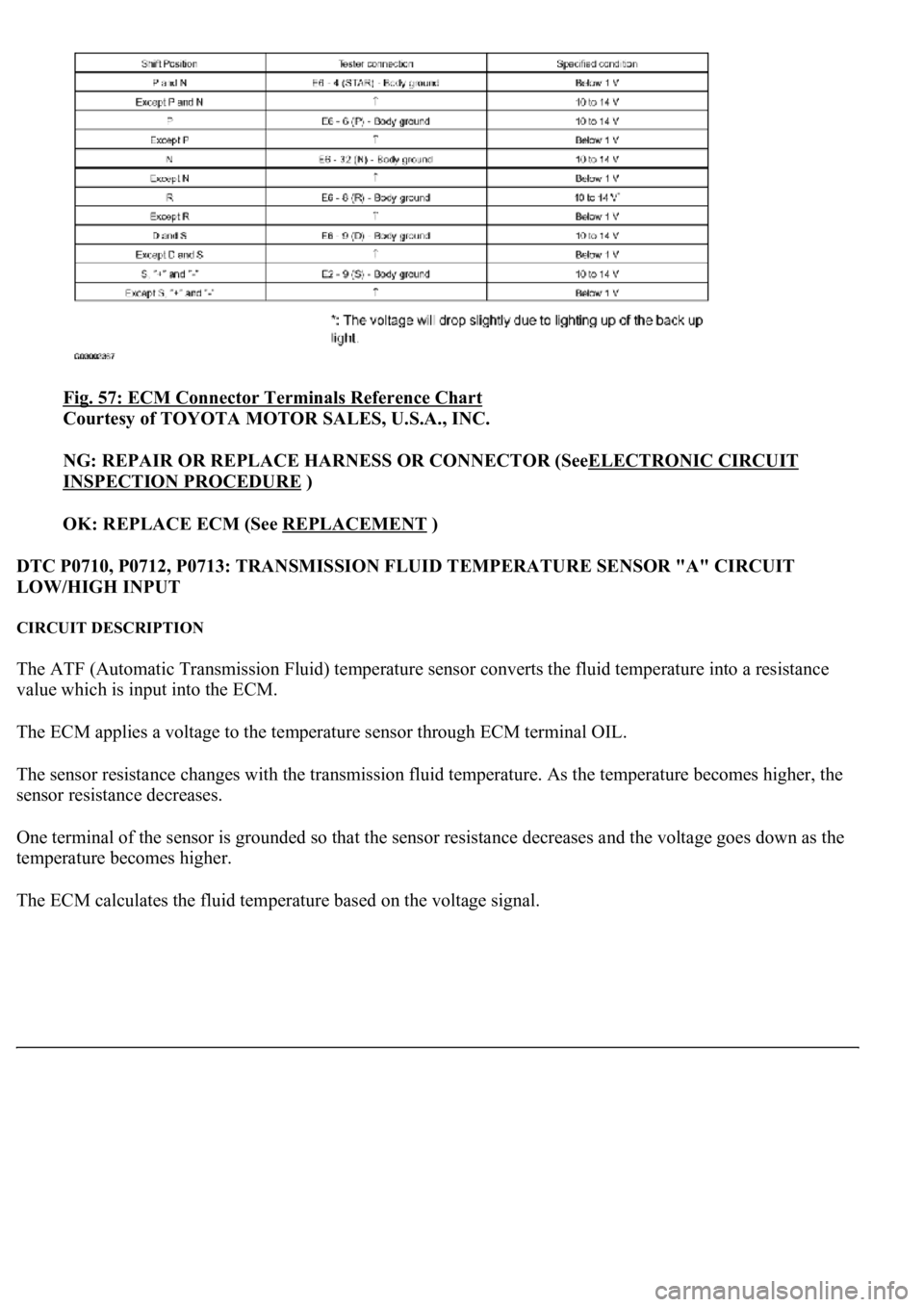
Fig. 57: ECM Connector Terminals Reference Chart
Courtesy of TOYOTA MOTOR SALES, U.S.A., INC.
NG: REPAIR OR REPLACE HARNESS OR CONNECTOR (SeeELECTRONIC CIRCUIT
INSPECTION PROCEDURE )
OK: REPLACE ECM (See REPLACEMENT
)
DTC P0710, P0712, P0713: TRANSMISSION FLUID TEMPERATURE SENSOR "A" CIRCUIT
LOW/HIGH INPUT
CIRCUIT DESCRIPTION
The ATF (Automatic Transmission Fluid) temperature sensor converts the fluid temperature into a resistance
value which is input into the ECM.
The ECM applies a voltage to the temperature sensor through ECM terminal OIL.
The sensor resistance changes with the transmission fluid temperature. As the temperature becomes higher, the
sensor resistance decreases.
One terminal of the sensor is grounded so that the sensor resistance decreases and the voltage goes down as the
temperature becomes higher.
The ECM calculates the fluid temperature based on the volta
ge signal.
Page 2742 of 4500
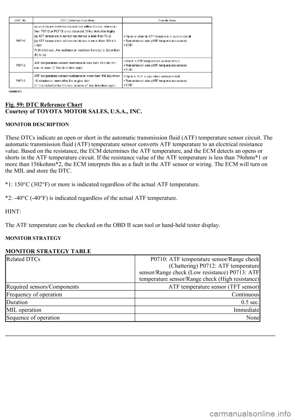
Fig. 59: DTC Reference Chart
Courtesy of TOYOTA MOTOR SALES, U.S.A., INC.
MONITOR DESCRIPTION
These DTCs indicate an open or short in the automatic transmission fluid (ATF) temperature sensor circuit. The
automatic transmission fluid (ATF) temperature sensor converts ATF temperature to an electrical resistance
value. Based on the resistance, the ECM determines the ATF temperature, and the ECM detects an opens or
shorts in the ATF temperature circuit. If the resistance value of the ATF temperature is less than 79ohms*1 or
more than 156kohms*2, the ECM interprets this as a fault in the ATF sensor or wiring. The ECM will turn on
the MIL and store the DTC.
*1: 150°C (302°F) or more is indicated regardless of the actual ATF temperature.
*2: -40°C (-40°F) is indicated regardless of the actual ATF temperature.
HINT:
The ATF temperature can be checked on the OBD II scan tool or hand-held tester display.
MONITOR STRATEGY
MONITOR STRATEGY TABLE
Related DTCsP0710: ATF temperature sensor/Range check
(Chattering) P0712: ATF temperature
sensor/Range check (Low resistance) P0713: ATF
temperature sensor/Range check (High resistance)
Required sensors/ComponentsATF temperature sensor (TFT sensor)
Frequency of operationContinuous
Duration0.5 sec.
MIL operationImmediate
Sequence of operationNone
Page 2743 of 4500
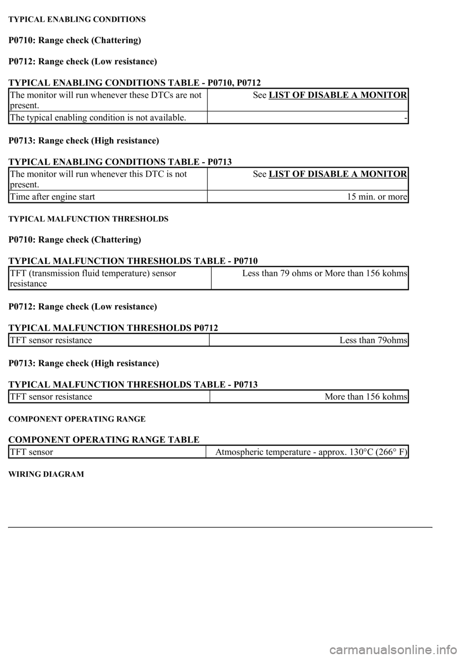
TYPICAL ENABLING CONDITIONS
P0710: Range check (Chattering)
P0712: Range check (Low resistance)
TYPICAL ENABLING CONDITIONS TABLE - P0710, P0712
P0713: Range check (High resistance)
TYPICAL ENABLING CONDITIONS TABLE - P0713
TYPICAL MALFUNCTION THRESHOLDS
P0710: Range check (Chattering)
TYPICAL MALFUNCTION THRESHOLDS TABLE - P0710
P0712: Range check (Low resistance)
TYPICAL MALFUNCTION THRESHOLDS P0712
P0713: Range check (High resistance)
TYPICAL MALFUNCTION THRESHOLDS TABLE - P0713
COMPONENT OPERATING RANGE
COMPONENT OPERATING RANGE TABLE
WIRING DIAGRAM
The monitor will run whenever these DTCs are not
present.See LIST OF DISABLE A MONITOR
The typical enabling condition is not available.-
The monitor will run whenever this DTC is not
present.See LIST OF DISABLE A MONITOR
Time after engine start15 min. or more
TFT (transmission fluid temperature) sensor
resistanceLess than 79 ohms or More than 156 kohms
TFT sensor resistanceLess than 79ohms
TFT sensor resistanceMore than 156 kohms
TFT sensorAtmospheric temperature - approx. 130°C (266° F)
Page 2745 of 4500
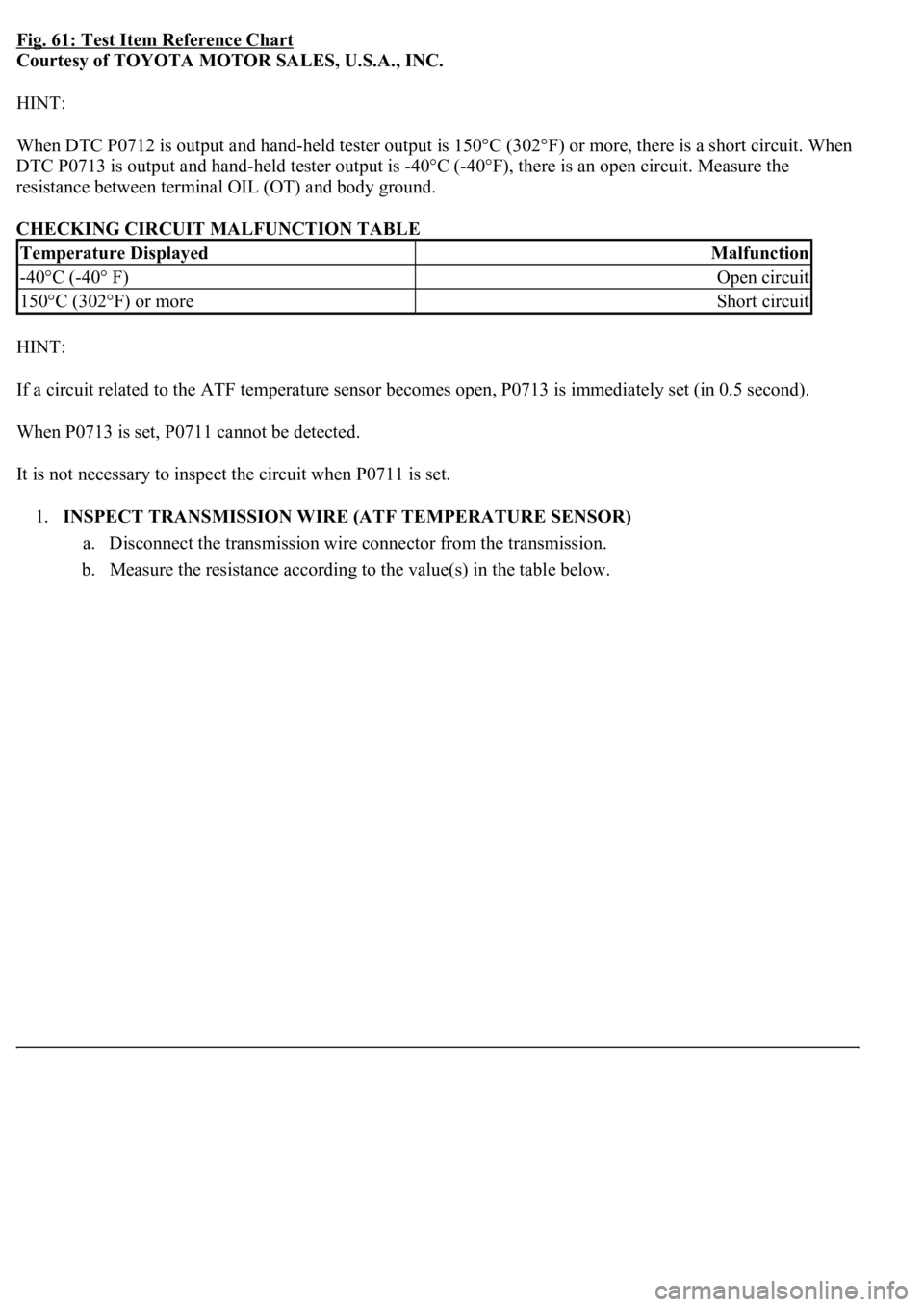
Fig. 61: Test Item Reference Chart
Courtesy of TOYOTA MOTOR SALES, U.S.A., INC.
HINT:
<003a004b004800510003002700370026000300330013001a001400150003004c0056000300520058005700530058005700030044005100470003004b0044005100470010004b0048004f004700030057004800560057004800550003005200580057005300
5800570003004c00560003001400180013008300260003000b[302°F) or more, there is a short circuit. When
DTC P0713 is output and hand-held tester output is -40°C (-40°F), there is an open circuit. Measure the
resistance between terminal OIL (OT) and body ground.
CHECKING CIRCUIT MALFUNCTION TABLE
HINT:
If a circuit related to the ATF temperature sensor becomes open, P0713 is immediately set (in 0.5 second).
When P0713 is set, P0711 cannot be detected.
It is not necessary to inspect the circuit when P0711 is set.
1.INSPECT TRANSMISSION WIRE (ATF TEMPERATURE SENSOR)
a. Disconnect the transmission wire connector from the transmission.
b. Measure the resistance according to the value(s) in the table below.
Temperature DisplayedMalfunction
-40°C (-40° F)Open circuit
150°C (302°F) or moreShort circuit
Page 2746 of 4500
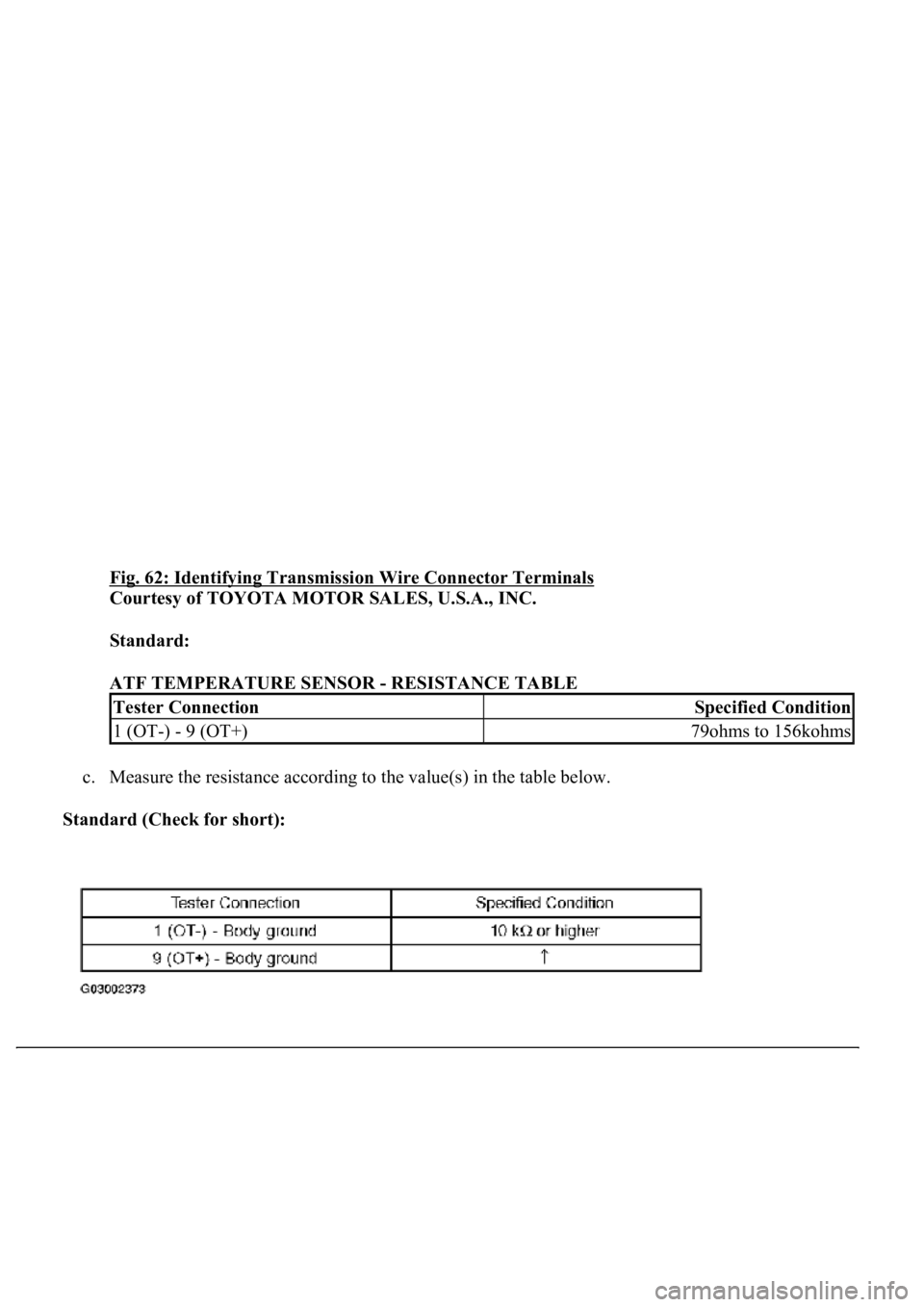
Fig. 62: Identifying Transmission Wire Connector Terminals
Courtesy of TOYOTA MOTOR SALES, U.S.A., INC.
Standard:
ATF TEMPERATURE SENSOR - RESISTANCE TABLE
c. Measure the resistance according to the value(s) in the table below.
Standard (Check for short):
Tester ConnectionSpecified Condition
1 (OT-) - 9 (OT+)79ohms to 156kohms
Page 2748 of 4500
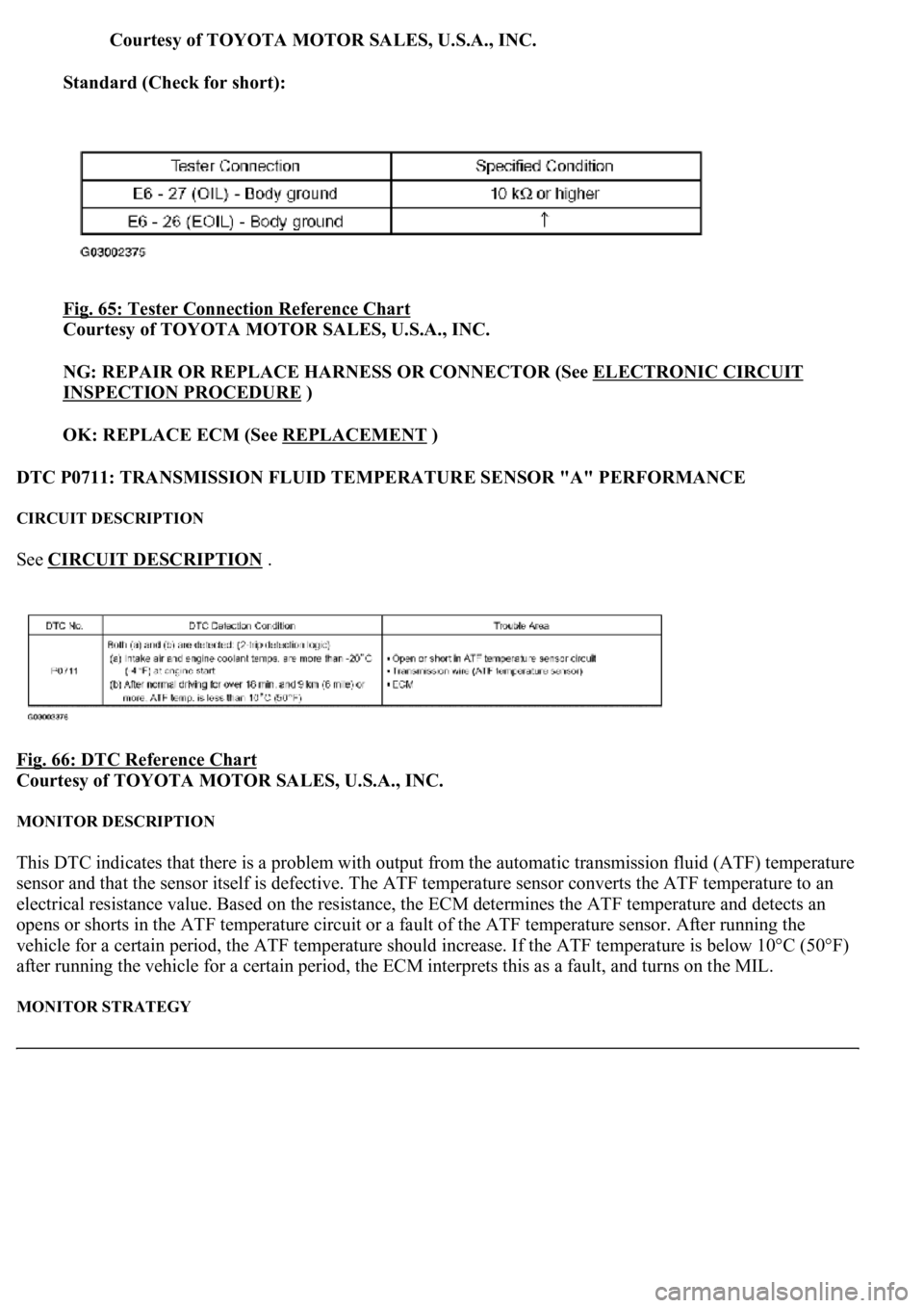
Courtesy of TOYOTA MOTOR SALES, U.S.A., INC.
Standard (Check for short):
Fig. 65: Tester Connection Reference Chart
Courtesy of TOYOTA MOTOR SALES, U.S.A., INC.
NG: REPAIR OR REPLACE HARNESS OR CONNECTOR (See ELECTRONIC CIRCUIT
INSPECTION PROCEDURE )
OK: REPLACE ECM (See REPLACEMENT
)
DTC P0711: TRANSMISSION FLUID TEMPERATURE SENSOR "A" PERFORMANCE
CIRCUIT DESCRIPTION
See CIRCUIT DESCRIPTION .
Fig. 66: DTC Reference Chart
Courtesy of TOYOTA MOTOR SALES, U.S.A., INC.
MONITOR DESCRIPTION
This DTC indicates that there is a problem with output from the automatic transmission fluid (ATF) temperature
sensor and that the sensor itself is defective. The ATF temperature sensor converts the ATF temperature to an
electrical resistance value. Based on the resistance, the ECM determines the ATF temperature and detects an
opens or shorts in the ATF temperature circuit or a fault of the ATF temperature sensor. After running the
vehicle for a certain period, the ATF temperature should increase. If the ATF temperature is below 10°C (50°F)
after running the vehicle for a certain period, the ECM interprets this as a fault, and turns on the MIL.
MONITOR STRATEGY
Page 2749 of 4500
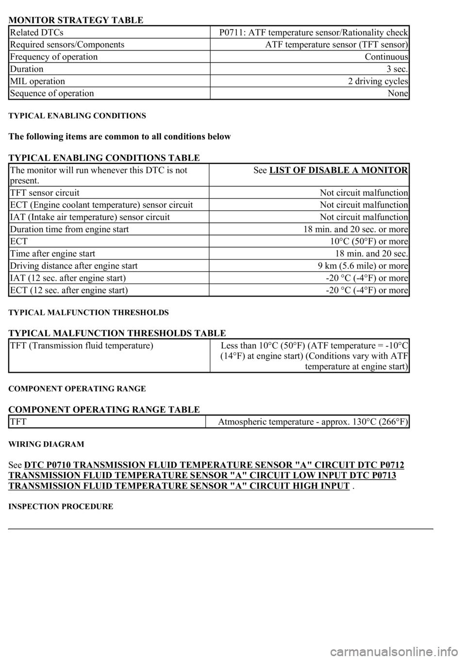
MONITOR STRATEGY TABLE
TYPICAL ENABLING CONDITIONS
The following items are common to all conditions below
TYPICAL ENABLING CONDITIONS TABLE
TYPICAL MALFUNCTION THRESHOLDS
TYPICAL MALFUNCTION THRESHOLDS TABLE
COMPONENT OPERATING RANGE
COMPONENT OPERATING RANGE TABLE
WIRING DIAGRAM
See DTC P0710 TRANSMISSION FLUID TEMPERATURE SENSOR "A" CIRCUIT DTC P0712
TRANSMISSION FLUID TEMPERATURE SENSOR "A" CIRCUIT LOW INPUT DTC P0713
TRANSMISSION FLUID TEMPERATURE SENSOR "A" CIRCUIT HIGH INPUT .
INSPECTION PROCEDURE
Related DTCsP0711: ATF temperature sensor/Rationality check
Required sensors/ComponentsATF temperature sensor (TFT sensor)
Frequency of operationContinuous
Duration3 sec.
MIL operation2 driving cycles
Sequence of operationNone
The monitor will run whenever this DTC is not
present.See LIST OF DISABLE A MONITOR
TFT sensor circuitNot circuit malfunction
ECT (Engine coolant temperature) sensor circuitNot circuit malfunction
IAT (Intake air temperature) sensor circuitNot circuit malfunction
Duration time from engine start18 min. and 20 sec. or more
ECT10°C (50°F) or more
Time after engine start18 min. and 20 sec.
Driving distance after engine start9 km (5.6 mile) or more
IAT (12 sec. after engine start)-20 °C (-4°F) or more
ECT (12 sec. after engine start)-20 °C (-4°F) or more
TFT (Transmission fluid temperature)Less than 10°C (50°F) (ATF temperature = -10°C
(14°F) at engine start) (Conditions vary with ATF
temperature at engine start)
TFTAtmospheric temperature - approx. 130°C (266°F)