LEXUS LS430 2003 Factory Workshop Manual
LS430 2003
LEXUS
LEXUS
https://www.carmanualsonline.info/img/36/57050/w960_57050-0.png
LEXUS LS430 2003 Factory Workshop Manual
Page 2877 of 4500

SHIFT SOLENOID VALVE (SLU) - RESISTANCE TABLE
c. Connect the positive (+) lead with a 21 W bulb to terminal 2 and the negative (-) lead to terminal 1
of the solenoid valve connector, then check the movement of the valve.
OK:
The solenoid makes an operating noise.
NG: REPLACE SHIFT SOLENOID VALVE (SLU)
OK: Go to next step
3.INSPECT TRANSMISSION VALVE BODY ASSY (See chapter 2 in PROBLEM SYMPTOMS
TABLE )
OK:
There are no foreign objects on each valve and they operate smoothly.
NG: REPAIR OR REPLACE TRANSMISSION VALVE BODY ASSY (See step 6 on
REPLACEMENT
)
OK: Go to next step
4.INSPECT TORQUE CONVERTER CLUTCH ASSY (See INSPECTION
)
OK:
The torque converter clutch operates normally.
NG: REPLACE TORQUE CONVERTER CLUTCH ASSY
OK: REPAIR OR REPLACE AUTOMATIC TRANSMISSION ASSY (See COMPONENTS
)
DTC P2759: TORQUE CONVERTER CLUTCH PRESSURE CONTROL SOLENOID CONTROL
CIRCUIT ELECTRICAL (SHIFT SOLENOID VALVE SLU)
CIRCUIT DESCRIPTION
The amount of current flow to the solenoid is controlled by the (*) duty ratio of the ECM output signal. The
hi
gher the duty ratio becomes, the higher the lock-up hydraulic pressure becomes during the lock-up operation.
Tester ConnectionSpecified Condition 20°C (68°F)
1 - 25.0 to 5.6 ohms
Page 2922 of 4500
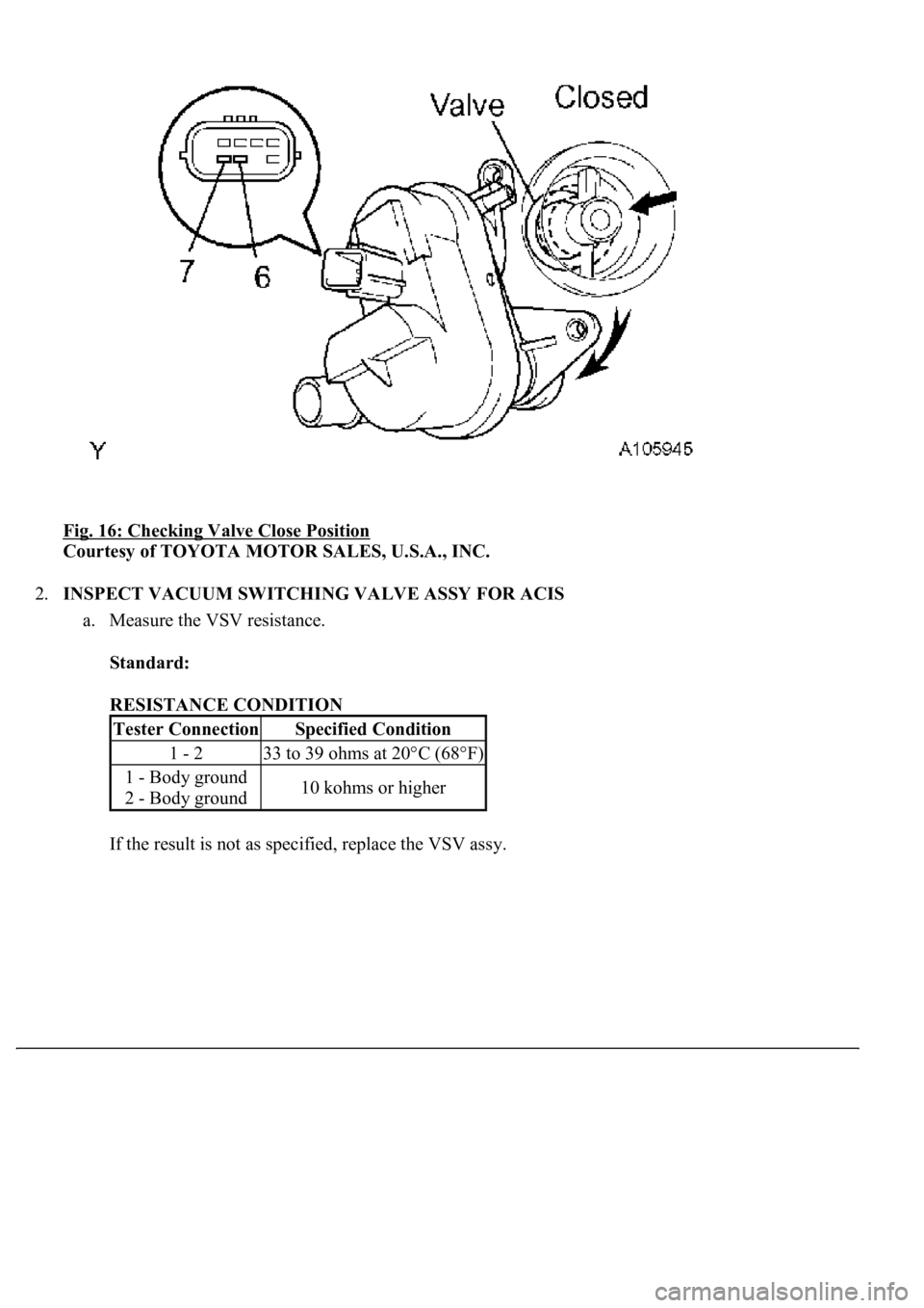
Fig. 16: Checking Valve Close Position
Courtesy of TOYOTA MOTOR SALES, U.S.A., INC.
2.INSPECT VACUUM SWITCHING VALVE ASSY FOR ACIS
a. Measure the VSV resistance.
Standard:
RESISTANCE CONDITION
If the result is not as specified, replace the VSV ass
y.
Tester ConnectionSpecified Condition
1 - 233 to 39 ohms at 20°C (68°F)
1 - Body ground
2 - Body ground10 kohms or higher
Page 2925 of 4500
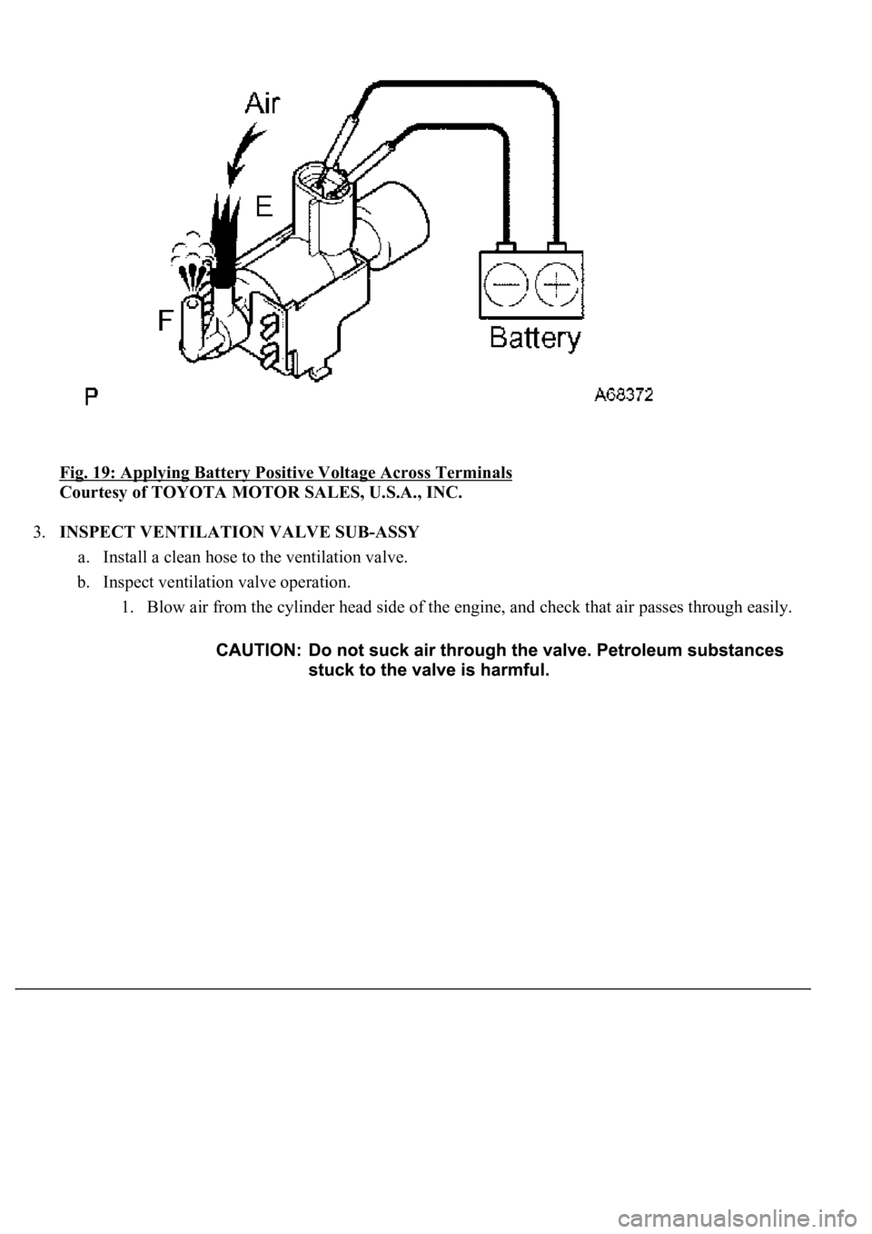
Fig. 19: Applying Battery Positive Voltage Across Terminals
Courtesy of TOYOTA MOTOR SALES, U.S.A., INC.
3.INSPECT VENTILATION VALVE SUB-ASSY
a. Install a clean hose to the ventilation valve.
b. Inspect ventilation valve operation.
1. Blow air from the cylinder head side of the engine, and check that air passes through easily.
Page 2926 of 4500
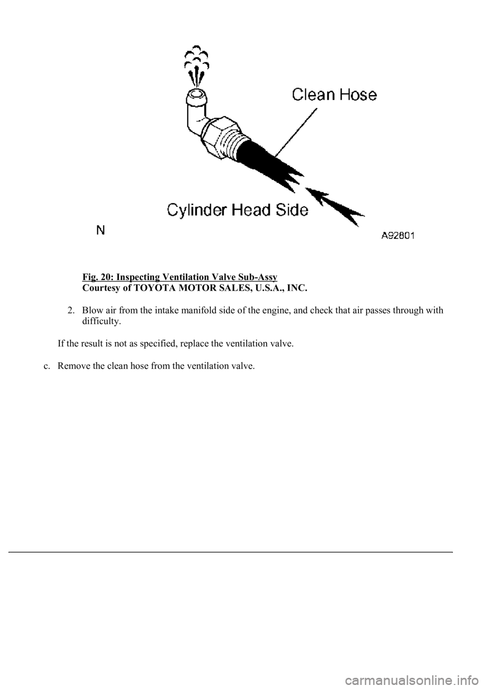
Fig. 20: Inspecting Ventilation Valve Sub-Assy
Courtesy of TOYOTA MOTOR SALES, U.S.A., INC.
2. Blow air from the intake manifold side of the engine, and check that air passes through with
difficulty.
If the result is not as specified, replace the ventilation valve.
c. Remove the clean hose from the ventilation valve.
Page 2931 of 4500
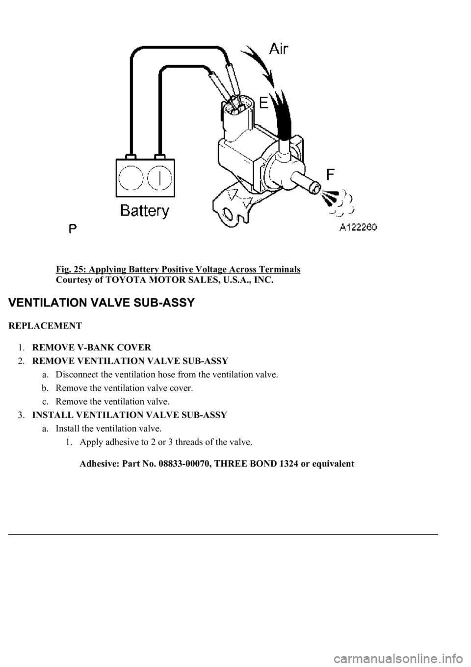
Fig. 25: Applying Battery Positive Voltage Across Terminals
Courtesy of TOYOTA MOTOR SALES, U.S.A., INC.
REPLACEMENT
1.REMOVE V-BANK COVER
2.REMOVE VENTILATION VALVE SUB-ASSY
a. Disconnect the ventilation hose from the ventilation valve.
b. Remove the ventilation valve cover.
c. Remove the ventilation valve.
3.INSTALL VENTILATION VALVE SUB-ASSY
a. Install the ventilation valve.
1. Apply adhesive to 2 or 3 threads of the valve.
Adhesive: Part No. 08833-00070, THREE BOND 1324 or equivalent
Page 2945 of 4500
Standard: 0.6 to 1.0 V
If the result is not as specified, replace the accelerator pedal position sensor.
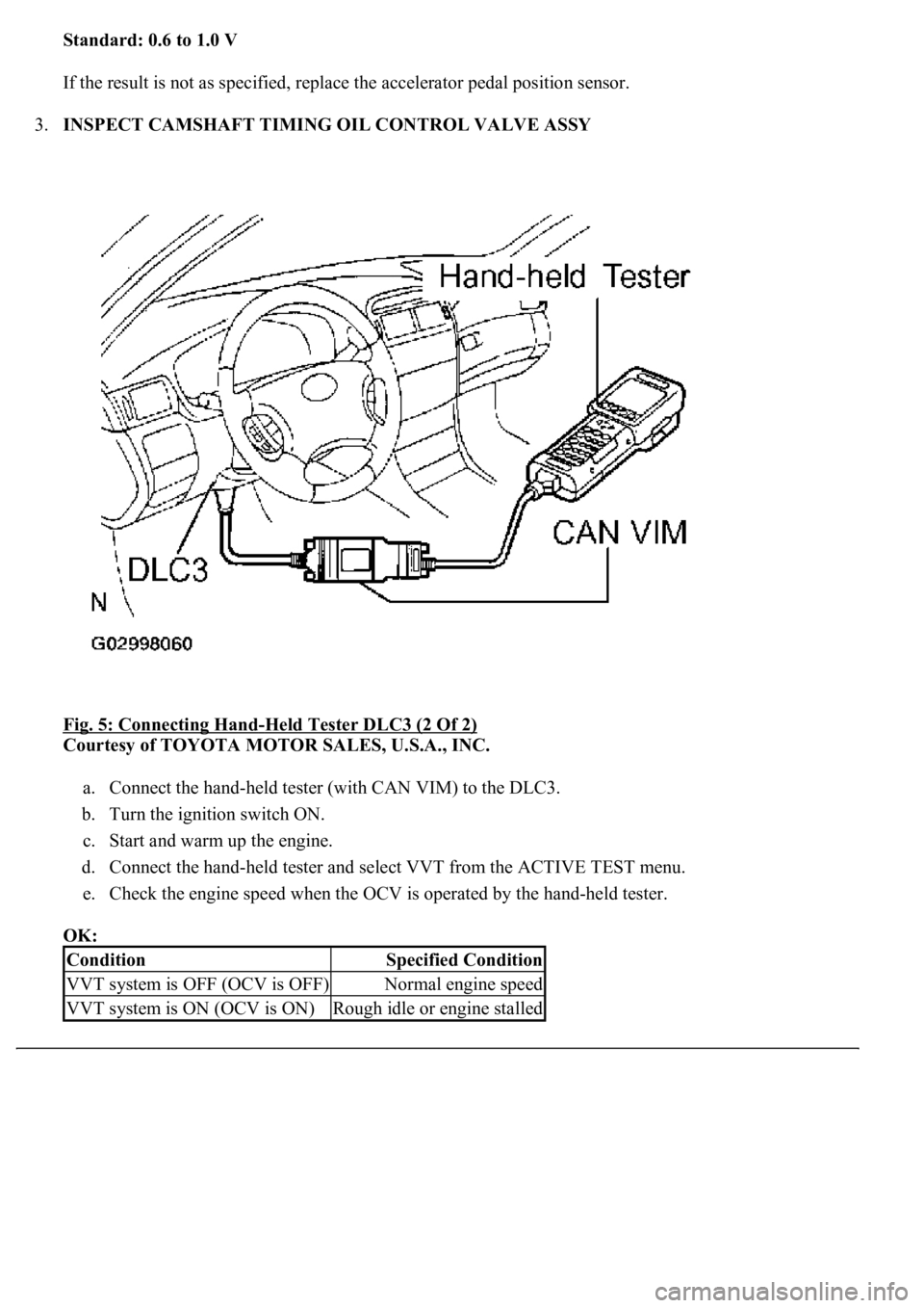
3.INSPECT CAMSHAFT TIMING OIL CONTROL VALVE ASSY
Fig. 5: Connecting Hand
-Held Tester DLC3 (2 Of 2)
Courtesy of TOYOTA MOTOR SALES, U.S.A., INC.
a. Connect the hand-held tester (with CAN VIM) to the DLC3.
b. Turn the ignition switch ON.
c. Start and warm up the engine.
d. Connect the hand-held tester and select VVT from the ACTIVE TEST menu.
e. Check the engine speed when the OCV is operated by the hand-held tester.
OK:
ConditionSpecified Condition
VVT system is OFF (OCV is OFF)Normal engine speed
VVT system is ON (OCV is ON)Rough idle or engine stalled
Page 2947 of 4500
Courtesy of TOYOTA MOTOR SALES, U.S.A., INC.
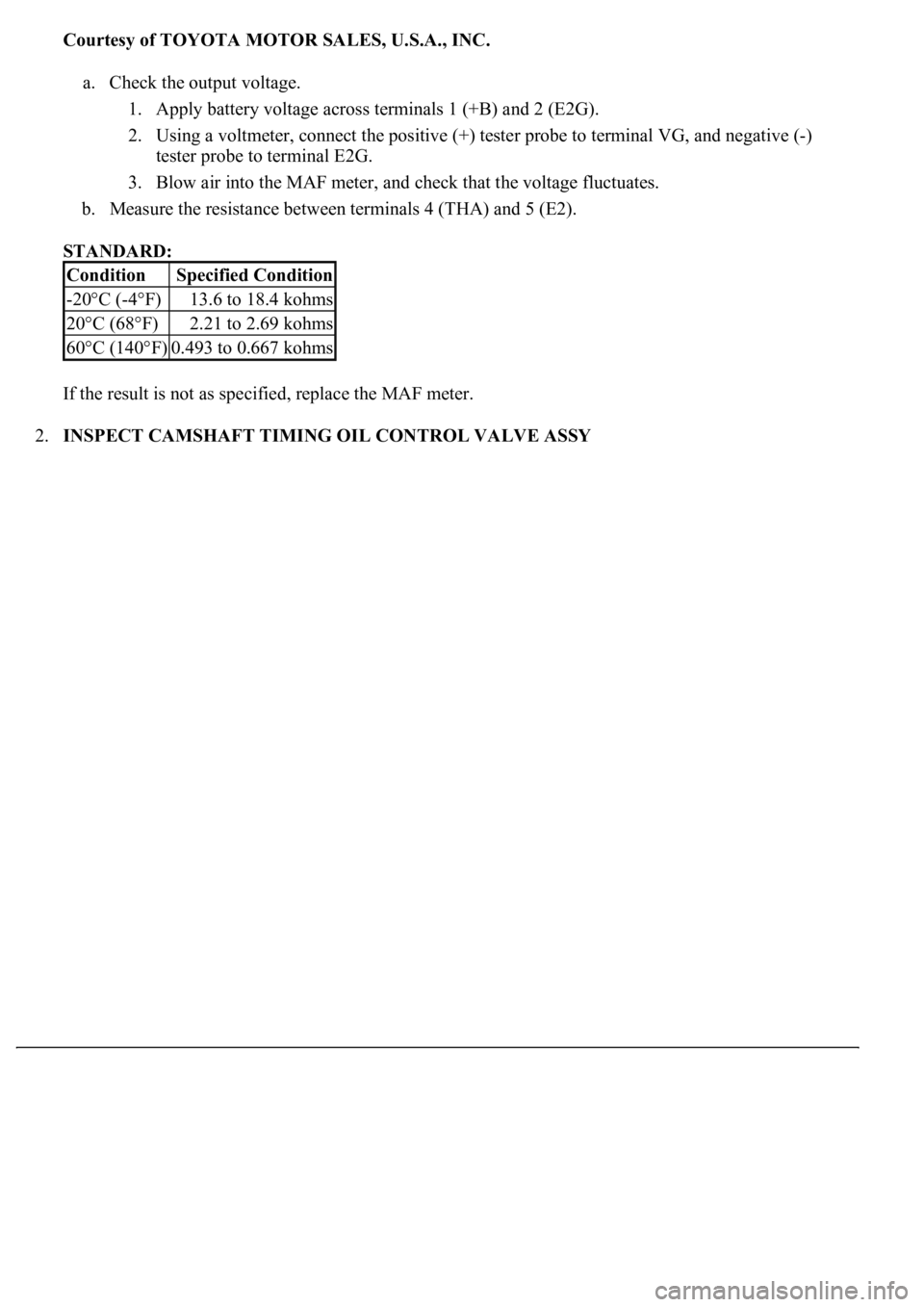
a. Check the output voltage.
1. Apply battery voltage across terminals 1 (+B) and 2 (E2G).
2. Using a voltmeter, connect the positive (+) tester probe to terminal VG, and negative (-)
tester probe to terminal E2G.
3. Blow air into the MAF meter, and check that the voltage fluctuates.
b. Measure the resistance between terminals 4 (THA) and 5 (E2).
STANDARD:
If the result is not as specified, replace the MAF meter.
2.INSPECT CAMSHAFT TIMING OIL CONTROL VALVE ASSY
ConditionSpecified Condition
-20°C (-4°F)13.6 to 18.4 kohms
20°C (68°F)2.21 to 2.69 kohms
60°C (140°F)0.493 to 0.667 kohms
Page 2948 of 4500
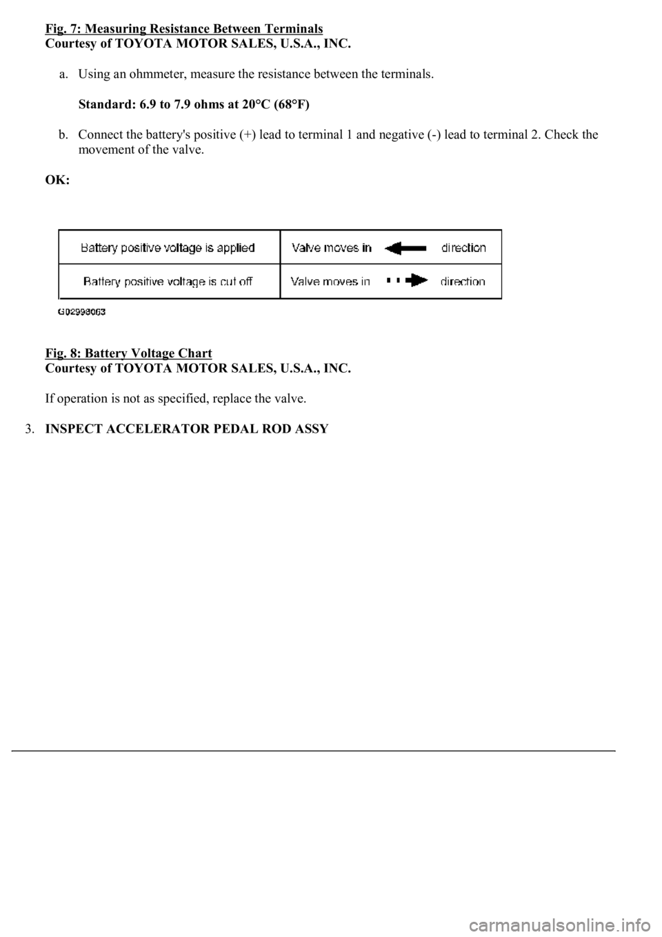
Fig. 7: Measuring Resistance Between Terminals
Courtesy of TOYOTA MOTOR SALES, U.S.A., INC.
a. Using an ohmmeter, measure the resistance between the terminals.
Standard: 6.9 to 7.9 ohms at 20°C (68°F)
b. Connect the battery's positive (+) lead to terminal 1 and negative (-) lead to terminal 2. Check the
movement of the valve.
OK:
Fig. 8: Battery Voltage Chart
Courtesy of TOYOTA MOTOR SALES, U.S.A., INC.
If operation is not as specified, replace the valve.
3.INSPECT ACCELERATOR PEDAL ROD ASSY
Page 2973 of 4500
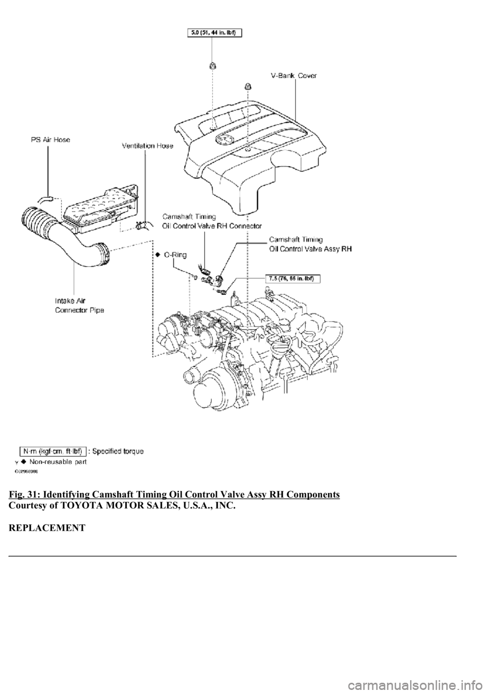
Fig. 31: Identifying Camshaft Timing Oil Control Valve Assy RH Components
Courtesy of TOYOTA MOTOR SALES, U.S.A., INC.
REPLACEMENT
Page 2974 of 4500
1.REMOVE V-BANK COVER
a. Remove the 2 nuts and V-bank cover.
2.REMOVE AIR CLEANER INLET NO.1
3.REMOVE INTAKE AIR CONNECTOR PIPE
a. Disconnect the air hose and ventilation hose.
b. Remove the bolt.
c. Loosen the 2 hose clamps and remove the intake air connector pipe.
4.REMOVE CAMSHAFT TIMING OIL CONTROL VALVE ASSY RH
a. Disconnect the oil control valve connector.
b. Remove the bolts and oil control valve.
5.INSTALL CAMSHAFT TIMING OIL CONTROL VALVE ASSY RH
a. Install the oil control valve with the bolt.
Torque: 7.5 N.m (76 kgf.cm, 66 in..lbf)
b. Connect the oil control valve connector.
6.INSTALL INTAKE AIR CONNECTOR PIPE
a. Install the intake air connector pipe with the bolt and 2 hose clamps.
Torque:
4.0 N.m (41 kgf.cm, 35 in..lbf) for hose clamp
5.0 N.m (51 kgf.cm, 44 in..lbf) for bolt
7.INSTALL AIR CLEANER INLET NO.1
8.INSTALL V-BANK COVER
Torque: 5.0 N.m (51 kgf.cm, 44 in..lbf)
COMPONENTS