LEXUS LS430 2003 Factory Manual PDF
LS430 2003
LEXUS
LEXUS
https://www.carmanualsonline.info/img/36/57050/w960_57050-0.png
LEXUS LS430 2003 Factory Manual PDF
Page 2975 of 4500
Fig. 32: Identifying Camshaft Timing Oil Control Valve Assy LH Components
Courtesy of TOYOTA MOTOR SALES, U.S.A., INC.
REPLACEMENT
Page 2976 of 4500
1.REMOVE V-BANK COVER
a. Remove the 2 nuts and V-bank cover.
2.REMOVE CAMSHAFT TIMING OIL CONTROL VALVE ASSY LH
a. Disconnect the oil control valve connector.
b. Remove the bolts and oil control valve.
3.INSTALL CAMSHAFT TIMING OIL CONTROL VALVE ASSY LH
a. Install the oil control valve with the bolt.
Torque: 7.5 N.m (76 kgf.cm, 66 in..lbf)
b. Connect the oil control valve connector.
4.INSTALL V-BANK COVER
Torque: 5.0 N.m (51 kgf.cm, 44 in..lbf)
COMPONENTS
Page 3295 of 4500
Courtesy of TOYOTA MOTOR SALES, U.S.A., INC.
6.REMOVE CAMSHAFT (See REPLACEMENT
)
7.REMOVE NO.3 CAMSHAFT SUB-ASSY (See REPLACEMENT
)
8.ADJUST VALVE CLEARANCE
a. Using a powerful magnet, remove the valve lifter and adjusting shim.
Fig. 15: Identifying Powerful Magnet
Courtesy of TOYOTA MOTOR SALES, U.S.A., INC.
b. Determine the replacement adjusting shim size according to these formulas and charts:
1. Using a micrometer, measure the thickness of the removed shim.
2. Calculate the thickness of a new shim so that the valve clearance comes within the specified
value.
Page 3327 of 4500
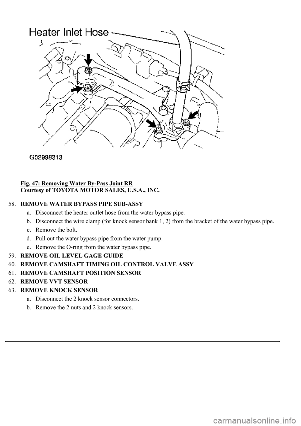
Fig. 47: Removing Water By-Pass Joint RR
Courtesy of TOYOTA MOTOR SALES, U.S.A., INC.
58.REMOVE WATER BYPASS PIPE SUB-ASSY
a. Disconnect the heater outlet hose from the water bypass pipe.
b. Disconnect the wire clamp (for knock sensor bank 1, 2) from the bracket of the water bypass pipe.
c. Remove the bolt.
d. Pull out the water bypass pipe from the water pump.
e. Remove the O-ring from the water bypass pipe.
59.REMOVE OIL LEVEL GAGE GUIDE
60.REMOVE CAMSHAFT TIMING OIL CONTROL VALVE ASSY
61.REMOVE CAMSHAFT POSITION SENSOR
62.REMOVE VVT SENSOR
63.REMOVE KNOCK SENSOR
a. Disconnect the 2 knock sensor connectors.
b. Remove the 2 nuts and 2 knock sensors.
Page 3339 of 4500
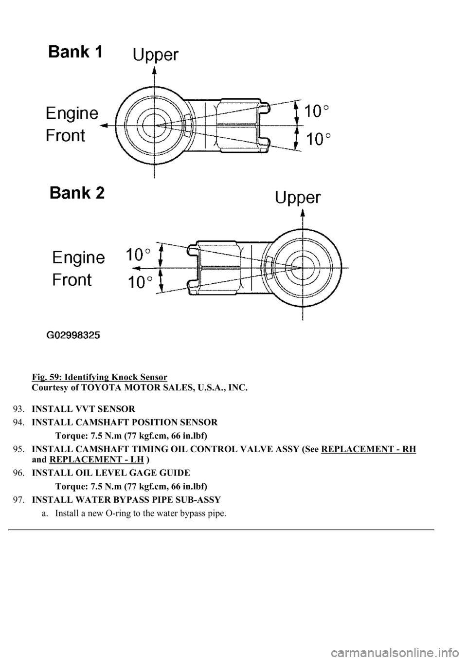
Fig. 59: Identifying Knock Sensor
Courtesy of TOYOTA MOTOR SALES, U.S.A., INC.
93.INSTALL VVT SENSOR
94.INSTALL CAMSHAFT POSITION SENSOR
Torque: 7.5 N.m (77 kgf.cm, 66 in.lbf)
95.INSTALL CAMSHAFT TIMING OIL CONTROL VALVE ASSY (See REPLACEMENT
- RH
and REPLACEMENT
- LH )
96.INSTALL OIL LEVEL GAGE GUIDE
Torque: 7.5 N.m (77 kgf.cm, 66 in.lbf)
97.INSTALL WATER BYPASS PIPE SUB-ASSY
a. Install a new O-rin
g to the water bypass pipe.
Page 3381 of 4500
<0029004c004a00110003001400130013001d00030036004800570057004c0051004a00030037004c0050004c0051004a0003003000440055004e00030032004900030026004400500056004b004400490057000300300044004c00510003002a0048004400
55[
Courtesy of TOYOTA MOTOR SALES, U.S.A., INC.
4. Uniformly loosen the 22 bearing cap bolts in several passes in the sequence shown in the
illustration.
5. Remove the 22 bearing cap bolts, 4 seal washers, oil feed pipe, 9 bearing caps, camshaft housing
plug, oil control valve filter and 2 camshafts.
25.REMOVE NO.3 CAMSHAFT SUB-ASSY
Page 3458 of 4500
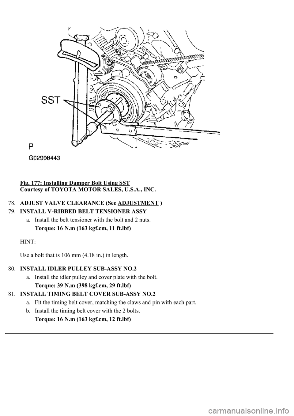
Fig. 177: Installing Damper Bolt Using SST
Courtesy of TOYOTA MOTOR SALES, U.S.A., INC.
78.ADJUST VALVE CLEARANCE (See ADJUSTMENT
)
79.INSTALL V-RIBBED BELT TENSIONER ASSY
a. Install the belt tensioner with the bolt and 2 nuts.
Torque: 16 N.m (163 kgf.cm, 11 ft.lbf)
HINT:
Use a bolt that is 106 mm (4.18 in.) in length.
80.INSTALL IDLER PULLEY SUB-ASSY NO.2
a. Install the idler pulley and cover plate with the bolt.
Torque: 39 N.m (398 kgf.cm, 29 ft.lbf)
81.INSTALL TIMING BELT COVER SUB-ASSY NO.2
a. Fit the timing belt cover, matching the claws and pin with each part.
b. Install the timing belt cover with the 2 bolts.
Torque: 16 N.m (163 kgf.cm, 12 ft.lbf)
Page 3496 of 4500
46.INSTALL OIL COOLER OUTLET TUBE NO.1
47.INSTALL OIL COOLER INLET TUBE NO.
48.INSTALL AIR CLEANER INLET NO.1
Torque: 5.0 N.m (51 kgf.cm, 44 in.lbf)
49.INSTALL INTAKE AIR CONNECTOR PIPE
Torque: 5.0 N.m (51 kgf.cm, 44 in.lbf)
50.INSTALL V-BANK COVER
Torque: 5.0 N.m (51 kgf.cm, 44 in.lbf)
51.REFILL ENGINE COOLANT (See REPLACEMENT
)
52.CHECK FOR ENGINE COOLANT LEAKS (See ON
-VEHICLE INSPECTION )
53.INSTALL ENGINE UNDER COVER NO.1
54.CONNECT BATTERY NEGATIVE TERMINAL
REPLACEMENT
1.REMOVE TIMING BELT (See REPLACEMENT
)
2.REMOVE CYLINDER HEAD COVER SUB-ASSY (See REPLACEMENT
)
3.PISTON & VALVE BREAK PREVENT WORK
a. Turn the crankshaft timing pulley counterclockwise by 45° and match the cut part with the
illustrated position.
HINT:
When the No. 1 cylinder is positioned at 45° BTDC, the valve and piston do not interfere with each other
even when the valve is fully open.
Page 3498 of 4500
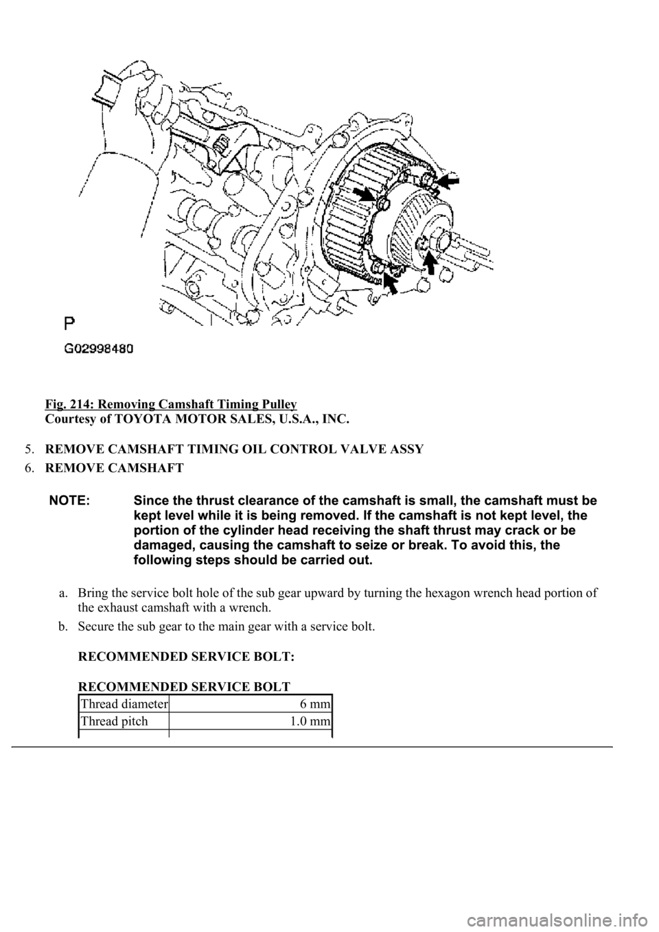
Fig. 214: Removing Camshaft Timing Pulley
Courtesy of TOYOTA MOTOR SALES, U.S.A., INC.
5.REMOVE CAMSHAFT TIMING OIL CONTROL VALVE ASSY
6.REMOVE CAMSHAFT
a. Bring the service bolt hole of the sub gear upward by turning the hexagon wrench head portion of
the exhaust camshaft with a wrench.
b. Secure the sub gear to the main gear with a service bolt.
RECOMMENDED SERVICE BOLT:
RECOMMENDED SERVICE BOLT
Thread diameter6 mm
Thread pitch1.0 mm
Page 3524 of 4500
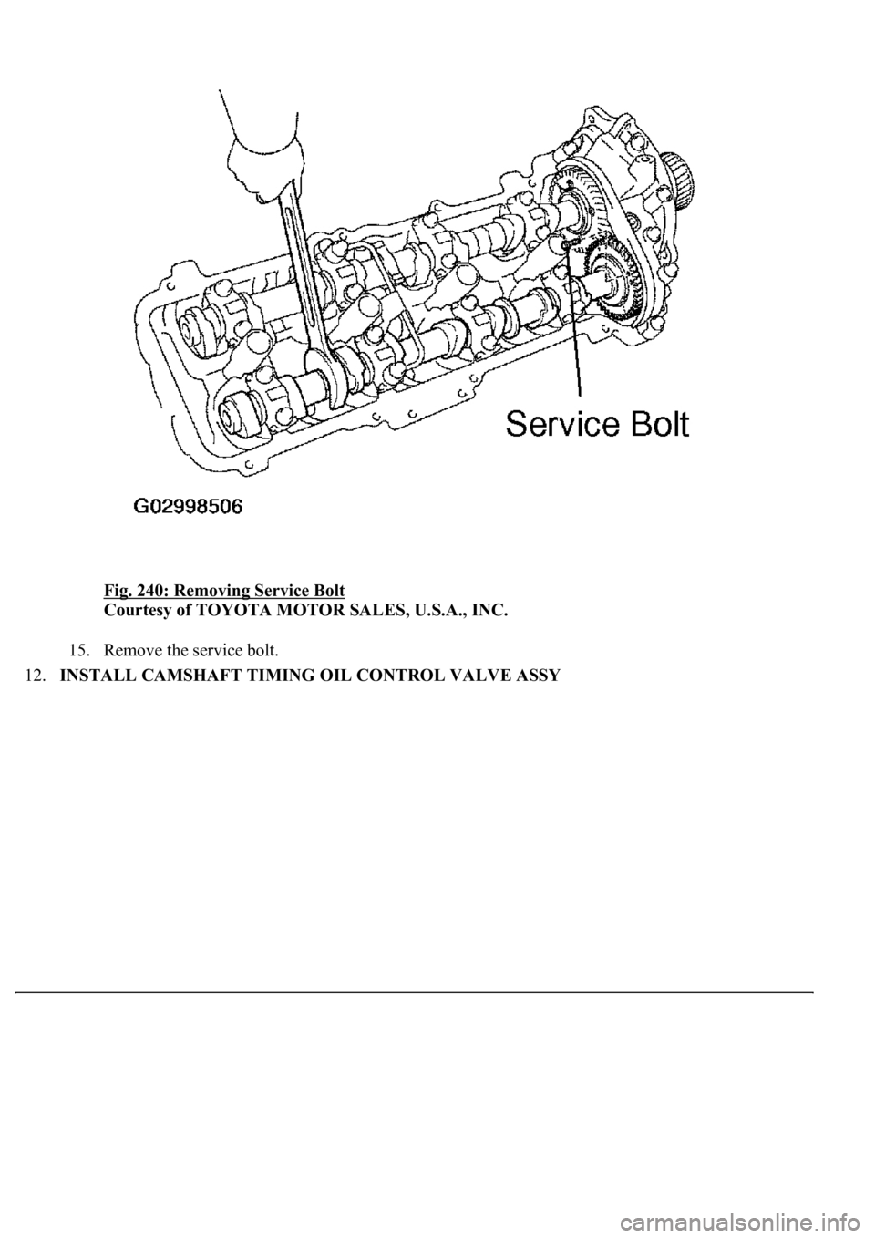
Fig. 240: Removing Service Bolt
Courtesy of TOYOTA MOTOR SALES, U.S.A., INC.
15. Remove the service bolt.
12.INSTALL CAMSHAFT TIMING OIL CONTROL VALVE ASSY