LEXUS LS430 2003 Factory Manual PDF
LS430 2003
LEXUS
LEXUS
https://www.carmanualsonline.info/img/36/57050/w960_57050-0.png
LEXUS LS430 2003 Factory Manual PDF
Page 3527 of 4500
Fig. 243: Removing Camshaft Timing Pulley Sub-Assy LH
Courtesy of TOYOTA MOTOR SALES, U.S.A., INC.
HINT:
When the No. 1 cylinder is positioned at 45° BTDC, the valve and piston do not interfere with each
other even when the valve is fully open.
Page 3528 of 4500
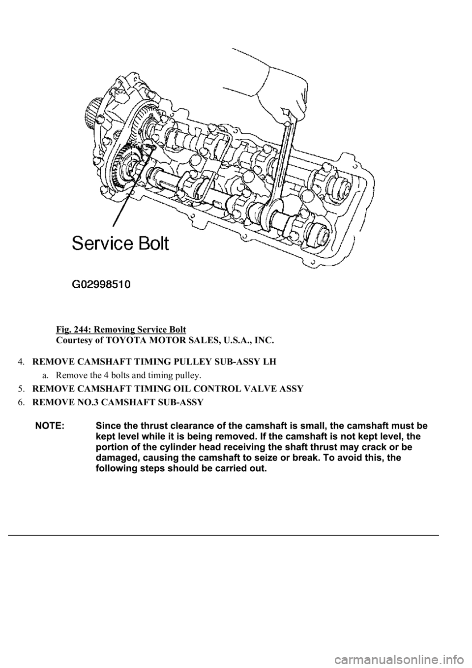
Fig. 244: Removing Service Bolt
Courtesy of TOYOTA MOTOR SALES, U.S.A., INC.
4.REMOVE CAMSHAFT TIMING PULLEY SUB-ASSY LH
a. Remove the 4 bolts and timing pulley.
5.REMOVE CAMSHAFT TIMING OIL CONTROL VALVE ASSY
6.REMOVE NO.3 CAMSHAFT SUB-ASSY
Page 3554 of 4500
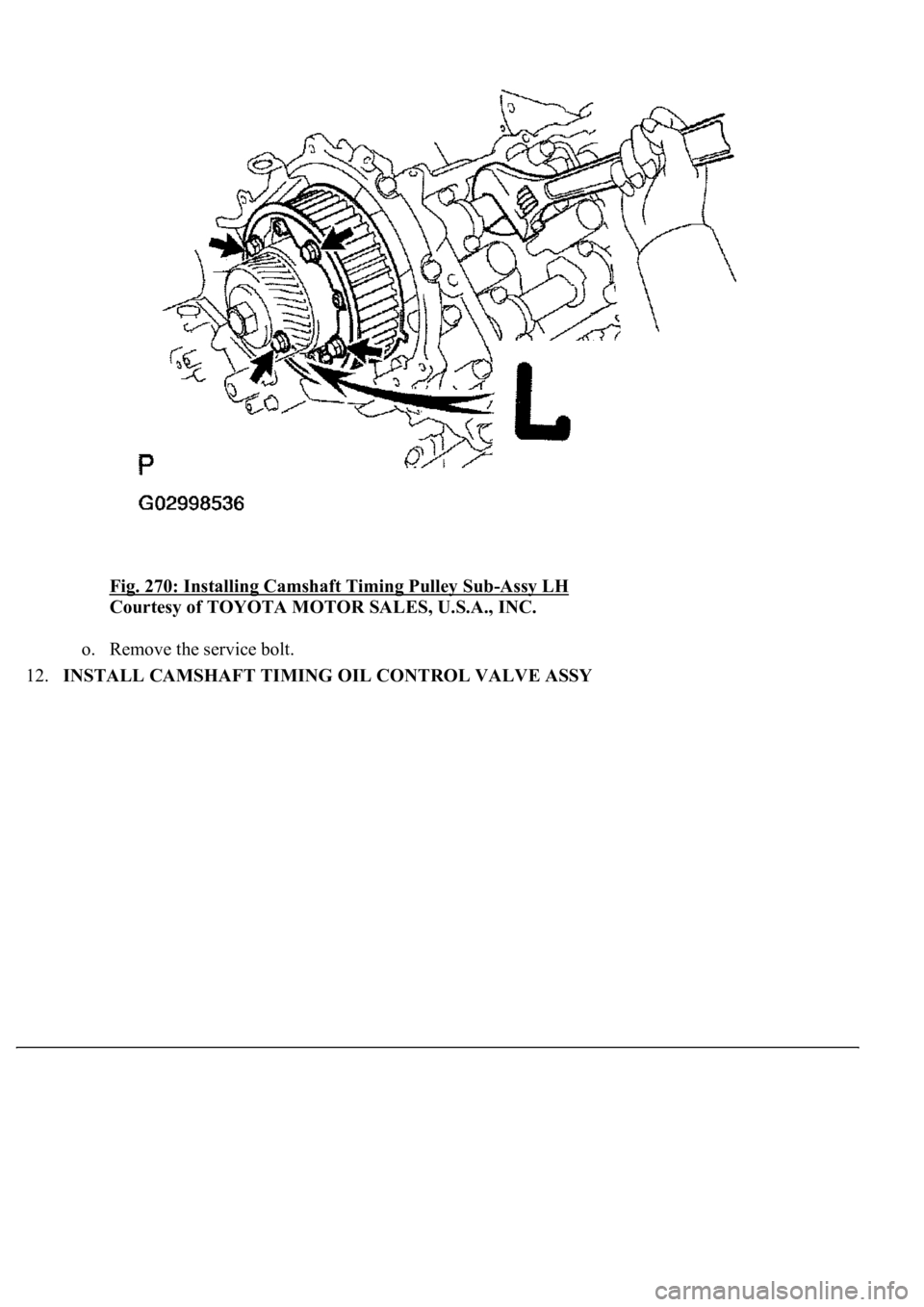
Fig. 270: Installing Camshaft Timing Pulley Sub-Assy LH
Courtesy of TOYOTA MOTOR SALES, U.S.A., INC.
o. Remove the service bolt.
12.INSTALL CAMSHAFT TIMING OIL CONTROL VALVE ASSY
Page 3556 of 4500
1.WORK FOR PREVENTING GASOLINE FROM SPILLING OUT (See PRECAUTION )
2.REMOVE CAMSHAFT (See REPLACEMENT
)
3.REMOVE THROTTLE BODY ASSY (See REPLACEMENT
)
4.REMOVE V-BANK COVER BRACKET NO.1
5.REMOVE V-BANK COVER BRACKET NO.2
6.REMOVE V-BANK COVER BRACKET NO.3
7.REMOVE V-VANK COVER BRACKET NO.4
8.REMOVE VACUUM SWITCHING VALVE ASSY
9.DISCONNECT FUEL PIPE SUB-ASSY NO.2 (See REPLACEMENT
)
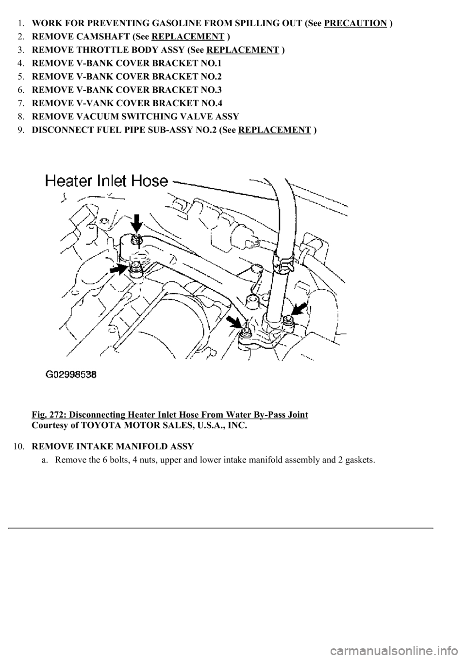
<0029004c004a001100030015001a0015001d00030027004c00560046005200510051004800460057004c0051004a0003002b004800440057004800550003002c0051004f004800570003002b005200560048000300290055005200500003003a0044005700
48005500030025005c[
-Pass Joint
Courtesy of TOYOTA MOTOR SALES, U.S.A., INC.
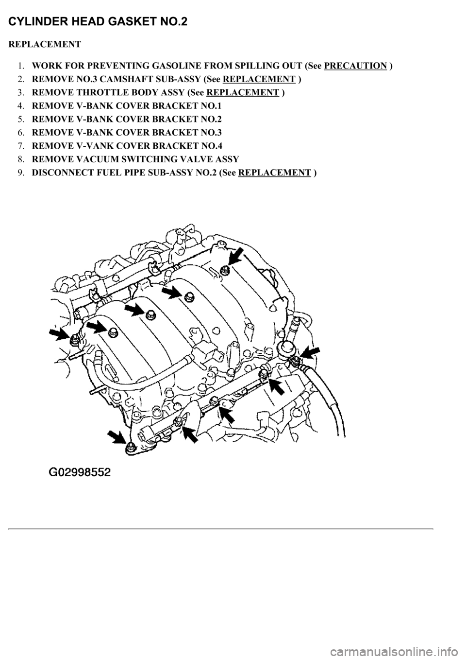
10.REMOVE INTAKE MANIFOLD ASSY
a. Remove the 6 bolts, 4 nuts, upper and lower intake manifold assembl
y and 2 gaskets.
Page 3569 of 4500
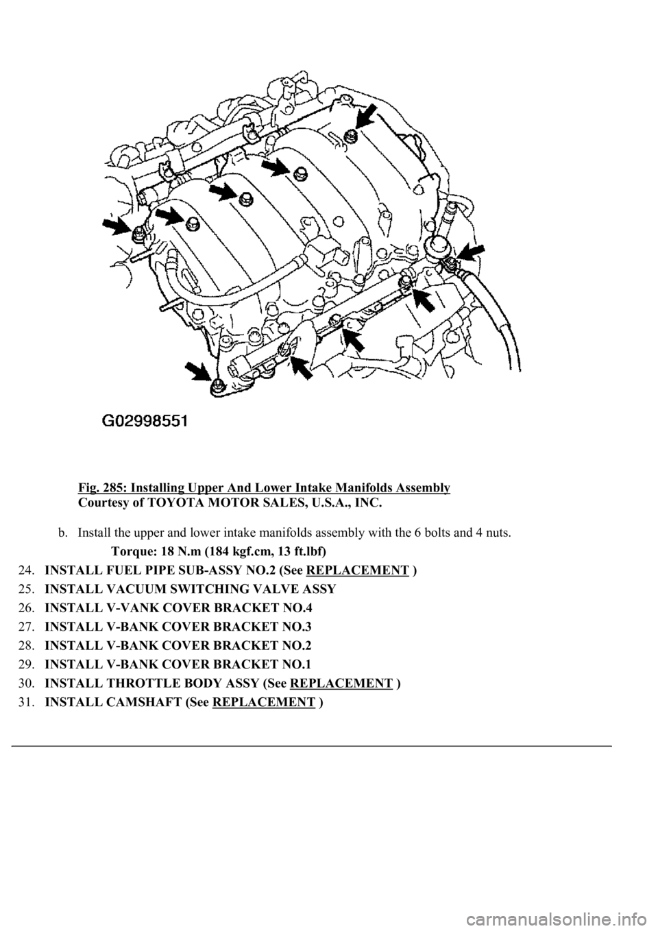
Fig. 285: Installing Upper And Lower Intake Manifolds Assembly
Courtesy of TOYOTA MOTOR SALES, U.S.A., INC.
b. Install the upper and lower intake manifolds assembly with the 6 bolts and 4 nuts.
Torque: 18 N.m (184 kgf.cm, 13 ft.lbf)
24.INSTALL FUEL PIPE SUB-ASSY NO.2 (See REPLACEMENT
)
25.INSTALL VACUUM SWITCHING VALVE ASSY
26.INSTALL V-VANK COVER BRACKET NO.4
27.INSTALL V-BANK COVER BRACKET NO.3
28.INSTALL V-BANK COVER BRACKET NO.2
29.INSTALL V-BANK COVER BRACKET NO.1
30.INSTALL THROTTLE BODY ASSY (See REPLACEMENT
)
31.INSTALL CAMSHAFT (See REPLACEMENT
)
Page 3570 of 4500
REPLACEMENT
1.WORK FOR PREVENTING GASOLINE FROM SPILLING OUT (See PRECAUTION
)
2.REMOVE NO.3 CAMSHAFT SUB-ASSY (See REPLACEMENT
)
3.REMOVE THROTTLE BODY ASSY (See REPLACEMENT
)
4.REMOVE V-BANK COVER BRACKET NO.1
5.REMOVE V-BANK COVER BRACKET NO.2
6.REMOVE V-BANK COVER BRACKET NO.3
7.REMOVE V-VANK COVER BRACKET NO.4
8.REMOVE VACUUM SWITCHING VALVE ASSY
9.DISCONNECT FUEL PIPE SUB-ASSY NO.2 (See REPLACEMENT
)
Page 3584 of 4500
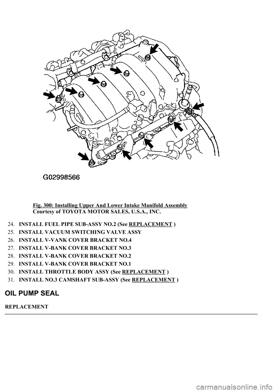
Fig. 300: Installing Upper And Lower Intake Manifold Assembly
Courtesy of TOYOTA MOTOR SALES, U.S.A., INC.
24.INSTALL FUEL PIPE SUB-ASSY NO.2 (See REPLACEMENT
)
25.INSTALL VACUUM SWITCHING VALVE ASSY
26.INSTALL V-VANK COVER BRACKET NO.4
27.INSTALL V-BANK COVER BRACKET NO.3
28.INSTALL V-BANK COVER BRACKET NO.2
29.INSTALL V-BANK COVER BRACKET NO.1
30.INSTALL THROTTLE BODY ASSY (See REPLACEMENT
)
31.INSTALL NO.3 CAMSHAFT SUB-ASSY (See REPLACEMENT
)
REPLACEMENT
Page 3596 of 4500
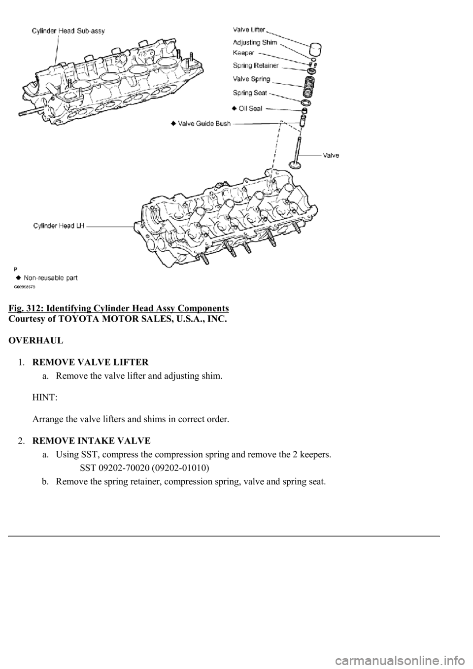
Fig. 312: Identifying Cylinder Head Assy Components
Courtesy of TOYOTA MOTOR SALES, U.S.A., INC.
OVERHAUL
1.REMOVE VALVE LIFTER
a. Remove the valve lifter and adjusting shim.
HINT:
Arrange the valve lifters and shims in correct order.
2.REMOVE INTAKE VALVE
a. Using SST, compress the compression spring and remove the 2 keepers.
SST 09202-70020 (09202-01010)
b. Remove the spring retainer, compression spring, valve and spring seat.
Page 4129 of 4500
REPLACEMENT
1.WORK FOR PREVENTING GASOLINE FROM SPILLING OUT (See PRECAUTION
)
2.DISCONNECT BATTERY NEGATIVE TERMINAL
3.REMOVE V-BANK COVER
a. Remove the 2 nuts and V-bank cover.
4.REMOVE AIR CLEANER INLET NO.1
5.REMOVE INTAKE AIR CONNECTOR PIPE
a. Disconnect the air hose and ventilation hose No. 1.
b. Loosen the hose clamp.
c. Remove the bolt and intake air connector pipe.
6.REMOVE V-BANK COVER BRACKET NO.1
7.REMOVE V-BANK COVER BRACKET NO.2
8.REMOVE V-BANK COVER BRACKET NO.3
9.REMOVE V-VANK COVER BRACKET NO.4
10.REMOVE VACUUM SWITCHING VALVE ASSY
11.DISCONNECT ENGINE WIRE
Page 4133 of 4500
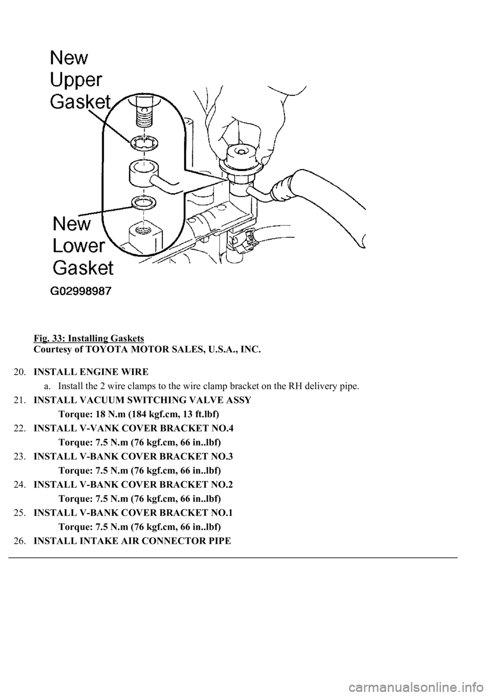
Fig. 33: Installing Gaskets
Courtesy of TOYOTA MOTOR SALES, U.S.A., INC.
20.INSTALL ENGINE WIRE
a. Install the 2 wire clamps to the wire clamp bracket on the RH delivery pipe.
21.INSTALL VACUUM SWITCHING VALVE ASSY
Torque: 18 N.m (184 kgf.cm, 13 ft.lbf)
22.INSTALL V-VANK COVER BRACKET NO.4
Torque: 7.5 N.m (76 kgf.cm, 66 in..lbf)
23.INSTALL V-BANK COVER BRACKET NO.3
Torque: 7.5 N.m (76 kgf.cm, 66 in..lbf)
24.INSTALL V-BANK COVER BRACKET NO.2
Torque: 7.5 N.m (76 kgf.cm, 66 in..lbf)
25.INSTALL V-BANK COVER BRACKET NO.1
Torque: 7.5 N.m (76 kgf.cm, 66 in..lbf)
26.INSTALL INTAKE AIR CONNECTOR PIPE