check engine LEXUS LS430 2003 Factory Manual PDF
[x] Cancel search | Manufacturer: LEXUS, Model Year: 2003, Model line: LS430, Model: LEXUS LS430 2003Pages: 4500, PDF Size: 87.45 MB
Page 1865 of 4500
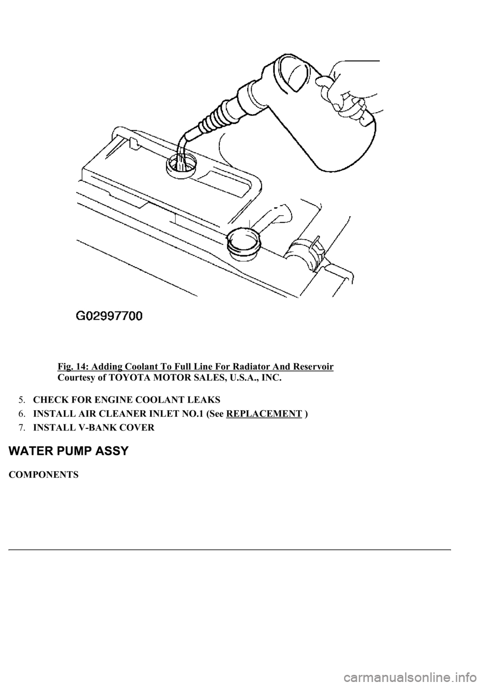
Fig. 14: Adding Coolant To Full Line For Radiator And Reservoir
Courtesy of TOYOTA MOTOR SALES, U.S.A., INC.
5.CHECK FOR ENGINE COOLANT LEAKS
6.INSTALL AIR CLEANER INLET NO.1 (See REPLACEMENT
)
7.INSTALL V-BANK COVER
COMPONENTS
Page 1872 of 4500
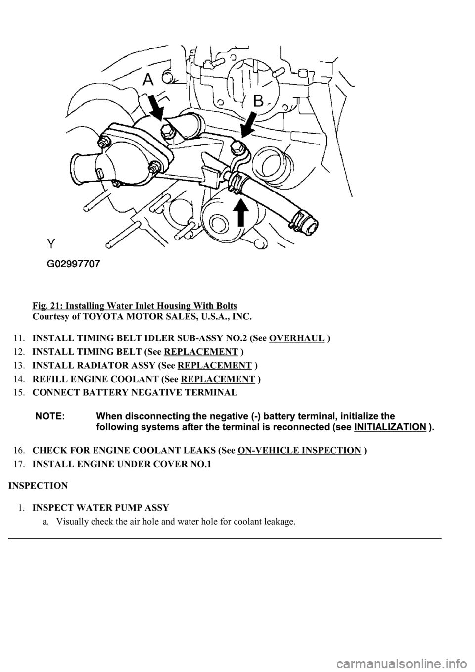
Fig. 21: Installing Water Inlet Housing With Bolts
Courtesy of TOYOTA MOTOR SALES, U.S.A., INC.
11.INSTALL TIMING BELT IDLER SUB-ASSY NO.2 (See OVERHAUL
)
12.INSTALL TIMING BELT (See REPLACEMENT
)
13.INSTALL RADIATOR ASSY (See REPLACEMENT
)
14.REFILL ENGINE COOLANT (See REPLACEMENT
)
15.CONNECT BATTERY NEGATIVE TERMINAL
16.CHECK FOR ENGINE COOLANT LEAKS (See ON
-VEHICLE INSPECTION )
17.INSTALL ENGINE UNDER COVER NO.1
INSPECTION
1.INSPECT WATER PUMP ASSY
a. Visuall
y<00030046004b00480046004e00030057004b004800030044004c00550003004b0052004f004800030044005100470003005a00440057004800550003004b0052004f004800030049005200550003004600520052004f0044005100570003004f0048004400
4e0044[ge.
Page 1873 of 4500
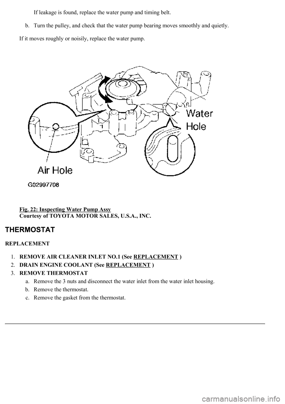
If leakage is found, replace the water pump and timing belt.
b. Turn the pulley, and check that the water pump bearing moves smoothly and quietly.
If it moves roughly or noisily, replace the water pump.
Fig. 22: Inspecting Water Pump Assy
Courtesy of TOYOTA MOTOR SALES, U.S.A., INC.
REPLACEMENT
1.REMOVE AIR CLEANER INLET NO.1 (See REPLACEMENT
)
2.DRAIN ENGINE COOLANT (See REPLACEMENT
)
3.REMOVE THERMOSTAT
a. Remove the 3 nuts and disconnect the water inlet from the water inlet housing.
b. Remove the thermostat.
c. Remove the
gasket from the thermostat.
Page 1876 of 4500
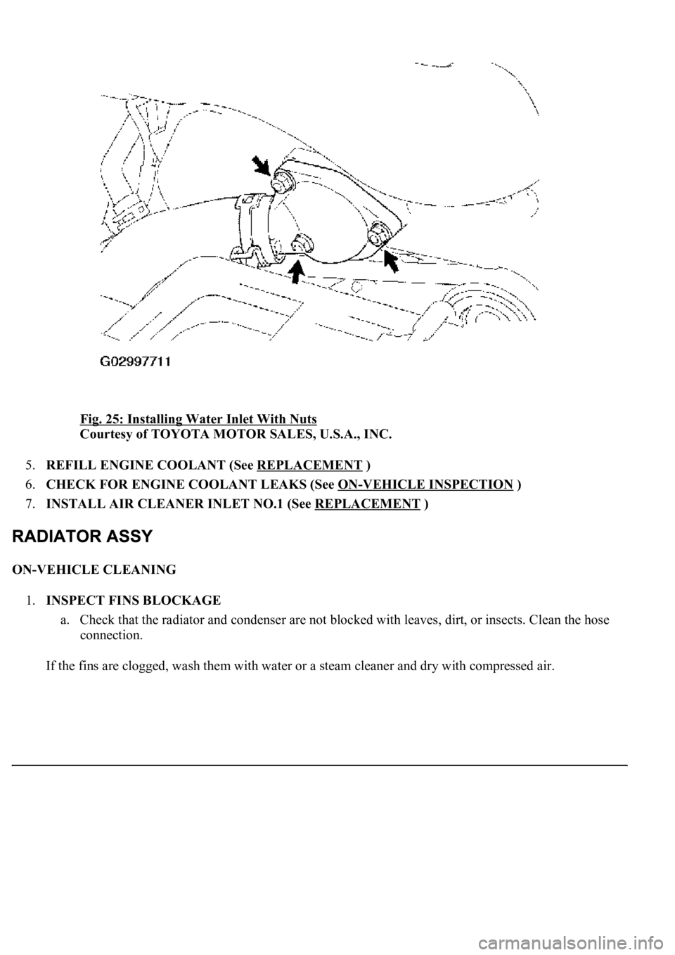
Fig. 25: Installing Water Inlet With Nuts
Courtesy of TOYOTA MOTOR SALES, U.S.A., INC.
5.REFILL ENGINE COOLANT (See REPLACEMENT
)
6.CHECK FOR ENGINE COOLANT LEAKS (See ON
-VEHICLE INSPECTION )
7.INSTALL AIR CLEANER INLET NO.1 (See REPLACEMENT
)
ON-VEHICLE CLEANING
1.INSPECT FINS BLOCKAGE
a. Check that the radiator and condenser are not blocked with leaves, dirt, or insects. Clean the hose
connection.
If the fins are clo
gged, wash them with water or a steam cleaner and dry with compressed air.
Page 1881 of 4500
13.REMOVE FAN ASSY
a. Disconnect the radiator reservoir hose from the radiator.
b. Remove the 6 bolts and fan.
14.INSTALL FAN ASSY
a. Install the fan with the 6 bolts.
Torque: 5.0 Nm (51 kgfcm, 44 in.lbf)
b. Connect the radiator reservoir hose to the radiator.
15.INSTALL RADIATOR AND FAN ASSEMBLY
a. Install the 2 radiator lower supports to the radiator.
b. Attach the 2 radiator lower supports on the radiator to the body bracket.
c. Install the radiator and fan assembly with the 2 radiator upper supports and 2 nuts.
Torque: 13.5 N m (138 kgf cm, 10 ft lbf)
d. Connect the cooling fan ECU connector.
16.INSTALL AIR CLEANER ASSY
17.INSTALL AIR CLEANER INLET NO.1
18.REFILL ENGINE COOLANT (See REPLACEMENT
)
19.CHECK FOR ENGINE COOLANT LEAKS
20.INSTALL ENGINE UNDER COVER NO.1
21.CONNECT BATTERY NEGATIVE TERMINAL
OVERHAUL
1.REMOVE PACKING
2.REMOVE RADIATOR CAP SUB-ASSY
3.REMOVE DRAIN PLUG
a. Remove the drain plug.
b. Remove the O-ring.
4.ASSEMBLE SST
SST 09230-01010
a. Install the claw to the overhaul handle, inserting it in the hole in part A as shown in the illustration
b. While gripping the handle, adjust the stopper bolt so that dimension B is as shown in the
illustration.
Page 1948 of 4500
3. With the brake pedal depressed, push the cruise control main switch to RES/ACC 3 times within 3
seconds. Check that the VSC buzzer sounds at this time.
REPLACEMENT
1.SEPARATE BATTERY NEGATIVE TERMINAL
2.REMOVE ENGINE UNDER COVER NO. 1 (See REPLACEMENT
)
3.REMOVE FRONT WHEEL OPENING EXTENSION PAD LH (See REPLACEMENT
)
4.REMOVE FRONT FENDER LINER LH (See REPLACEMENT
)
5.REMOVE FRONT WHEEL OPENING EXTENSION PAD RH (See REPLACEMENT
)
6.REMOVE FRONT FENDER LINER RH (See REPLACEMENT
)
7.REMOVE FRONT BUMPER COVER (See step 5 in REPLACEMENT
)
8.REMOVE FRONT BUMPER REINFORCEMENT SUB-ASSY (See step 9 in REPLACEMENT
)
9.REMOVE LASER SENSOR
a. Disconnect the connector and remove the laser sensor.
Page 2000 of 4500
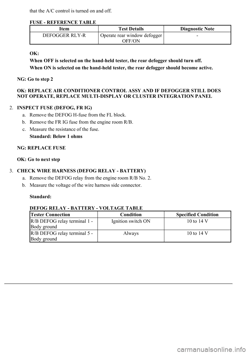
that the A/C control is turned on and off.
FUSE - REFERENCE TABLE
OK:
When OFF is selected on the hand-held tester, the rear defogger should turn off.
When ON is selected on the hand-held tester, the rear defogger should become active.
NG: Go to step 2
OK: REPLACE AIR CONDITIONER CONTROL ASSY AND IF DEFOGGER STILL DOES
NOT OPERATE, REPLACE MULTI-DISPLAY OR CLUSTER INTEGRATION PANEL
2.INSPECT FUSE (DEFOG, FR IG)
a. Remove the DEFOG H-fuse from the FL block.
b. Remove the FR IG fuse from the engine room R/B.
c. Measure the resistance of the fuse.
Standard: Below 1 ohms
NG: REPLACE FUSE
OK: Go to next step
3.CHECK WIRE HARNESS (DEFOG RELAY - BATTERY)
a. Remove the DEFOG relay from the engine room R/B No. 2.
b. Measure the voltage of the wire harness side connector.
Standard:
DEFOG RELAY - BATTERY - VOLTAGE TABLE
ItemTest DetailsDiagnostic Note
DEFOGGER RLY-ROperate rear window defogger
OFF/ON-
Tester ConnectionConditionSpecified Condition
R/B DEFOG relay terminal 1 -
Body groundIgnition switch ON10 to 14 V
R/B DEFOG relay terminal 5 -
Body groundAlways10 to 14 V
Page 2001 of 4500
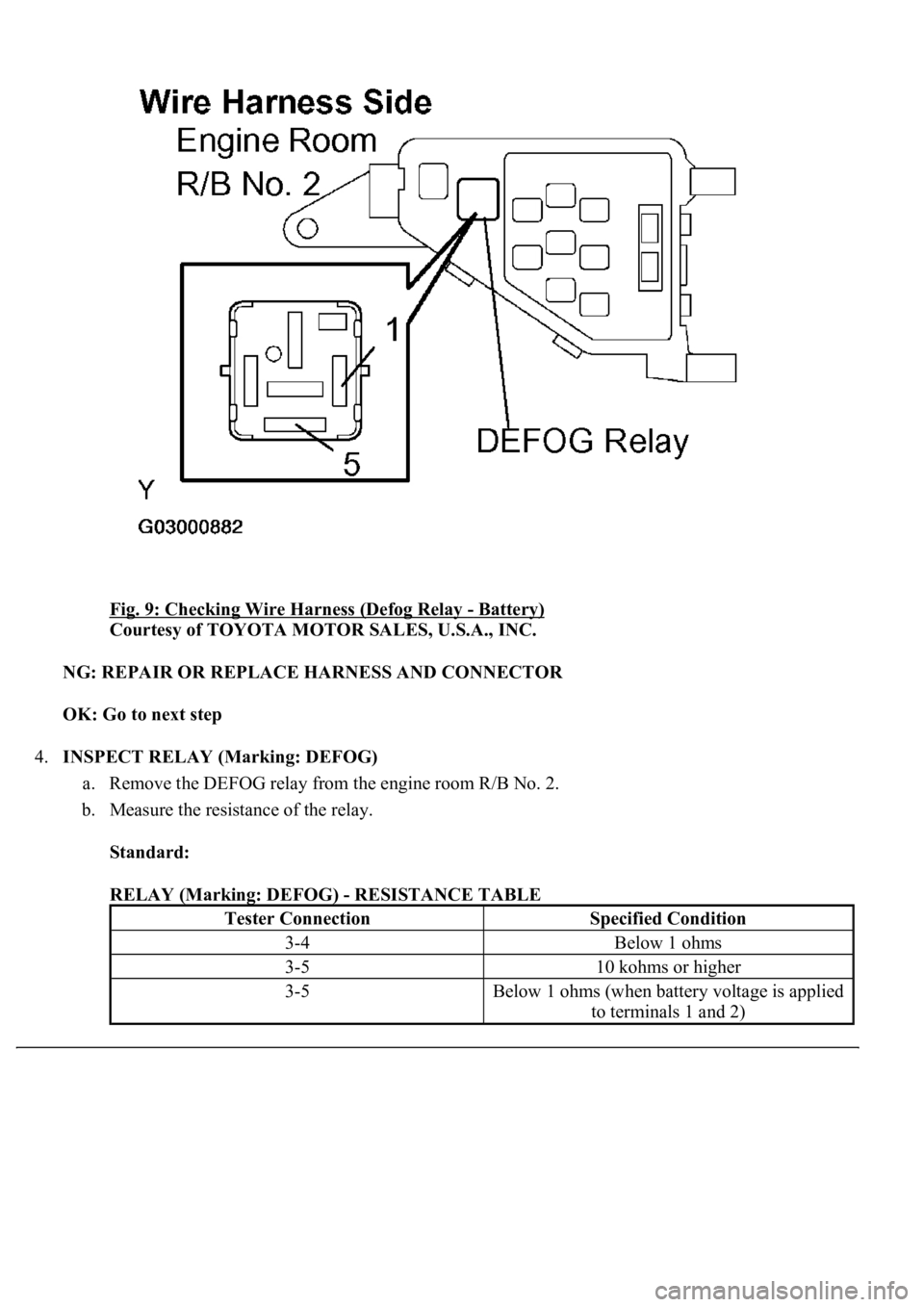
Fig. 9: Checking Wire Harness (Defog Relay - Battery)
Courtesy of TOYOTA MOTOR SALES, U.S.A., INC.
NG: REPAIR OR REPLACE HARNESS AND CONNECTOR
OK: Go to next step
4.INSPECT RELAY (Marking: DEFOG)
a. Remove the DEFOG relay from the engine room R/B No. 2.
b. Measure the resistance of the relay.
Standard:
RELAY (Marking: DEFOG) - RESISTANCE TABLE
Tester ConnectionSpecified Condition
3-4Below 1 ohms
3-510 kohms or higher
3-5Below 1 ohms (when battery voltage is applied
to terminals 1 and 2)
Page 2002 of 4500
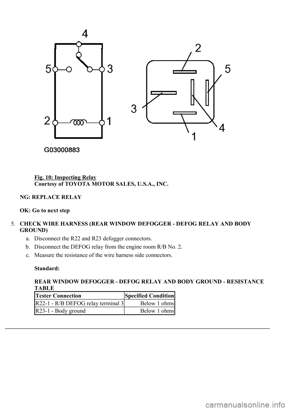
Fig. 10: Inspecting Relay
Courtesy of TOYOTA MOTOR SALES, U.S.A., INC.
NG: REPLACE RELAY
OK: Go to next step
5.CHECK WIRE HARNESS (REAR WINDOW DEFOGGER - DEFOG RELAY AND BODY
GROUND)
a. Disconnect the R22 and R23 defogger connectors.
b. Disconnect the DEFOG relay from the engine room R/B No. 2.
c. Measure the resistance of the wire harness side connectors.
Standard:
REAR WINDOW DEFOGGER - DEFOG RELAY AND BODY GROUND - RESISTANCE
TABLE
Tester ConnectionSpecified Condition
R22-1 - R/B DEFOG relay terminal 3Below 1 ohms
R23-1 - Body groundBelow 1 ohms
Page 2004 of 4500
OK: Go to next step
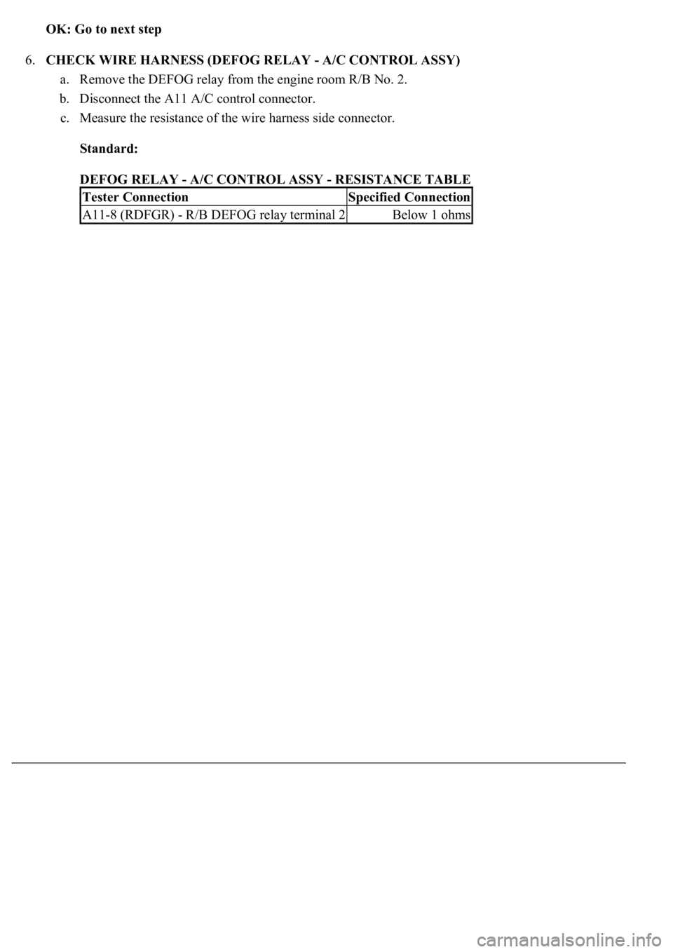
6.CHECK WIRE HARNESS (DEFOG RELAY - A/C CONTROL ASSY)
a. Remove the DEFOG relay from the engine room R/B No. 2.
b. Disconnect the A11 A/C control connector.
c. Measure the resistance of the wire harness side connector.
Standard:
DEFOG RELAY - A/C CONTROL ASSY - RESISTANCE TABLE
Tester ConnectionSpecified Connection
A11-8 (RDFGR) - R/B DEFOG relay terminal 2Below 1 ohms