LEXUS LS430 2003 Factory Manual PDF
LS430 2003
LEXUS
LEXUS
https://www.carmanualsonline.info/img/36/57050/w960_57050-0.png
LEXUS LS430 2003 Factory Manual PDF
Page 836 of 4500
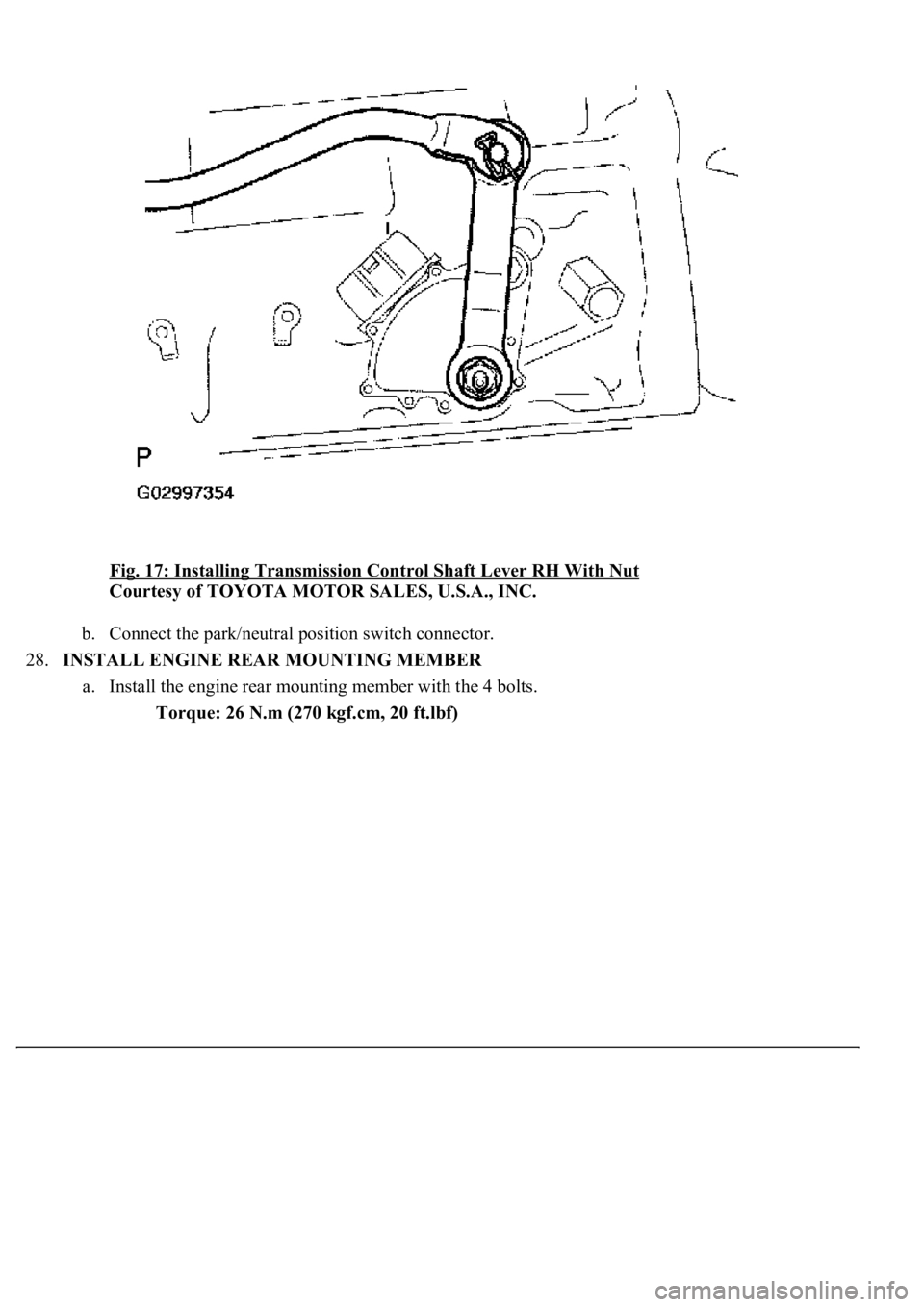
Fig. 17: Installing Transmission Control Shaft Lever RH With Nut
Courtesy of TOYOTA MOTOR SALES, U.S.A., INC.
b. Connect the park/neutral position switch connector.
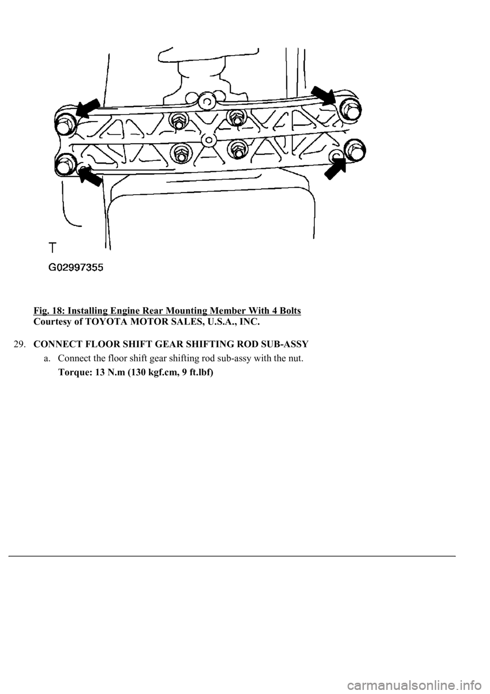
28.INSTALL ENGINE REAR MOUNTING MEMBER
a. Install the engine rear mounting member with the 4 bolts.
Torque: 26 N.m (270 kgf.cm, 20 ft.lbf)
Page 837 of 4500
Fig. 18: Installing Engine Rear Mounting Member With 4 Bolts
Courtesy of TOYOTA MOTOR SALES, U.S.A., INC.
29.CONNECT FLOOR SHIFT GEAR SHIFTING ROD SUB-ASSY
a. Connect the floor shift gear shifting rod sub-assy with the nut.
Torque: 13 N.m (130 kgf.cm, 9 ft.lbf)
Page 838 of 4500

<0029004c004a001100030014001c001d00030026005200510051004800460057004c0051004a00030029004f00520052005500030036004b004c004900570003002a00480044005500030036004b004c00490057004c0051004a0003003500520047000300
3600580045[-Assy With Nut
Courtesy of TOYOTA MOTOR SALES, U.S.A., INC.
30.CONNECT BATTERY NEGATIVE TERMINAL
31.ADJUST SHIFT LEVER POSITION (SEE ADJUSTMENT
)
32.INSPECT SHIFT LEVER POSITION (SEE ADJUSTMENT
33.INSPECT PARK/NEUTRAL POSITION SWITCH ASSY (SEE ADJUSTMENT
)
34.INSTALL PROPELLER W/CENTER BEARING SHAFT ASSY (SEE OVERHAUL
)
35.INSTALL EXHAUST PIPE ASSY (SEE REPLACEMENT
)
36.PERFORM INITIALIZATION (SEE INITIALIZATION
)
ADJUSTMENT
1.INSPECT PARK/NEUTRAL POSITION SWITCH ASSY
a. Apply the parking brake and turn the ignition switch to the ON position.
b. Depress the brake pedal and check that the engine starts when the shift lever is set in the N or P
position, but does not start in other positions.
c. Check that the back-up light comes on and the reverse warning buzzer sounds when the shift lever
is set in the R position, but do not function in other positions.
Page 844 of 4500
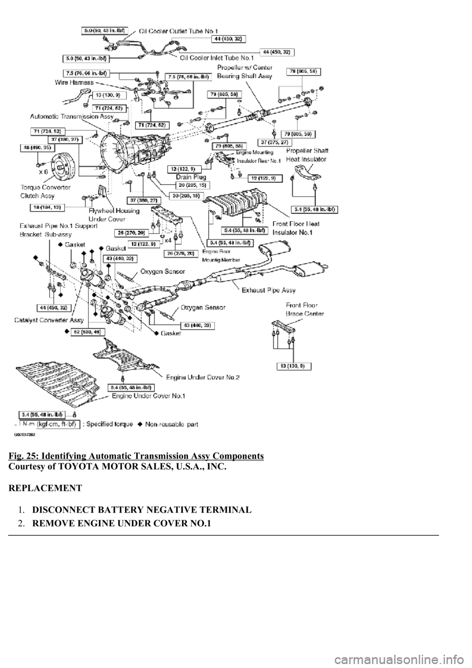
Fig. 25: Identifying Automatic Transmission Assy Components
Courtesy of TOYOTA MOTOR SALES, U.S.A., INC.
REPLACEMENT
1.DISCONNECT BATTERY NEGATIVE TERMINAL
2.REMOVE ENGINE UNDER COVER NO.1
Page 845 of 4500
3.REMOVE ENGINE UNDER COVER NO.2
4.REMOVE INSTRUMENT PANEL UNDER COVER SUB-ASSY NO.2 (SEE REPLACEMENT
)
5.REMOVE INSTRUMENT PANEL GARNISH SUB-ASSY LH (SEE REPLACEMENT
)
6.REMOVE INSTRUMENT PANEL FINISH PANEL (SEE REPLACEMENT
)
7.REMOVE INSTRUMENT PANEL UNDER COVER SUB-ASSY NO.1 (SEE REPLACEMENT
)
8.REMOVE SWITCH BRACE HOLE COVER (SEE REPLACEMENT
)
9.REMOVE INSTRUMENT PANEL SAFETY PAD SUB-ASSY NO.1 (SEE REPLACEMENT
)
10.REMOVE INSTRUMENT PANEL CUP HOLDER ASSY (SEE REPLACEMENT
)
11.REMOVE CONSOLE UPPER REAR PANEL SUB-ASSY (SEE REPLACEMENT
)
12.REMOVE CONSOLE BOX CARPET (SEE REPLACEMENT
)
13.REMOVE REAR CONSOLE ARMREST ASSY (SEE REPLACEMENT
)
14.REMOVE INSTRUMENT PANEL FINISH PANEL LOWER CENTER (SEE REPLACEMENT
)
15.REMOVE INSTRUMENT CLUSTER FINISH PANEL SUB-ASSY CENTER (SEE
REPLACEMENT
)
16.REMOVE CONSOLE PANEL SUB-ASSY UPPER (SEE REPLACEMENT
)
17.REMOVE CONSOLE BOX (SEE REPLACEMENT
)
18.SEPARATE OXYGEN SENSOR (SEE REPLACEMENT
)
a. Separate the 2 heated oxygen sensors.
19.REMOVE FRONT FLOOR BRACE CENTER (SEE REPLACEMENT
)
20.REMOVE EXHAUST PIPE ASSY (SEE REPLACEMENT
)
21.REMOVE FRONT FLOOR HEAT INSULATOR NO.1 (SEE OVERHAUL
)
22.REMOVE PROPELLER W/CENTER BEARING SHAFT ASSY (SEE OVERHAUL
)
SST 09922-10010
23.DRAIN AUTOMATIC TRANSMISSION FLUID
a. Remove the drain plug, gasket and drain the ATF.
b.Install a new gasket and the drain plug.
Torque: 20 N.m (205 kgf.cm, 15 ft.lbf)
24.REMOVE EXHAUST PIPE NO.1 SUPPORT BRACKET SUB-ASSY
a. Remove the 2 bolts and exhaust pipe No.1 support bracket sub-ass
y.
Page 847 of 4500
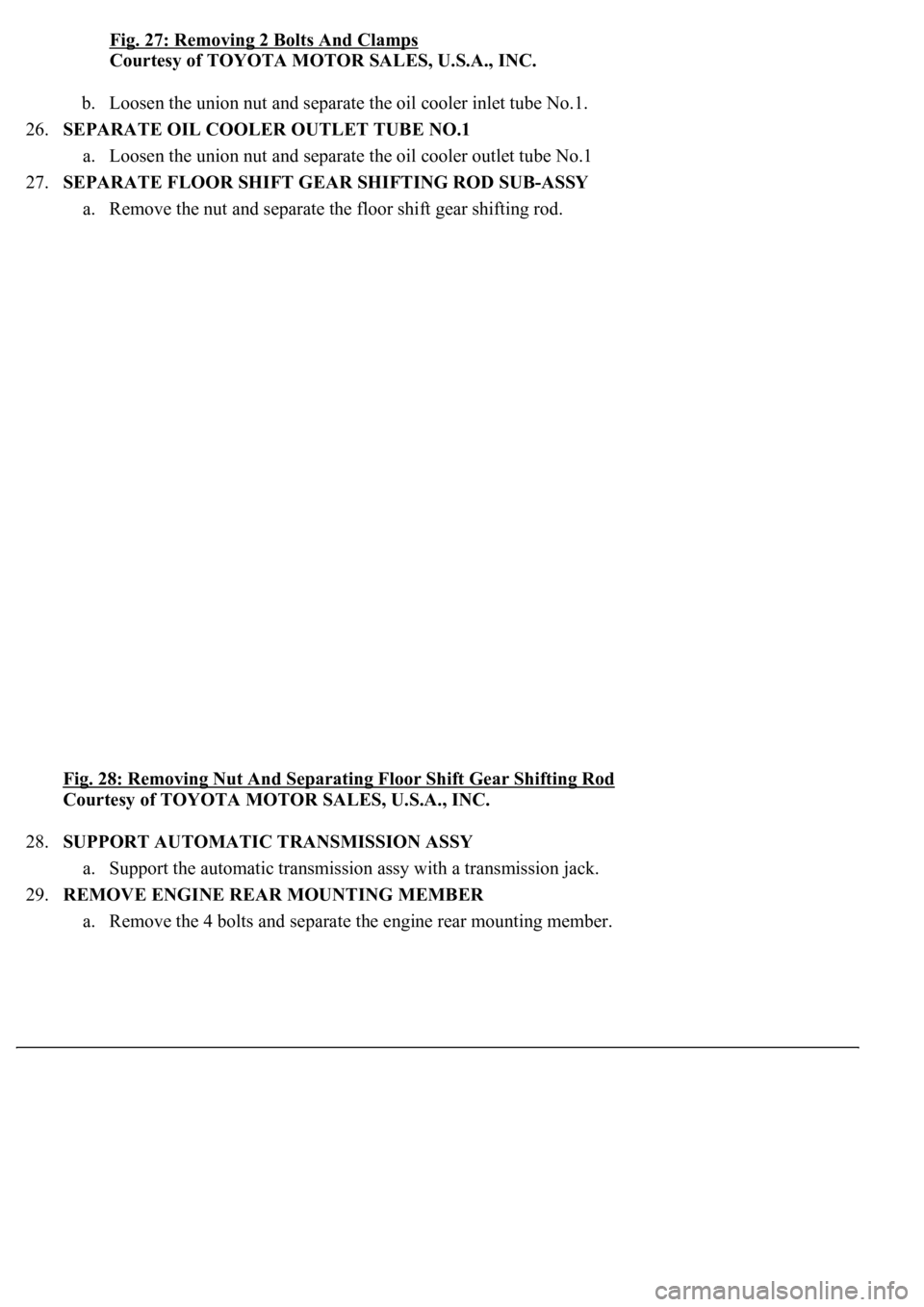
Fig. 27: Removing 2 Bolts And Clamps
Courtesy of TOYOTA MOTOR SALES, U.S.A., INC.
b. Loosen the union nut and separate the oil cooler inlet tube No.1.
26.SEPARATE OIL COOLER OUTLET TUBE NO.1
a. Loosen the union nut and separate the oil cooler outlet tube No.1
27.SEPARATE FLOOR SHIFT GEAR SHIFTING ROD SUB-ASSY
a. Remove the nut and separate the floor shift gear shifting rod.
Fig. 28: Removing Nut And Separating Floor Shift Gear Shifting Rod
Courtesy of TOYOTA MOTOR SALES, U.S.A., INC.
28.SUPPORT AUTOMATIC TRANSMISSION ASSY
a. Support the automatic transmission assy with a transmission jack.
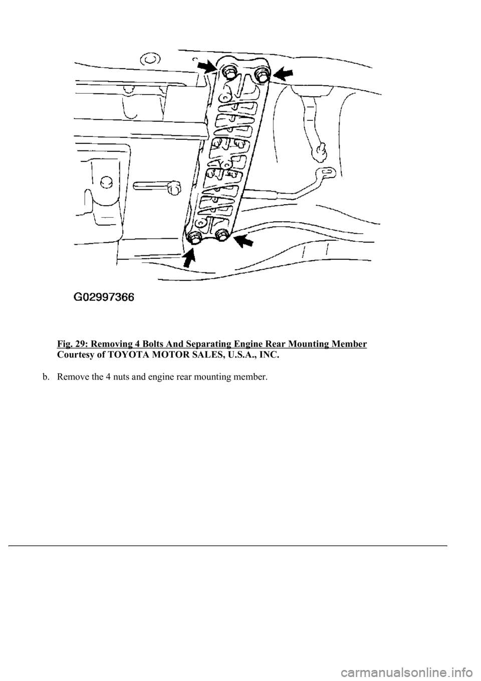
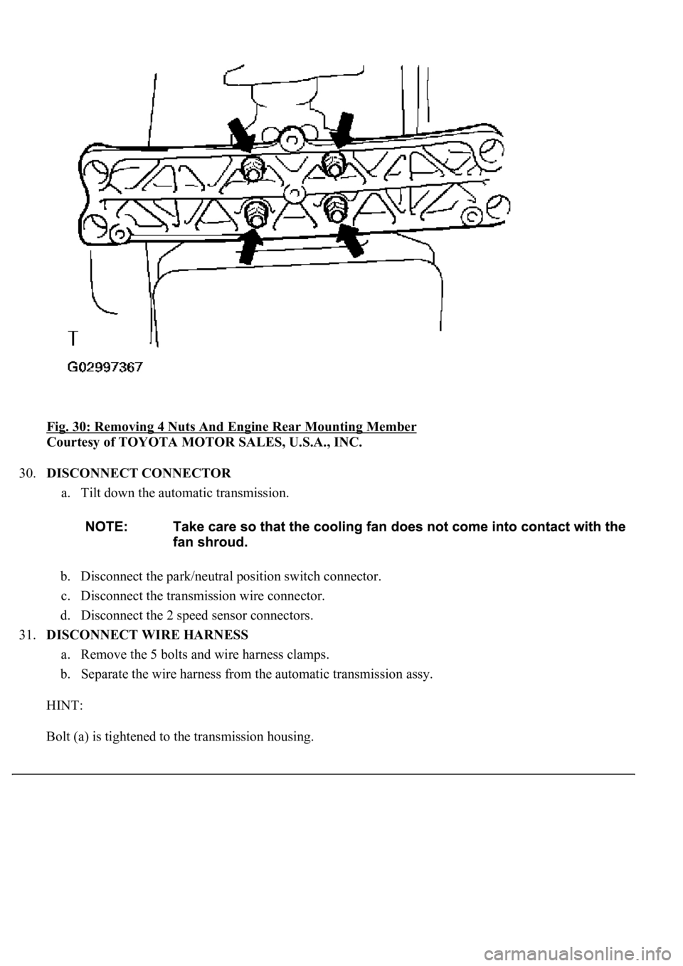
29.REMOVE ENGINE REAR MOUNTING MEMBER
a. Remove the 4 bolts and separate the engine rear mounting member.
Page 848 of 4500
Fig. 29: Removing 4 Bolts And Separating Engine Rear Mounting Member
Courtesy of TOYOTA MOTOR SALES, U.S.A., INC.
b. Remove the 4 nuts and engine rear mounting member.
Page 849 of 4500
Fig. 30: Removing 4 Nuts And Engine Rear Mounting Member
Courtesy of TOYOTA MOTOR SALES, U.S.A., INC.
30.DISCONNECT CONNECTOR
a. Tilt down the automatic transmission.
b. Disconnect the park/neutral position switch connector.
c. Disconnect the transmission wire connector.
d. Disconnect the 2 speed sensor connectors.
31.DISCONNECT WIRE HARNESS
a. Remove the 5 bolts and wire harness clamps.
b. Separate the wire harness from the automatic transmission assy.
HINT:
Bolt (a) is ti
ghtened to the transmission housing.
Page 852 of 4500
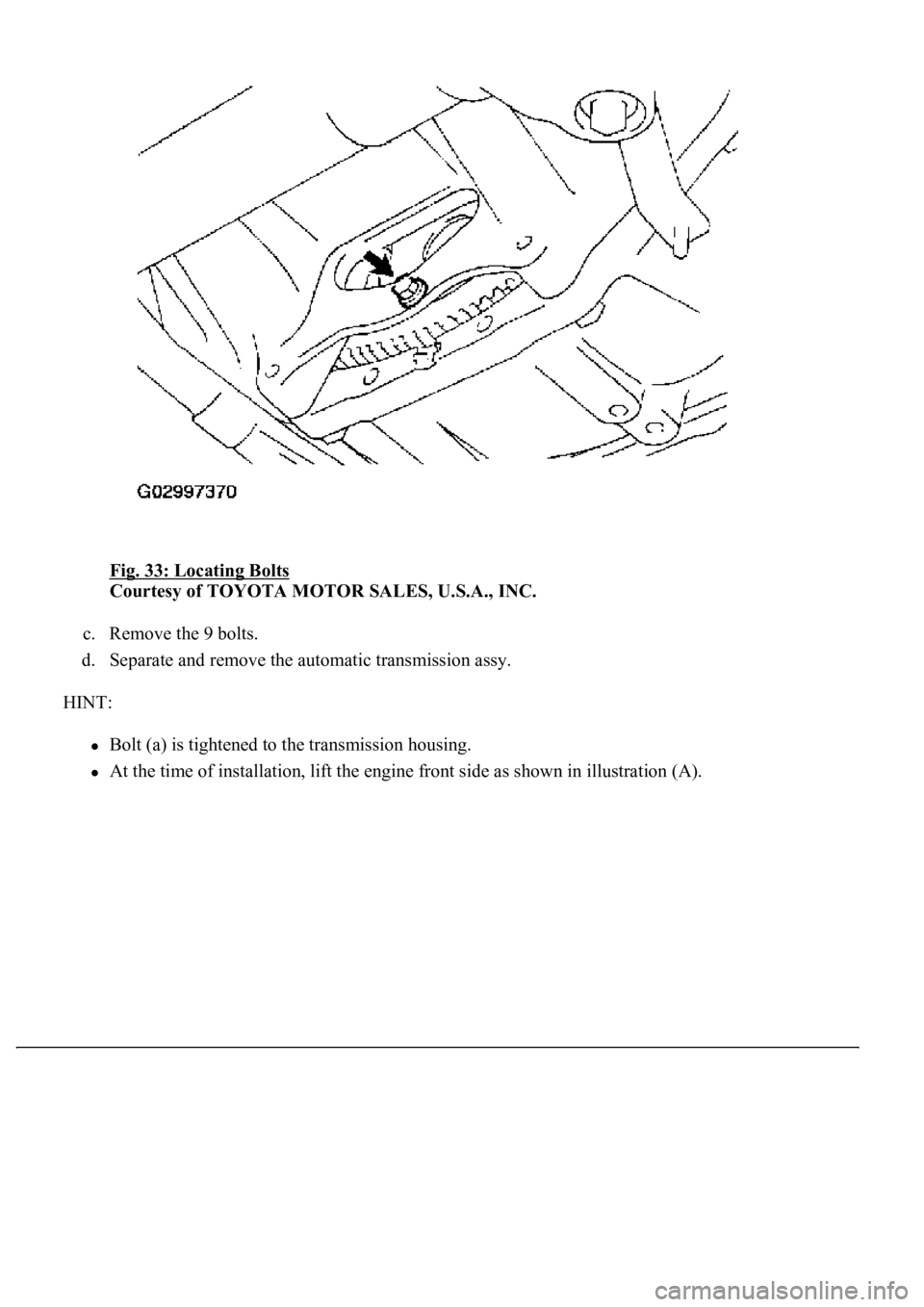
Fig. 33: Locating Bolts
Courtesy of TOYOTA MOTOR SALES, U.S.A., INC.
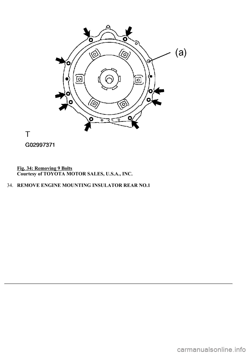
c. Remove the 9 bolts.
d. Separate and remove the automatic transmission assy.
HINT:
Bolt (a) is tightened to the transmission housing.
At the time of installation, lift the engine front side as shown in illustration (A).
Page 853 of 4500
Fig. 34: Removing 9 Bolts
Courtesy of TOYOTA MOTOR SALES, U.S.A., INC.
34.REMOVE ENGINE MOUNTING INSULATOR REAR NO.1
