engine LEXUS LS430 2003 Factory Owner's Guide
[x] Cancel search | Manufacturer: LEXUS, Model Year: 2003, Model line: LS430, Model: LEXUS LS430 2003Pages: 4500, PDF Size: 87.45 MB
Page 227 of 4500

ROOM TEMP
Room temperature sensor / min.: -
6.5°C (20.3°F) max.: 57.25°C
(126.95°F)
Actual room temperature is displayed-
AMBI TEMP
SENSAmbient temperature sensor /
min.: -23.3°C (-9.94°F) max.:
65.95°C (150.71°F)Actual ambient temperature is
displayed-
EVAP TEMP
Evaporator temperature sensor /
min.: -29.7°C (-21.46°F) max.:
59.55°C (139.19°F)Actual evaporator temperature is
displayed-
SOLAR SENS-DSolar sensor (Driver side) / min.:
0 max.: 255Increases as brightness increases-
SOLAR SENS-PSolar sensor (Passenger side) /
min.: 0 max.: 255decreases as brightness increases-
COOLANT
TEMPEngine coolant temperature /
min.: 1.3°C (34.34°F) max.:
90.55°C (194.99°F)Actual engine coolant temperature is
displayed while the engine is warmed
up
-
DUCT TEMP-D
Duct sensor (Driver side) / min.: -
12.7°C (9.14°F) max.: 76.55°C
(169.79°F)Actual duct temperature is displayed
(Driver side)-
DUST TEMP-P
Duct sensor (Passenger side) /
min.: -12.7°C (9.14°F) max.:
76.55°C (169.79°F)Actual duct temperature is displayed
(Passenger side)-
SET TEMP-DSet temperature (Driver side) /
min.: 0 max.: 255Actual set temperature is displayed
(Driver side)-
SET TEMP-PSet temperature (Passenger
side) /min.: 0 max.: 255Actual set temperature is displayed
(Passenger side)-
ESTIMATE
TEMP-DEstimated temperature (Driver
side) / min.: -358.4°C (-613.12°F)
max.: 358.4°C (677.12°F)Actual estimated temperature is
displayed (Driver side)-
ESTIMATE
TEMP-PEstimated temperature (Passenger
side) / min.: -358.4°C (-613.12°F)
max.: 358.4°C (677.12°F)Actual estimated temperature is
displayed (Passenger side)-
A/I DAMP POSAir inlet damper position / min.: -
14% max.: 113.5%RECIRCULATION: Approx. 0%
FRESH: Approx. 100%-
A/B DAMP POS-
DCool air bypass damper position
(Driver side) / min.: -14% max.:
113.5%OPEN: Approx. 0 % SHUT: Approx.
100%-
A/B DAMP POS-
PCool air bypass damper position
(Passenger side) / min.: -14%
max.: 113.5%OPEN: Approx. 0 % SHUT: Approx.
100%-
ItemMeasurement Item / Display
(Range)Normal ConditionDiagnostic
Note
A/I DAMP
TARGAir inlet damper target / min.: -
14% max.: 113.5%RECIRCULATION: Approx. 0%
FRESH: Approx. 100% HALF-
RECIRCULATION: 43 to 99.5 %
-
Page 229 of 4500

DATA LIST / ENGINE AND ECT / ALL:
DATA LIST / ENGINE AND ECT / ALL
2.ACTIVE TEST
HINT:
Performing the ACTIVE TEST
using the hand-held tester allows the relays, VSV, actuators and so on to
operate without parts removal. Performing the ACTIVE TEST
as the first STEP of troubleshooting is
one way to shorten labor time.
It is possible to display the DATA LIST on the hand-held tester during the ACTIVE TEST.
a. Connect the hand-held tester to the DLC3.
b. Turn the ignition switch to the ON position.
c. From the display on tester, perform the "ACTIVE TEST
".
ACTIVE TEST / AIR CONDITIONER:
ACTIVE TEST / AIR CONDITIONER
FOOT AIR
LEAKFoot air leak / ON, OFFCustomized value will be displayed-
DESTINATION
Destination / DOMEST, USA,
EUROPE, AUSTRAL,
MIDEAST, NO INFO
Changes with destinations-
REAR SOLAR
SENSRear solar sensor / min.: 0 max.:
255Changes depending on brightness-
NOX GAS SENSEmission gas Nox sensor / min.: 0
max.: 255Increases as the gas amount increases-
ItemMeasurement Item / Display
(Range)Normal ConditionDiagnostic
Note
REG PRESS
SENSRegulator pressure sensor / min.:
0 max.: 255Actual regulator pressure is displayed-
FILTER FLOW
VOLFilter flow volume / min.: 0 max.:
65535Actual filter flow volume is displayed-
REG CTRL
CURRNTRegulator control current / min.: 0
A max.: 255 A--
HUMIDITY
SENSHumidity sensor / min.: 0% max.:
100%Actual room humidity is displayed-
#CODESNumber of Trouble Codes / min.:
0 max.: 255Number of DTCs will be displayed-
ItemMeasurement Item/Display (Range)Normal ConditionDiagnostic Note
A/C SIGA/C signal/ ON or OFFA/C ON: ON-
Page 299 of 4500
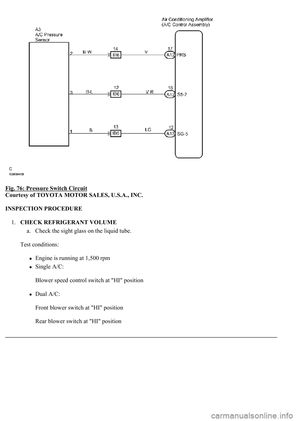
Fig. 76: Pressure Switch Circuit
Courtesy of TOYOTA MOTOR SALES, U.S.A., INC.
INSPECTION PROCEDURE
1.CHECK REFRIGERANT VOLUME
a. Check the sight glass on the liquid tube.
Test conditions:
Engine is running at 1,500 rpm
Single A/C:
Blower speed control switch at "HI" position
Dual A/C:
Front blower switch at "HI" position
Rear blower switch at "HI" position
Page 352 of 4500
Courtesy of TOYOTA MOTOR SALES, U.S.A., INC.
INSPECTION PROCEDURE
1.INSPECT AIR CONDITIONING AMPLIFIER (SOL+ - SOL-)
a. Remove the A/C amplifier with connectors still connected.
b. Turn the ignition switch to the ON position.
c. Measure the voltage according to the value (s) in the table below.
Standard:
AIR CONDITIONING AMPLIFIER (SOL+ - SOL-) VOLTAGE
HINT:
As the temperature increases, the voltage decreases.
Result:
AIR CONDITIONING AMPLIFIER (SOL+ - SOL-) TEST RESULT
Tester connectionConditionSpecified condition
A11-6 (SOL+) - A11-7 (SOL-)Start the engine Auto switch: ONBelow 1.0 V
ANG
BOK (Checking from the PROBLEM SYMPTOMS TABLE)
COK (Checking from the DTC)
Page 364 of 4500
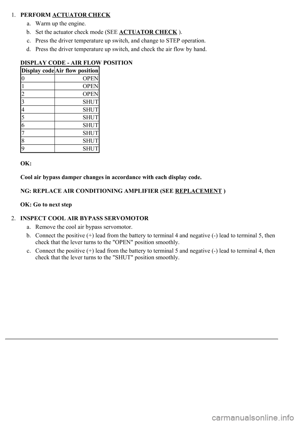
1.PERFORM ACTUATOR CHECK
a. Warm up the engine.
b. Set the actuator check mode (SEE ACTUATOR CHECK
).
c. Press the driver temperature up switch, and change to STEP operation.
d. Press the driver temperature up switch, and check the air flow by hand.
DISPLAY CODE - AIR FLOW POSITION
OK:
Cool air bypass damper changes in accordance with each display code.
NG: REPLACE AIR CONDITIONING AMPLIFIER (SEE REPLACEMENT
)
OK: Go to next step
2.INSPECT COOL AIR BYPASS SERVOMOTOR
a. Remove the cool air bypass servomotor.
b. Connect the positive (+) lead from the battery to terminal 4 and negative (-) lead to terminal 5, then
check that the lever turns to the "OPEN" position smoothly.
c. Connect the positive (+) lead from the battery to terminal 5 and negative (-) lead to terminal 4, then
check that the lever turns to the "SHUT" position smoothl
y.
Display codeAir flow position
0OPEN
1OPEN
2OPEN
3SHUT
4SHUT
5SHUT
6SHUT
7SHUT
8SHUT
9SHUT
Page 369 of 4500

Fig. 129: Cool Air Bypass Damper Control Servomotor Circuit (Passenger Side)
Courtesy of TOYOTA MOTOR SALES, U.S.A., INC.
INSPECTION PROCEDURE
1.PERFORM ACTUATOR CHECK
a. Warm up the engine.
b. Set the actuator check mode (SEE ACTUATOR CHECK
).
c. Press the driver temperature up switch, and change to STEP operation.
d. Press the driver temperature up switch, and check the air flow by hand.
Display code Air flow position
DISPLAY CODE AIR FLOW POSITION
OK:
Cool air bypass damper changes in accordance with each display code.
NG: REPLACE AIR CONDITIONING AMPLIFIER (SEE REPLACEMENT
)
OK: Go to next step
2.INSPECT COOL AIR BYPASS SERVOMOTOR
a. Remove the cool air bypass servomotor.
b. Connect the positive (+) lead from the battery to terminal 4 and negative (-) lead to terminal 5, then
check that the lever turns to the "OPEN" position smoothly.
c. Connect the positive (+) lead from the battery to terminal 5 and negative (-) lead to terminal 4, then
check that the lever turns to the "SHUT" position smoothly.
Display codeAir flow lever position
0OPEN
1OPEN
2OPEN
3SHUT
4SHUT
5SHUT
6SHUT
7SHUT
8SHUT
9SHUT
Page 374 of 4500
INSPECTION PROCEDURE
1.PERFORM ACTUATOR CHECK
a. Warm up the engine.
b. Set the actuator check mode (SEE ACTUATOR CHECK
).
c. Press the driver temperature up switch, and change to STEP operation.
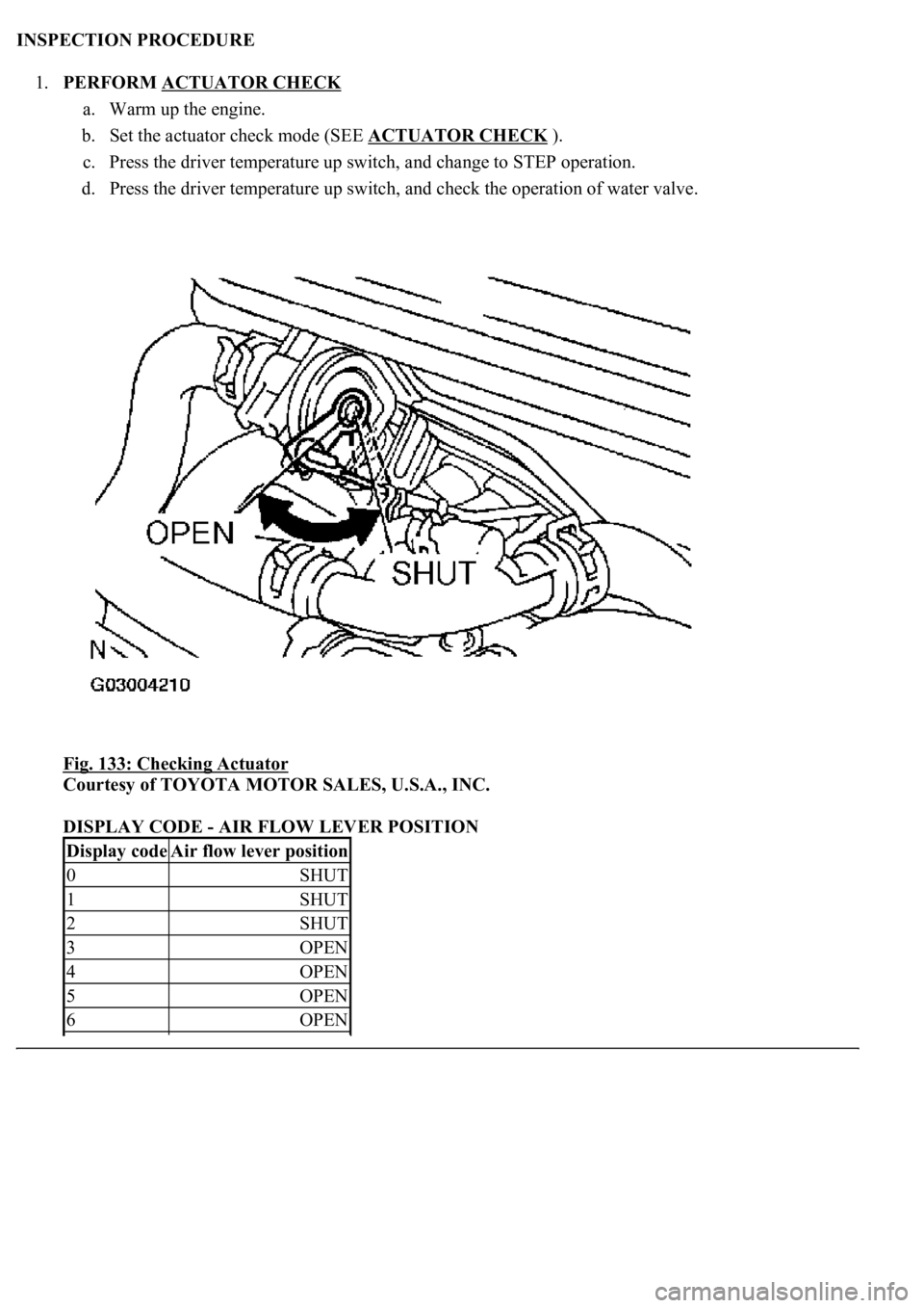
d. Press the driver temperature up switch, and check the operation of water valve.
Fig. 133: Checking Actuator
Courtesy of TOYOTA MOTOR SALES, U.S.A., INC.
DISPLAY CODE - AIR FLOW LEVER POSITION
Display codeAir flow lever position
0SHUT
1SHUT
2SHUT
3OPEN
4OPEN
5OPEN
6OPEN
Page 379 of 4500

Fig. 136: Air Vent Mode Damper Control Servomotor Circuit
Courtesy of TOYOTA MOTOR SALES, U.S.A., INC.
INSPECTION PROCEDURE
1.PERFORM ACTUATOR CHECK
a. Warm up the engine.
b. Set the actuator check mode (see ACTUATOR CHECK).
Page 403 of 4500
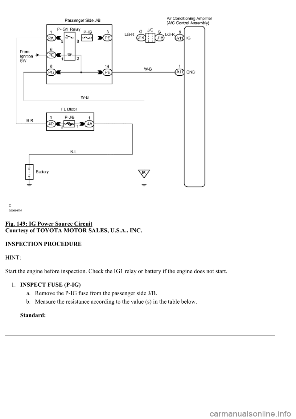
Fig. 149: IG Power Source Circuit
Courtesy of TOYOTA MOTOR SALES, U.S.A., INC.
INSPECTION PROCEDURE
HINT:
Start the engine before inspection. Check the IG1 relay or battery if the engine does not start.
1.INSPECT FUSE (P-IG)
a. Remove the P-IG fuse from the passenger side J/B.
b. Measure the resistance according to the value (s) in the table below.
Standard:
Page 425 of 4500
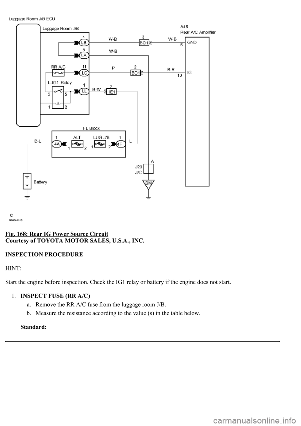
Fig. 168: Rear IG Power Source Circuit
Courtesy of TOYOTA MOTOR SALES, U.S.A., INC.
INSPECTION PROCEDURE
HINT:
Start the engine before inspection. Check the IG1 relay or battery if the engine does not start.
1.INSPECT FUSE (RR A/C)
a. Remove the RR A/C fuse from the luggage room J/B.
b. Measure the resistance according to the value (s) in the table below.
Standard: