sensor LEXUS LS430 2003 Factory Manual PDF
[x] Cancel search | Manufacturer: LEXUS, Model Year: 2003, Model line: LS430, Model: LEXUS LS430 2003Pages: 4500, PDF Size: 87.45 MB
Page 195 of 4500

Result:
DTC OUTPUT DESCRIPTION
B: REPAIR CIRCUIT INDICATED BY OUTPUT CODE (SEE DIAGNOSTIC TROUBLE CODE
CHART )
A: REPLACE ABS & TRACTION ACTUATOR ASSY (SEE REPLACEMENT
)
CIRCUIT DESCRIPTION
In the sensor check mode, a malfunction of the speed sensor that cannot be detected when the vehicle is stopped
is detected while driving.
Transition to the sensor check mode can be performed by connecting terminals TS and CG of the DLC3 and
turning the ignition switch from off to the ON position.
WIRING DIAGRAM
DTC is not outputA
DTC is outputB
Page 210 of 4500

Fig. 6: Air Conditioning System Diagram (2 Of 2)
Courtesy of TOYOTA MOTOR SALES, U.S.A., INC.
1.GENERAL
a. The air conditioning system has the following features:
In compliance with the temperature set at the temperature control switch, the neural network
control calculates the outlet temperature based on the input signals from various sensors. In
addition, corrections in accordance with the signals from the evaporative temperature sensor
and the water temperature sensor are added to control the outlet air temperature.
Controls the front and rear blower motors in accordance with the airflow volume that has
been calculated by the neural network control based on the input signals from various
sensors.
Automatically switches the outlets in accordance with the outlet mode ratio that has been
calculated by the neural network control based on the input signals from various sensors.
Automatically controls the air inlet control damper in accordance with the airflow volume
that has been calculated by the neural network control.
Turns the compressor on/off and controls the discharge capacity based on the signals from
various sensors.
Based on the signals from the ambient temperature sensor, this control calculates the outside
temperature, which is then corrected in the air conditioner ECU, and shown in the multi-
information display in the combination meter.
Switched the rear defogger and outside rear view mirror heaters on for 15 minutes when the
rear defogger switch is switched on. Switched them off if the switch is pressed while they are
operating.
Controls the orientation and the angle of the front center register based on the input signals
from various sensors and on the outlet mode.
Determines whether the clean air filter (for the front A/C) is clogged by monitoring the air
inlets, and airflow volume.
The A/C amplifier automatically controls the air inlets based on the signals from the smog
ventilation sensor.
Improves the air quality by linking the air inlet control damper and the blower motor (for the
rear A/C and air purifier), based on the signals from the exhaust gas sensor and the smoke
sensor.
Checks the sensors in accordance with operation of the air conditioner switches.
2.MODEL POSITION AND DAMPER OPERATION
Page 214 of 4500

The hand-held tester can be used in steps 3, 6, 7 and 11.
1.VEHICLE BROUGHT TO WORK SHOP
2.(SEE CUSTOMER PROBLEM ANALYSIS CHECK
)
a. Confirm problem symptoms.
3.CHECK AND CLEAR THE DTCS (SEE DTC CHECK/CLEAR
)
4.PROBLEM SYMPTOM CONFIRMATION
SYMPTOM OCCURS (GO TO STEP 6)
SYMPTOM DOES NOT OCCUR (GO TO STEP 5)
5.SYMPTOM SIMULATION (SEE HOW TO PROCEED WITH TROUBLESHOOTING
)
6.CHECK BODY MULTIPLEX COMMUNICATION SYSTEM (SEE HOW TO PROCEED WITH
TROUBLESHOOTING )
a. Check for the DTC output.
MULTIPLEX DTC OUTPUTS (PROCEED TO "MULTIPLEX COMMUNICATION SYSTEM
")
NO MULTIPLEX DTC (GO TO STEP 7)
7.CHECK CAN COMMUNICATION SYSTEM (SEE HOW TO PROCEED WITH
TROUBLESHOOTING )
a. Check for the DTC output.
CAN DTC OUTPUTS (PROCEED TO "CAN COMMUNICATION SYSTEM
")
NO CAN DTC (GO TO STEP 8)
8.DTC CHECK (OTHER THAN MULTIPLEX DTC) (SEE DTC CHECK/CLEAR
)
MALFUNCTION CODE (GO TO STEP 9)
NORMAL CODE (GO TO STEP 10)
9.(SEE DIAGNOSTIC TROUBLE CODE CHART
)
GO TO STEP 12
10.(SEE PROBLEM SYMPTOMS TABLE
)
11.(SEE ACTUATOR CHECK
)
12.CIRCUIT INSPECTION (SEE DTC B1411 ROOM TEMPERATURE SENSOR CIRCUIT
to
INTELLIGENT SWING REGISTER CIRCUIT
)
13.IDENTIFYING OF PROBLEMS
Page 226 of 4500

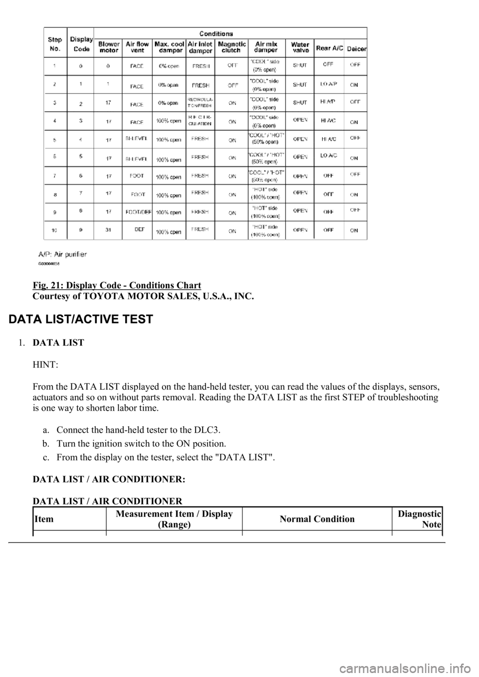
Fig. 21: Display Code - Conditions Chart
Courtesy of TOYOTA MOTOR SALES, U.S.A., INC.
1.DATA LIST
HINT:
From the DATA LIST displayed on the hand-held tester, you can read the values of the displays, sensors,
actuators and so on without parts removal. Reading the DATA LIST as the first STEP of troubleshooting
is one way to shorten labor time.
a. Connect the hand-held tester to the DLC3.
b. Turn the ignition switch to the ON position.
c. From the display on the tester, select the "DATA LIST".
DATA LIST / AIR CONDITIONER:
DATA LIST / AIR CONDITIONER
ItemMeasurement Item / Display
(Range)Normal ConditionDiagnostic
Note
Page 227 of 4500

ROOM TEMP
Room temperature sensor / min.: -
6.5°C (20.3°F) max.: 57.25°C
(126.95°F)
Actual room temperature is displayed-
AMBI TEMP
SENSAmbient temperature sensor /
min.: -23.3°C (-9.94°F) max.:
65.95°C (150.71°F)Actual ambient temperature is
displayed-
EVAP TEMP
Evaporator temperature sensor /
min.: -29.7°C (-21.46°F) max.:
59.55°C (139.19°F)Actual evaporator temperature is
displayed-
SOLAR SENS-DSolar sensor (Driver side) / min.:
0 max.: 255Increases as brightness increases-
SOLAR SENS-PSolar sensor (Passenger side) /
min.: 0 max.: 255decreases as brightness increases-
COOLANT
TEMPEngine coolant temperature /
min.: 1.3°C (34.34°F) max.:
90.55°C (194.99°F)Actual engine coolant temperature is
displayed while the engine is warmed
up
-
DUCT TEMP-D
Duct sensor (Driver side) / min.: -
12.7°C (9.14°F) max.: 76.55°C
(169.79°F)Actual duct temperature is displayed
(Driver side)-
DUST TEMP-P
Duct sensor (Passenger side) /
min.: -12.7°C (9.14°F) max.:
76.55°C (169.79°F)Actual duct temperature is displayed
(Passenger side)-
SET TEMP-DSet temperature (Driver side) /
min.: 0 max.: 255Actual set temperature is displayed
(Driver side)-
SET TEMP-PSet temperature (Passenger
side) /min.: 0 max.: 255Actual set temperature is displayed
(Passenger side)-
ESTIMATE
TEMP-DEstimated temperature (Driver
side) / min.: -358.4°C (-613.12°F)
max.: 358.4°C (677.12°F)Actual estimated temperature is
displayed (Driver side)-
ESTIMATE
TEMP-PEstimated temperature (Passenger
side) / min.: -358.4°C (-613.12°F)
max.: 358.4°C (677.12°F)Actual estimated temperature is
displayed (Passenger side)-
A/I DAMP POSAir inlet damper position / min.: -
14% max.: 113.5%RECIRCULATION: Approx. 0%
FRESH: Approx. 100%-
A/B DAMP POS-
DCool air bypass damper position
(Driver side) / min.: -14% max.:
113.5%OPEN: Approx. 0 % SHUT: Approx.
100%-
A/B DAMP POS-
PCool air bypass damper position
(Passenger side) / min.: -14%
max.: 113.5%OPEN: Approx. 0 % SHUT: Approx.
100%-
ItemMeasurement Item / Display
(Range)Normal ConditionDiagnostic
Note
A/I DAMP
TARGAir inlet damper target / min.: -
14% max.: 113.5%RECIRCULATION: Approx. 0%
FRESH: Approx. 100% HALF-
RECIRCULATION: 43 to 99.5 %
-
Page 228 of 4500

AIR MIX STEP-
DAir mix servomotor target STEP
(Driver side) / min.: 257 STEP
max.: 1571 STEPMAX COOL: Approx. 257 STEP
MAX HOT: Approx. 1,571 STEP-
AIR MIX STEP-
PAir mix servomotor target STEP
(Passenger side) / min.: 257 STEP
max.: 1571 STEPMAX COOL: Approx. 257 STEP
MAX HOT: Approx. 1,571 STEP-
AIR OUT STEP-
DAir outlet servomotor target STEP
(Driver side) / min.: 274 STEP
max.: 2060 STEPFACE: Approx. 274 STEP DEF:
Approx. 2,060 STEP-
AIR OUT STEP-
PAir outlet servomotor target STEP
(Passenger side) / min.: 274 STEP
max.: 2060 STEPFACE: Approx. 274 STEP DEF:
Approx. 2,060 STEP-
HAND FREE
TELHand free telephone / OFF, ON--
BLOWER
LEVELBlower motor speed level / min.:
0 level max.: 31 levelIncreases in the range between 0 and
31 as the speed increase-
AMBI TEMP
Adjusted ambient temperature /
min.: -30.8°C (-23.44°F) max.:
50.8°C (123.44°F)
--
LOW VOLT
COUNT+B abnormal low voltage / min.: 0
times max.: 255 times--
EMISS GAS
SENSEmission gas / min.: 0 V max.:
255 VIncreases as the gas amount increases-
SET TEMP
SHIFTShift set temperature / +2C, +1C,
NORMAL, -1C, -2CCustomized value will be displayed-
AIR INLET
MODEAir inlet mode / AUTO,
MANUALCustomized value will be displayed-
COMPRESSOR
MODECompressor mode / AUTO,
MANUALCustomized value will be displayed-
COMPRS/DEF
OPERCompressor/ DEF operation
mode /LINK, NORMALCustomized value will be displayed-
MOTOR
INITIALIZEMotor initialize after IG SW being
turned OFFCustomized value will be displayed-
EVAP CTRLEvaporator control /AUTO,
MANUALCustomized value will be displayed-
GAS SENS
SHIFT
Emission Gas Sensor Shift / MU
MORE, MORE, LI MORE,
NORMAL, LI LESS, LESS, MU
LESS
Customized value will be displayed-
AUTO MODESwing resister auto mode /
AUTO, MANUALCustomized value will be displayed-
BUTTON PRS
BUZButton press buzzer / ON, OFFCustomized value will be displayed-
FILTER SENSFilter sensor / LESS, NORMAL,
MORECustomized value will be displayed-
Page 229 of 4500

DATA LIST / ENGINE AND ECT / ALL:
DATA LIST / ENGINE AND ECT / ALL
2.ACTIVE TEST
HINT:
Performing the ACTIVE TEST
using the hand-held tester allows the relays, VSV, actuators and so on to
operate without parts removal. Performing the ACTIVE TEST
as the first STEP of troubleshooting is
one way to shorten labor time.
It is possible to display the DATA LIST on the hand-held tester during the ACTIVE TEST.
a. Connect the hand-held tester to the DLC3.
b. Turn the ignition switch to the ON position.
c. From the display on tester, perform the "ACTIVE TEST
".
ACTIVE TEST / AIR CONDITIONER:
ACTIVE TEST / AIR CONDITIONER
FOOT AIR
LEAKFoot air leak / ON, OFFCustomized value will be displayed-
DESTINATION
Destination / DOMEST, USA,
EUROPE, AUSTRAL,
MIDEAST, NO INFO
Changes with destinations-
REAR SOLAR
SENSRear solar sensor / min.: 0 max.:
255Changes depending on brightness-
NOX GAS SENSEmission gas Nox sensor / min.: 0
max.: 255Increases as the gas amount increases-
ItemMeasurement Item / Display
(Range)Normal ConditionDiagnostic
Note
REG PRESS
SENSRegulator pressure sensor / min.:
0 max.: 255Actual regulator pressure is displayed-
FILTER FLOW
VOLFilter flow volume / min.: 0 max.:
65535Actual filter flow volume is displayed-
REG CTRL
CURRNTRegulator control current / min.: 0
A max.: 255 A--
HUMIDITY
SENSHumidity sensor / min.: 0% max.:
100%Actual room humidity is displayed-
#CODESNumber of Trouble Codes / min.:
0 max.: 255Number of DTCs will be displayed-
ItemMeasurement Item/Display (Range)Normal ConditionDiagnostic Note
A/C SIGA/C signal/ ON or OFFA/C ON: ON-
Page 231 of 4500

IG - GND (A11-9
- A11-1)LG-R -
W-BPower source (IG)Ignition switch OFF.0 V
TSDr - GND
(A11-19 - A11-1)L - W-BSolar sensor signal (Driver
side)Ignition switch ON. Solar sensor
subjected to electric light.0.8 to 4.3 V
TSDr - GND
(A11-19 - A11-1)L - W-BSolar sensor signal (Driver
side)Ignition switch ON. Solar sensor
covered by a cloth.Below 0.8 V
TSPa - GND
(A11-20 - A11-1)G-R - W-
BSolar sensor signal
(Passenger side)Ignition switch ON. Solar sensor
subjected to electric light.0.8 to 4.3 V
TSPa - GND
(A11-20 - A11-1)G-R - W-
BSolar sensor signal
(Passenger side)Ignition switch ON. Solar sensor
covered by a cloth.Below 0.8 V
+B - GND (A11-
21 - A11-1)B-Y - W-
BPower source (Back-up)Always10 to 14 V
DGS - SG-1
(A11-29 - A13-8)B - YExhaust gas sensor signal
After 30 seconds from Ignition
switch ON and the sensor is
exposed to the exhaust gas.
1.0 to 4.5 V
DS1 - GND
(A12-1 - A11-1)V - W-BSwing grill STEP motor
signal
Ignition switch ON. Blower
motor: Operating Mode selector:
BI-LEVEL Intelligent swing
register: ON
Pulse
generation
Symbols
(Terminal No.)Wiring
colorTerminal DescriptionConditionSpecification
DS2 - GND
(A12-2 - A11-1)G - W-BSwing grill STEP motor
signal
Ignition switch ON. Blower
motor: Operating Mode selector:
BI-LEVEL Intelligent swing
register: ON
Pulse
generation
PS1 - GND (A12-
3 - A11-1)R-B - W-
BSwing grill STEP motor
signal
Ignition switch ON. Blower
motor: Operating Mode selector:
BI-LEVEL Intelligent swing
register: ON
Pulse
generation
PS2 - GND (A12-
4 - A11-1)B - W-BSwing grill STEP motor
signal
Ignition switch ON. Blower
motor: Operating Mode selector:
BI-LEVEL Intelligent swing
register: ON
Pulse
generation
PS3 - GND (A12-
5 - A11-1)P - W-BSwing grill STEP motor
signal
Ignition switch ON. Blower
motor: Operating Mode selector:
BI-LEVEL Intelligent swing
register: ON
Pulse
generation
PS4 - GND (A12-
6 - A11-1)Y-R - W-
BSwing grill STEP motor
signal
Ignition switch ON. Blower
motor: Operating Mode selector:
BI-LEVEL Intelligent swing
register: ON
Pulse
generation
DUAL - DrGND
(A12-7 - A12-11)O - LG-RDual temperature control
signalIgnition switch ON. Dual switch
ON.Below 1.0 V
DUAL - DrGND
(A12-7 - A12-11)O - LG-RDual temperature control
signalIgnition switch ON. Dual switch
OFF.10 to 14 V
Page 232 of 4500

DS3 - GND
(A12-8 - A11-1)B-R - W-
BSwing grill STEP motor
signal
Ignition switch ON. Blower
motor: Operating Mode selector:
BI-LEVEL Intelligent swing
register: ON
Pulse
generation
DS4 - GND
(A12-9 - A11-1)G-B - W-
BSwing grill STEP motor
signal
Ignition switch ON. Blower
motor: Operating Mode selector:
BI-LEVEL Intelligent swing
register: ON
Pulse
generation
DUIND+ -
DUIND - (A12-
10 - A12-13)G-R - B-
WDriver temperature and
passenger temperature
communication signalDriver temperature and passenger
temperature are different.5 to 14 V
DUIND+ -
DUIND- (A12-10
- A12-13)G-R - B-
WDriver temperature and
passenger temperature
communication signalDriver temperature and passenger
temperature are the same.Below 1.0 V
S5-2 - SG-5
(A12-15 - A13-
12)
V-R - LGPressure sensor operation
voltageIgnition switch ON.4.5 to 5.5 V
S5-4 - TSRr(2)
(A12-16 - A11-
30)
GR - W-LRear solar sensor signalIgnition switch ON. Rear solar
sensor subjected to electric light.0.8 to 4.3 V
S5-4 - TSRr(2)
(A12-16 - A11-
30)
GR - W-LRear solar sensor signalIgnition switch ON. Rear solar
sensor covered by a cloth.Below 1.0 V
PRS - SG-5
(A12-17 - A13-
12)
V - LGPressure sensor signalRefrigerant pressure 0 Mpa (0
kgf.cm, 0 psi).0.5V
PRS - SG-5
(A12-17 - A13-
12)
V - LGPressure sensor signalRefrigerant pressure 2.9 Mpa (30
kgf.cm, 427 psi).4.5 V
TAMOUT - GND
(1) (A12-18 -
A11-1)L - W-BVehicle speed signalIgnition switch ON.Pulse
generation
PaDN - PaGND
(A12-19 - A12-
12)R-W - Y-
RTemperature control
switch signal (Passenger
side)Push passenger temperature
switch OFF.10 to 14 V
PaDN - PaGND
(A12-19 - A12-
12)R-W - Y-
RTemperature control
switch signal (Passenger
side)Push passenger temperature
switch ON.Below 1.0 V
PaUP - PaGND
(A12-20 - A12-
12)
W - Y-R
Temperature control
switch signal (Passenger
side)Push passenger temperature
switch OFF.10 to 14 V
Symbols
(Terminal No.)Wiring
colorTerminal DescriptionConditionSpecification
PaUP - PaGND
(A12-20 - A12-W - Y-RTemperature control
switch signal (Passenger
Push passenger temperature Below 1.0 V
Page 233 of 4500

12)side)switch ON.
DrDN - DrGND
(A12-21 - A12-
11)P-L - LG-
RTemperature control
switch signal (Driver side)Push driver temperature switch
OFF.10 to 14 V
DrDN - DrGND
(A12-21 - A12-
11)P-L - LG-
RTemperature control
switch signal (Driver side)Push driver temperature switch
ON.Below 1.0 V
DrUP - DrGND
(A12-22 - A12-
11)V-W -
LG-RTemperature control
switch signal (Driver side)Push driver temperature switch
OFF.10 to 14 V
DrUP - DrGND
(A12-22 - A12-
11)V-W -
LG-RTemperature control
switch signal (Driver side)Push driver temperature switch
ON.Below 1.0 V
PS+B - GND
(A12-24 - A11-1)R-G - W-
BSwing grill STEP motor
operation voltageAlways10 to 14 V
TFACEPa - SG-4
(A13-14 - A13-
11)B-Y - Y-
GDuct sensor signal
(Passenger side)Ignition switch ON. Passenger
side duct sensor temperature 25 °
C (77 °F).
1.8 to 2.2 V
TFACEPa - SG-4
(A13-14 - A13-
11)B-Y - Y-
GDuct sensor signal
(Passenger side)Ignition switch ON. Passenger
side duct sensor temperature 50 °
C (122 °F).
0.8 to 1.2 V
TFACEDr - SG-3
(A13-15 - A13-
10)GR-R -
R-WDuct sensor signal (Driver
side)Ignition switch ON. Passenger
side duct sensor temperature 25 °
C (77 °F).
1.8 to 2.2 V
TFACEDr - SG-3
(A13-15 - A13-
10)GR-R -
R-WDuct sensor signal (Driver
side)Ignition switch ON. Passenger
side duct sensor temperature 50 °
C (122 °F).
0.8 to 1.2 V
TR - SG-2 (A13-
16 - A13-9)W-L - Y-
BRoom temperature sensor
signalIgnition switch ON. Room
temperature 25 °C (77°F).1.8 to 2.2 V
TR - SG-2 (A13-
16 - A13-9)W-L - Y-
BRoom temperature sensor
signalIgnition switch ON. Room
temperature 40 °C (104°F).0.8 to 1.2 V
NOX - Body
ground (A13-17 -
Body ground)L-B -
Body
ground
Exhaust gas sensor signal
After 120 seconds from Ignition
switch ON and the sensor is
exposed to the exhaust gas.
1.0 to 4.5 V
AMDr1 - GND
(A37-1 - A11-1)BR - W-B
Air mix servomotor
operation signal (Driver
side)During actuator check mode.
Change display code 0 to display
code 9.Pulse
generation
AMDr2 - GND
(A37-2 - A11-1)BR-B -
W-BAir mix servomotor
operation signal (Driver
side)During actuator check mode.
Change display code 0 to display
code 9.Pulse
generation
AMDr3 - GND
(A37-3 - A11-1)BR-W -
W-BAir mix servomotor
operation signal (Driver
side)During actuator check mode.
Change display code 0 to display
code 9.Pulse
generation
AMDr4 - GND
(A37-4 - A11-1)BR-Y -
W-BAir mix servomotor
operation signal (Driver During actuator check mode.
Change display code 0 to display Pulse
generation