wheel LEXUS LS430 2003 Factory Service Manual
[x] Cancel search | Manufacturer: LEXUS, Model Year: 2003, Model line: LS430, Model: LEXUS LS430 2003Pages: 4500, PDF Size: 87.45 MB
Page 968 of 4500
Fig. 5: Depressing Brake Pedal Several Times And Loosen Bleeder Plug
Courtesy of TOYOTA MOTOR SALES, U.S.A., INC.
c. When fluid stops coming out, tighten the bleeder plug, then release the brake pedal.
d. Repeat (b) and (c) until all the air in the fluid is completely bled out.
e. Tighten the bleeder plug completely.
Torque: 11 N.m (110 kgf.cm, 8 ft.lbf)
f. Repeat the above procedures for each wheel to bleed the air out of the brake line.
Page 972 of 4500
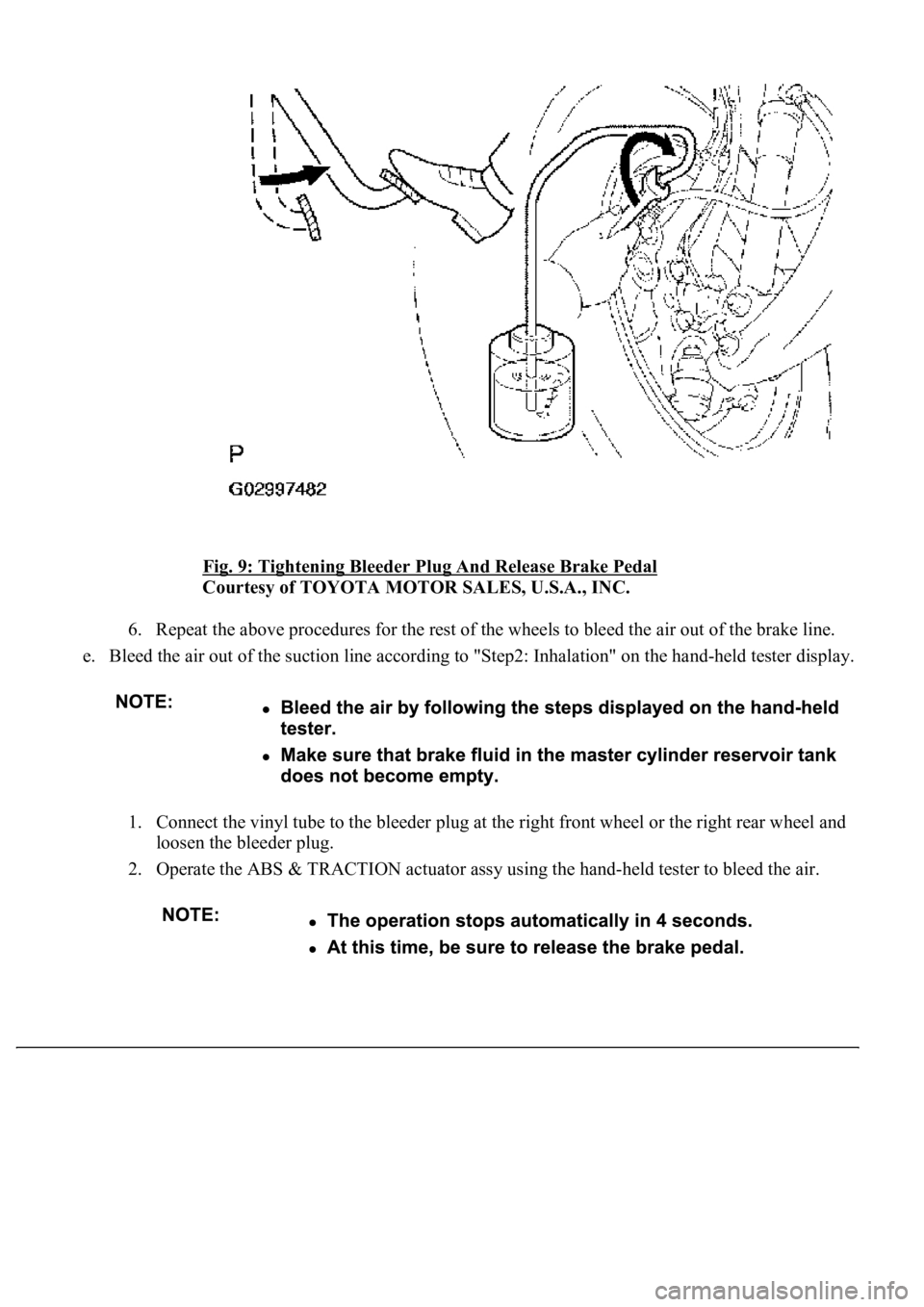
Fig. 9: Tightening Bleeder Plug And Release Brake Pedal
Courtesy of TOYOTA MOTOR SALES, U.S.A., INC.
6. Repeat the above procedures for the rest of the wheels to bleed the air out of the brake line.
e. Bleed the air out of the suction line according to "Step2: Inhalation" on the hand-held tester display.
1. Connect the vinyl tube to the bleeder plug at the right front wheel or the right rear wheel and
loosen the bleeder plug.
2. Operate the ABS & TRACTION actuator assy using the hand-held tester to bleed the air.
Page 973 of 4500
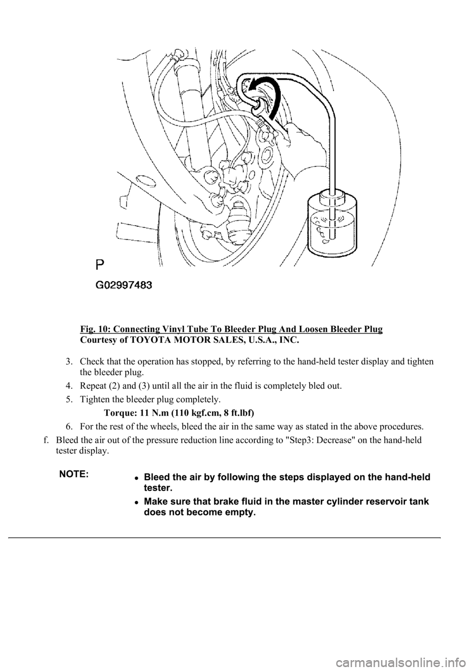
Fig. 10: Connecting Vinyl Tube To Bleeder Plug And Loosen Bleeder Plug
Courtesy of TOYOTA MOTOR SALES, U.S.A., INC.
3. Check that the operation has stopped, by referring to the hand-held tester display and tighten
the bleeder plug.
4. Repeat (2) and (3) until all the air in the fluid is completely bled out.
5. Tighten the bleeder plug completely.
Torque: 11 N.m (110 kgf.cm, 8 ft.lbf)
6. For the rest of the wheels, bleed the air in the same way as stated in the above procedures.
f. Bleed the air out of the pressure reduction line according to "Step3: Decrease" on the hand-held
tester display.
Page 976 of 4500
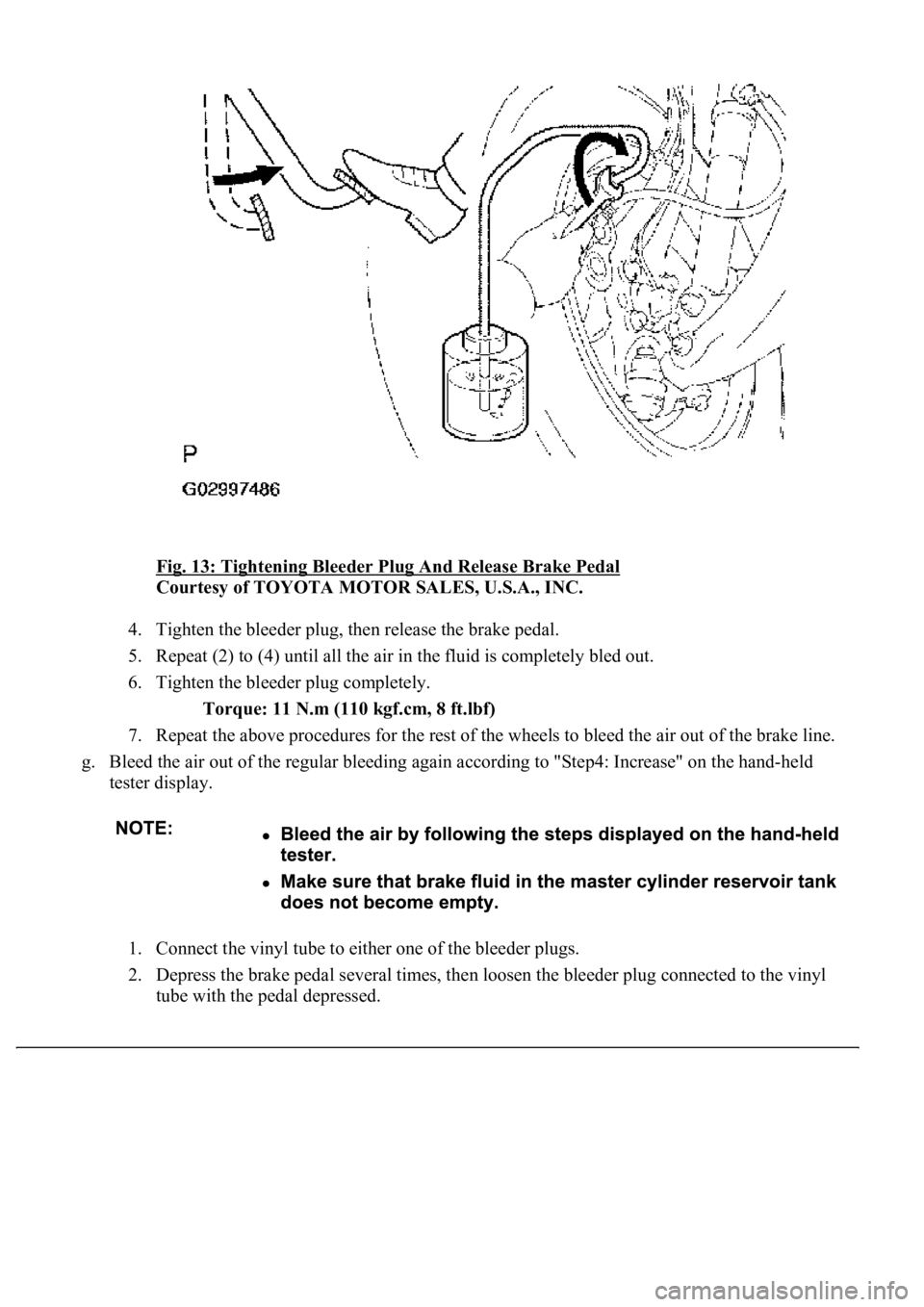
Fig. 13: Tightening Bleeder Plug And Release Brake Pedal
Courtesy of TOYOTA MOTOR SALES, U.S.A., INC.
4. Tighten the bleeder plug, then release the brake pedal.
5. Repeat (2) to (4) until all the air in the fluid is completely bled out.
6. Tighten the bleeder plug completely.
Torque: 11 N.m (110 kgf.cm, 8 ft.lbf)
7. Repeat the above procedures for the rest of the wheels to bleed the air out of the brake line.
g. Bleed the air out of the regular bleeding again according to "Step4: Increase" on the hand-held
tester display.
1. Connect the vinyl tube to either one of the bleeder plugs.
2. Depress the brake pedal several times, then loosen the bleeder plug connected to the vinyl
tube with the pedal depressed.
Page 977 of 4500
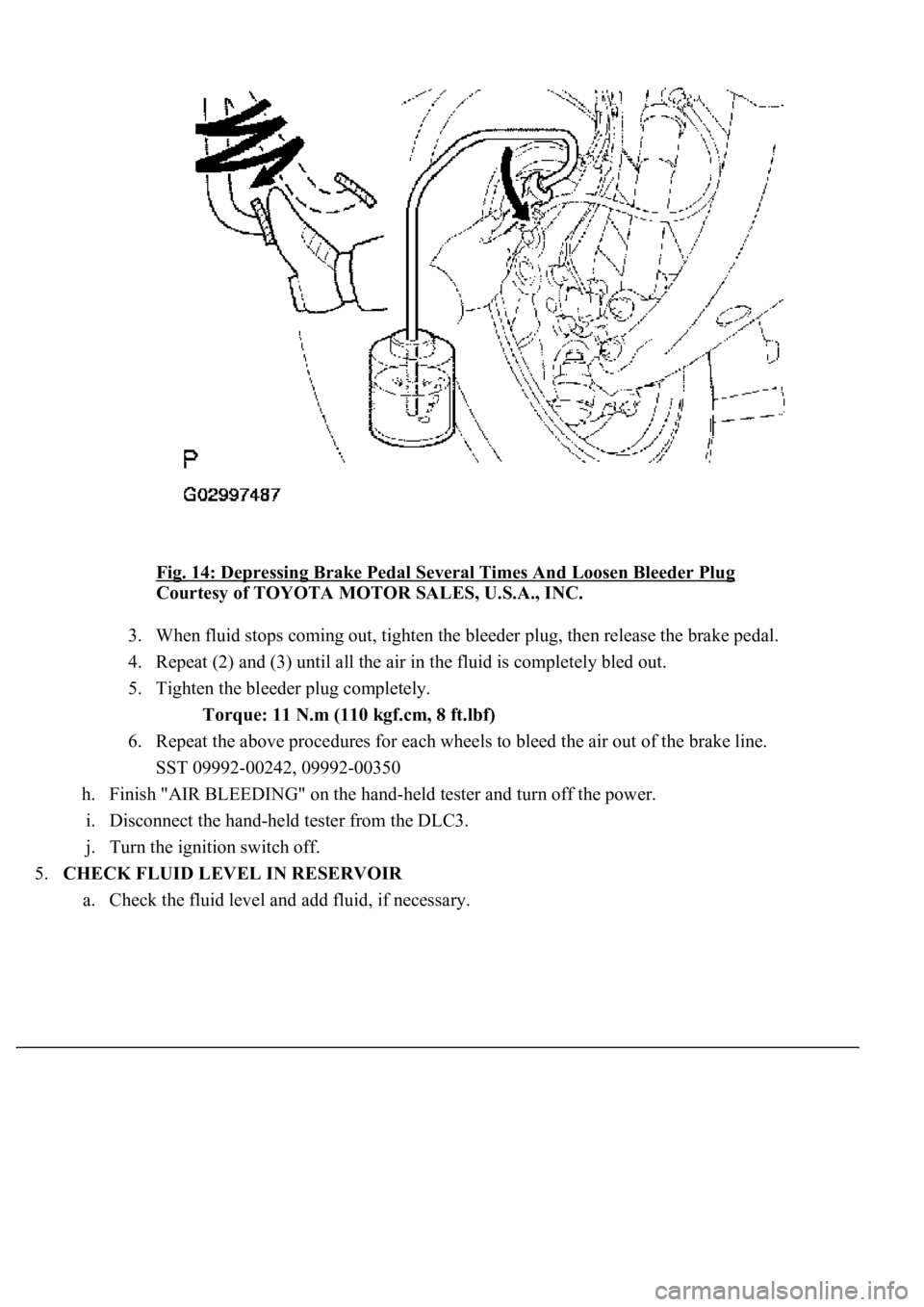
Fig. 14: Depressing Brake Pedal Several Times And Loosen Bleeder Plug
Courtesy of TOYOTA MOTOR SALES, U.S.A., INC.
3. When fluid stops coming out, tighten the bleeder plug, then release the brake pedal.
4. Repeat (2) and (3) until all the air in the fluid is completely bled out.
5. Tighten the bleeder plug completely.
Torque: 11 N.m (110 kgf.cm, 8 ft.lbf)
6. Repeat the above procedures for each wheels to bleed the air out of the brake line.
SST 09992-00242, 09992-00350
h. Finish "AIR BLEEDING" on the hand-held tester and turn off the power.
i. Disconnect the hand-held tester from the DLC3.
j. Turn the ignition switch off.
5.CHECK FLUID LEVEL IN RESERVOIR
a. Check the fluid level and add fluid, if necessar
y.
Page 985 of 4500
23.INSTALL OUTER MIRROR SWITCH ASSY
24.INSTALL COIN BOX
25.INSTALL INSTRUMENT PANEL UNDER COVER NO.1 (SEE REPLACEMENT
)
26.INSTALL CLUSTER FINISH PANEL CENTER LOWER
27.INSTALL INSTRUMENT CLUSTER FINISH PANEL END
28.INSTALL SEAT ASSY FR LH
29.INSTALL SEAT TRACK BRACKET COVER INNER FRONT
30.INSTALL SEAT TRACK BRACKET COVER OUTER FRONT
31.INSTALL SEAT TRACK OUTER COVER LH
32.INSTALL SEAT TRACK COVER RH
33.INSTALL SEAT BELT ANCHOR COVER CAP LH
OVERHAUL
1.DISCONNECT BATTERY NEGATIVE TERMINAL
2.PLACE FRONT WHEELS FACING STRAIGHT AHEAD
3.REMOVE SWITCH & VOLUME CASE
4.REMOVE STEERING WHEEL COVER LOWER NO.2
5.REMOVE HORN BUTTON ASSY (SEE OVERHAUL
)
6.REMOVE STEERING WHEEL ASSY (SEE OVERHAUL
)
<00360036003700030013001c001c001800130010001800130013001400160003000b0013001c001c00180014001000130018001300140013000f00030013001c001c00180015001000130018001300140013000f00030013001c001c001800160010001300
18001300150013000f00030013001c001c0018001700100013[5021)
7.REMOVE STEERING COLUMN COVER (SEE OVERHAUL
)
8.REMOVE SPIRAL CABLE SUB-ASSY (SEE REPLACEMENT
)
9.REMOVE TURN SIGNAL SWITCH ASSY (SEE REPLACEMENT
)
10.REMOVE INSTRUMENT CLUSTER FINISH PANEL CENTER LOWER
11.REMOVE INSTRUMENT CLUSTER FINISH PANEL END
12.REMOVE INSTRUMENT PANEL UNDER COVER SUB-ASSY NO.1 (SEE REPLACEMENT
)
13.REMOVE COIN BOX ASSY
14.REMOVE OUTER MIRROR SWITCH ASSY
15.REMOVE INSTRUMENT PANEL SAFETY PAD SUB-ASSY NO.1 (SEE REPLACEMENT
)
16.REMOVE INSTRUMENT PANEL AIR BAG ASSY LOWER NO.1 (SEE REPLACEMENT
)
17.REMOVE INSTRUMENT PANEL UNDER COVER SUB-ASSY NO.2 (SEE REPLACEMENT
)
18.REMOVE INSTRUMENT CLUSTER FINISH PANEL (SEE REPLACEMENT
)
19.REMOVE COMBINATION METER ASSY (SEE OVERHAUL
)
20.REMOVE PUSH ROD PIN
a. Disconnect the stop lamp switch connector and brake pedal load sensing switch connector.
Page 1005 of 4500

34.CHECK AND ADJUST BRAKE PEDAL HEIGHT (SEE ON-VEHICLE INSPECTION )
35.CHECK PEDAL FREE PLAY (SEE ON
-VEHICLE INSPECTION )
36.CHECK PEDAL RESERVE DISTANCE (SEE ON
-VEHICLE INSPECTION )
37.INSTALL COMBINATION METER ASSY (SEE OVERHAUL
)
38.INSTALL INSTRUMENT CLUSTER FINISH PANEL (SEE REPLACEMENT
)
39.INSTALL INSTRUMENT PANEL UNDER COVER SUB-ASSY NO.2 (SEE REPLACEMENT
)
40.INSTALL INSTRUMENT PANEL AIR BAG ASSY LOWER NO.1 (SEE REPLACEMENT
)
41.INSTALL INSTRUMENT PANEL SAFETY PAD SUB-ASSY NO.1 (SEE REPLACEMENT
)
42.INSTALL OUTER MIRROR SWITCH ASSY
43.INSTALL COIN BOX ASSY
44.INSTALL INSTRUMENT PANEL UNDER COVER SUB-ASSY NO.1 (SEE REPLACEMENT
)
45.INSTALL INSTRUMENT CLUSTER FINISH PANEL CENTER LOWER
46.INSTALL INSTRUMENT CLUSTER FINISH PANEL END
47.INSTALL TURN SIGNAL SWITCH ASSY (SEE REPLACEMENT
)
48.INSTALL SPIRAL CABLE SUB-ASSY (SEE REPLACEMENT
)
49.INSTALL STEERING COLUMN COVER (SEE OVERHAUL
)
50.INSTALL STEERING WHEEL ASSY (SEE OVERHAUL
)
<00360036003700030013001c001c001800130010001800130013001400160003000b0013001c001c00180014001000130018001300140013000f00030013001c001c00180015001000130018001300140013000f00030013001c001c001800160010001300
18001300150013000f00030013001c001c0018001700100013[5021)
51.INSTALL HORN BUTTON ASSY (SEE OVERHAUL
)
52.INSTALL STEERING WHEEL COVER LOWER NO.2
53.INSTALL SWITCH & VOLUME CASE
54.CONNECT BATTERY NEGATIVE TERMINAL
55.INSPECT SRS WARNING LIGHT (SEE DIAGNOSIS SYSTEM
)
56.PERFORM INITIALIZATION (SEE PRECAUTION
)
OVERHAUL
1.REMOVE ENGINE ROOM SIDE COVER
2.SEPARATE ENGINE ROOM NO.3 R/B
a. Remove the bolt and separate the engine room No.3 R/B.
3.DRAIN BRAKE FLUID
a. Draw out fluid with syringe.
4.REMOVE BRAKE MASTER CYLINDER SUB-ASSY
a. Remove the clamp from the 2 brake tubes.
Page 1039 of 4500
1.REMOVE FRONT WHEEL
2.DRAIN BRAKE FLUID
a. Draw out fluid with syringe.
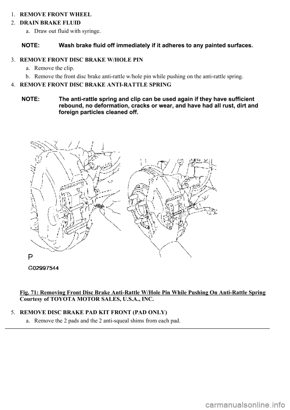
3.REMOVE FRONT DISC BRAKE W/HOLE PIN
a. Remove the clip.
b. Remove the front disc brake anti-rattle w/hole pin while pushing on the anti-rattle spring.
4.REMOVE FRONT DISC BRAKE ANTI-RATTLE SPRING
Fig. 71: Removing Front Disc Brake Anti
-Rattle W/Hole Pin While Pushing On Anti-Rattle Spring
Courtesy of TOYOTA MOTOR SALES, U.S.A., INC.
5.REMOVE DISC BRAKE PAD KIT FRONT (PAD ONLY)
a. Remove the 2 pads and the 2 anti-squeal shims from each pad.
Page 1040 of 4500
b. Right wheel:
Remove the clamp, clip and bleeder plug cap, and disconnect the pad wear indicator assembly from the
inner pad.
Fig. 72: Removing Pads And Anti
-Squeal Shims From Pad
Courtesy of TOYOTA MOTOR SALES, U.S.A., INC.
6.INSPECT PAD LINING THICKNESS
a. Using a ruler, measure the pad lining thickness.
Standard thickness: 11.0 mm (0.433 in.)
Minimum thickness: 1.0 mm (0.039 in.)
If the pad linin
g thickness is less than the minimum, replace the pad.
Page 1053 of 4500
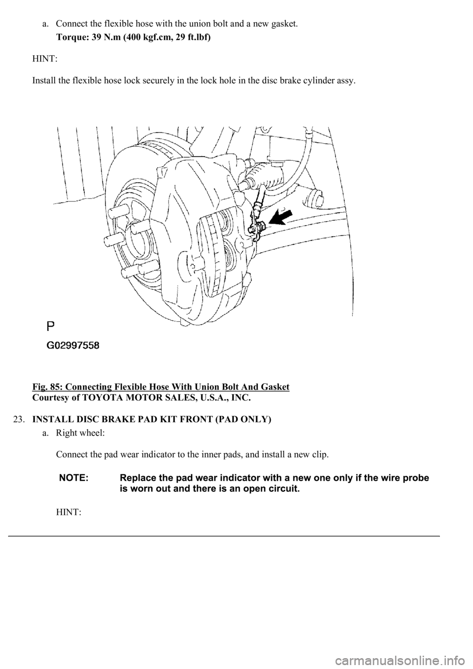
a. Connect the flexible hose with the union bolt and a new gasket.
Torque: 39 N.m (400 kgf.cm, 29 ft.lbf)
HINT:
Install the flexible hose lock securely in the lock hole in the disc brake cylinder assy.
Fig. 85: Connecting Flexible Hose With Union Bolt And Gasket
Courtesy of TOYOTA MOTOR SALES, U.S.A., INC.
23.INSTALL DISC BRAKE PAD KIT FRONT (PAD ONLY)
a. Right wheel:
Connect the pad wear indicator to the inner pads, and install a new clip.
HINT: