wheel LEXUS LS430 2003 Factory Owner's Guide
[x] Cancel search | Manufacturer: LEXUS, Model Year: 2003, Model line: LS430, Model: LEXUS LS430 2003Pages: 4500, PDF Size: 87.45 MB
Page 495 of 4500

Fig. 17: Diagnostic Trouble Code Information Chart (2 Of 2)
Courtesy of TOYOTA MOTOR SALES, U.S.A., INC.
*1: For codes in the "Indicator Light" column with a "circ" mark, the absorber control indicator lamp blinks at 1
second intervals.
*2: For codes in the "Indicator Light" column with a " (xcirc)" mark, when trouble occurs, "HEIGHT HI" is
displayed on the multi-information display. Also, the master warning light is lit on the combination meter and
an alarm sounds.
*3: Since the relief pressure of the compressed air is 980 kPa (10 kgf/cm
2 , 142 psi), if vehicle height control is
attempted on a steeply sloping road, when the vehicle is overloaded, or when the vehicle height is jacked up
with the engine running, code "C1751" may be output and vehicle height control may be suspended. (This is not
abnormal.) In this case, however, when detecting the first error, approximately 10 minutes after the ignition
switch was turned to the ON position, vehicle height control is resumed. When the following errors are
detected, it takes 70 minutes until the control is resumed.
*4: If vehicle height control is operated while the wheels are removed or the vehicle is jacked up, code "C1752"
may be output, but this is not abnormal. When code "C1752" is output, vehicle height control is not carried out.
However, control is resumed if the ignition switch is turned off, then to the ON position again.
CIRCUIT DESCRIPTION
The height control sensor sub-assy controls the resistance value by following changes in vehicle height. The
suspension control ECU detects the change in vehicle height from the transformed voltage. The suspension
control ECU outputs a constant voltage of 5 V to the SHB terminal of the height control sensor sub-assy.
In the height control sensor, the voltage is changed due to resistance. The changed voltage is output from the
Page 555 of 4500
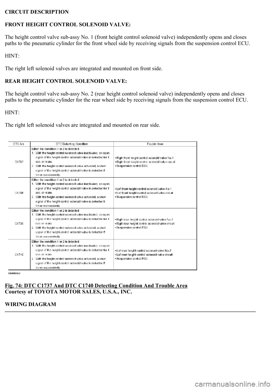
CIRCUIT DESCRIPTION
FRONT HEIGHT CONTROL SOLENOID VALVE:
The height control valve sub-assy No. 1 (front height control solenoid valve) independently opens and closes
paths to the pneumatic cylinder for the front wheel side by receiving signals from the suspension control ECU.
HINT:
The right left solenoid valves are integrated and mounted on front side.
REAR HEIGHT CONTROL SOLENOID VALVE:
The height control valve sub-assy No. 2 (rear height control solenoid valve) independently opens and closes
paths to the pneumatic cylinder for the rear wheel side by receiving signals from the suspension control ECU.
HINT:
The right left solenoid valves are integrated and mounted on rear side.
Fig. 74: DTC C1737 And DTC C1740 Detecting Condition And Trouble Area
Courtesy of TOYOTA MOTOR SALES, U.S.A., INC.
WIRING DIAGRAM
Page 605 of 4500

Fig. 120: Identifying Suspension Control ECU Connector Terminals
Courtesy of TOYOTA MOTOR SALES, U.S.A., INC.
NG: REPAIR OR REPLACE HARNESS OR CONNECTOR
OK: REPLACE SUSPENSION CONTROL ECU (SEE REPLACEMENT
)
CIRCUIT DESCRIPTION
The speed sensors monitors the speed of the wheels, and sends an appropriate speed signals to the suspension
control ECU through the brake actuator assy (skid control ECU).
If trouble occurs in either the right rear speed sensor or left rear speed sensor, DTC (C1776) is output.
Page 606 of 4500
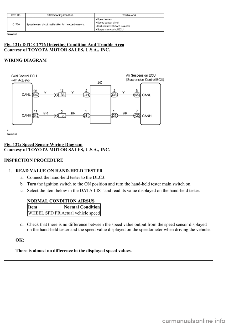
Fig. 121: DTC C1776 Detecting Condition And Trouble Area
Courtesy of TOYOTA MOTOR SALES, U.S.A., INC.
WIRING DIAGRAM
Fig. 122: Speed Sensor Wiring Diagram
Courtesy of TOYOTA MOTOR SALES, U.S.A., INC.
INSPECTION PROCEDURE
1.READ VALUE ON HAND-HELD TESTER
a. Connect the hand-held tester to the DLC3.
b. Turn the ignition switch to the ON position and turn the hand-held tester main switch on.
c. Select the item below in the DATA LIST and read its value displayed on the hand-held tester.
NORMAL CONDITION AIRSUS
d. Check that there is no difference between the speed value output from the speed sensor displayed
on the hand-held tester and the speed value displayed on the speedometer when driving the vehicle.
OK:
There is almost no difference in the displayed speed values.
ItemNormal Condition
WHEEL SPD FRActual vehicle speed
Page 609 of 4500
b. Turn the ignition switch to the ON position and turn the hand-held tester main switch on.
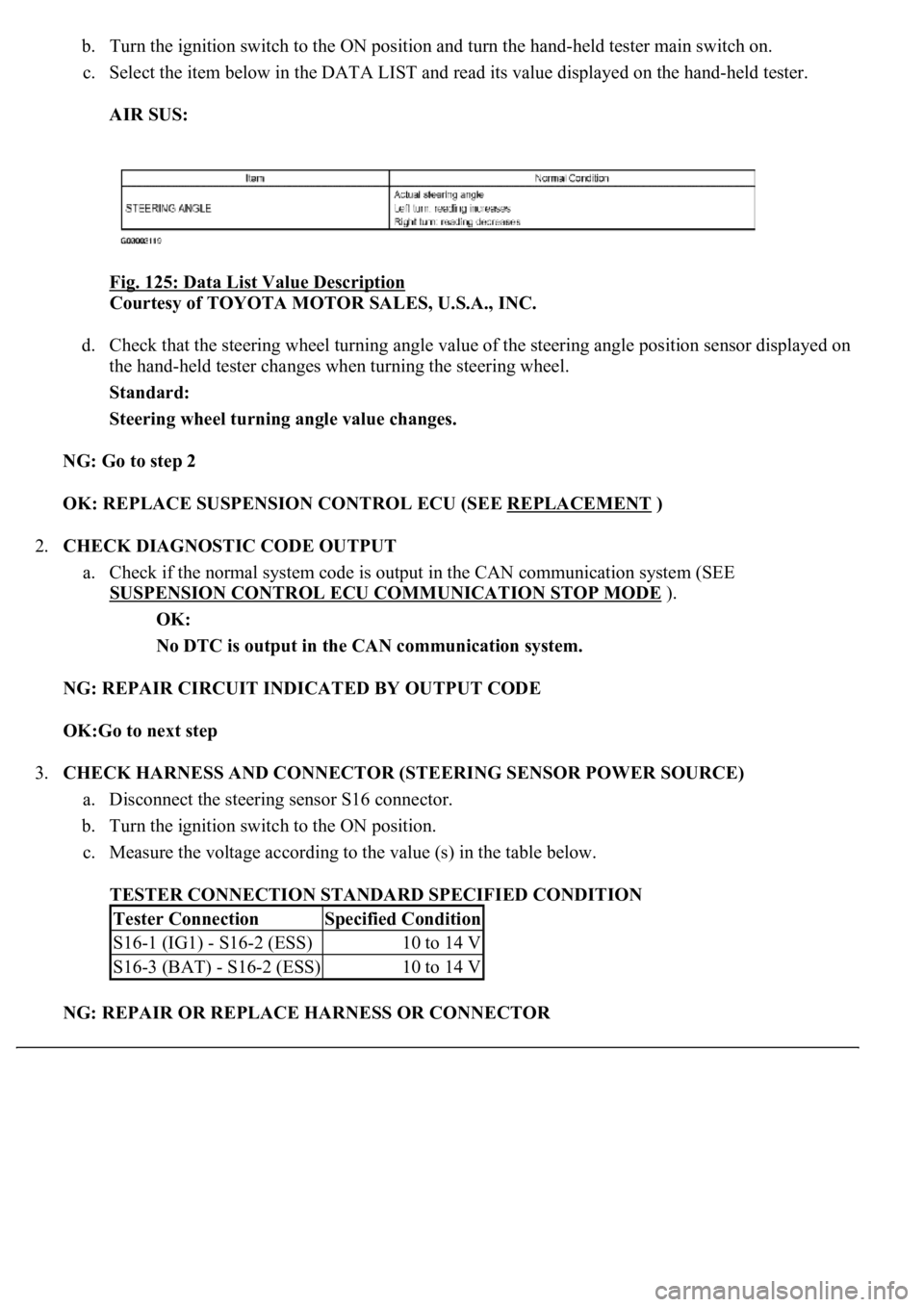
c. Select the item below in the DATA LIST and read its value displayed on the hand-held tester.
AIR SUS:
Fig. 125: Data List Value Description
Courtesy of TOYOTA MOTOR SALES, U.S.A., INC.
d. Check that the steering wheel turning angle value of the steering angle position sensor displayed on
the hand-held tester changes when turning the steering wheel.
Standard:
Steering wheel turning angle value changes.
NG: Go to step 2
OK: REPLACE SUSPENSION CONTROL ECU (SEE REPLACEMENT
)
2.CHECK DIAGNOSTIC CODE OUTPUT
a. Check if the normal system code is output in the CAN communication system (SEE
SUSPENSION CONTROL ECU COMMUNICATION STOP MODE
).
OK:
No DTC is output in the CAN communication system.
NG: REPAIR CIRCUIT INDICATED BY OUTPUT CODE
OK:Go to next step
3.CHECK HARNESS AND CONNECTOR (STEERING SENSOR POWER SOURCE)
a. Disconnect the steering sensor S16 connector.
b. Turn the ignition switch to the ON position.
c. Measure the voltage according to the value (s) in the table below.
TESTER CONNECTION STANDARD SPECIFIED CONDITION
NG: REPAIR OR REPLACE HARNESS OR CONNECTOR
Tester ConnectionSpecified Condition
S16-1 (IG1) - S16-2 (ESS)10 to 14 V
S16-3 (BAT) - S16-2 (ESS)10 to 14 V
Page 678 of 4500

Fig. 40: Disengaging Claws
Courtesy of TOYOTA MOTOR SALES, U.S.A., INC.
2.REMOVE STEERING WHEEL COVER LOWER NO. 2 (See step 4 on REPLACEMENT
)
3.REMOVE HORN BUTTON ASSY (See step 5 on REPLACEMENT
)
4.REMOVE STEERING PAD SWITCH MODULATOR
a. Remove the 4 screws.
b. Disconnect the connectors and remove the steering pad switch modulator.
Page 788 of 4500

Fig. 70: Identifying Combination Meter Assembly Connector
Courtesy of TOYOTA MOTOR SALES, U.S.A., INC.
OK: Go to next step
2.INSPECT COMBINATION METER ASSY
a. Check the voltage.
1. Jack up either of the front wheels.
2. Adjust the shift lever to the neutral position.
3. Measure the voltage between the terminals +S and body ground while turning the front wheel
slowly.
Standard:
Page 851 of 4500
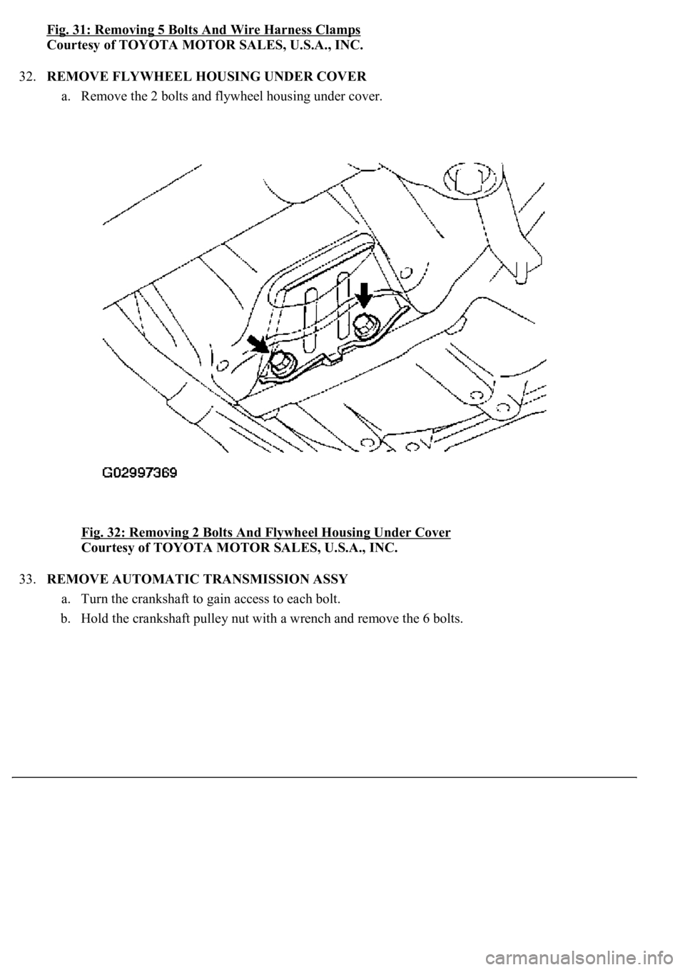
Fig. 31: Removing 5 Bolts And Wire Harness Clamps
Courtesy of TOYOTA MOTOR SALES, U.S.A., INC.
32.REMOVE FLYWHEEL HOUSING UNDER COVER
a. Remove the 2 bolts and flywheel housing under cover.
Fig. 32: Removing 2 Bolts And Flywheel Housing Under Cover
Courtesy of TOYOTA MOTOR SALES, U.S.A., INC.
33.REMOVE AUTOMATIC TRANSMISSION ASSY
a. Turn the crankshaft to gain access to each bolt.
b. Hold the crankshaft pulley nut with a wrench and remove the 6 bolts.
Page 866 of 4500
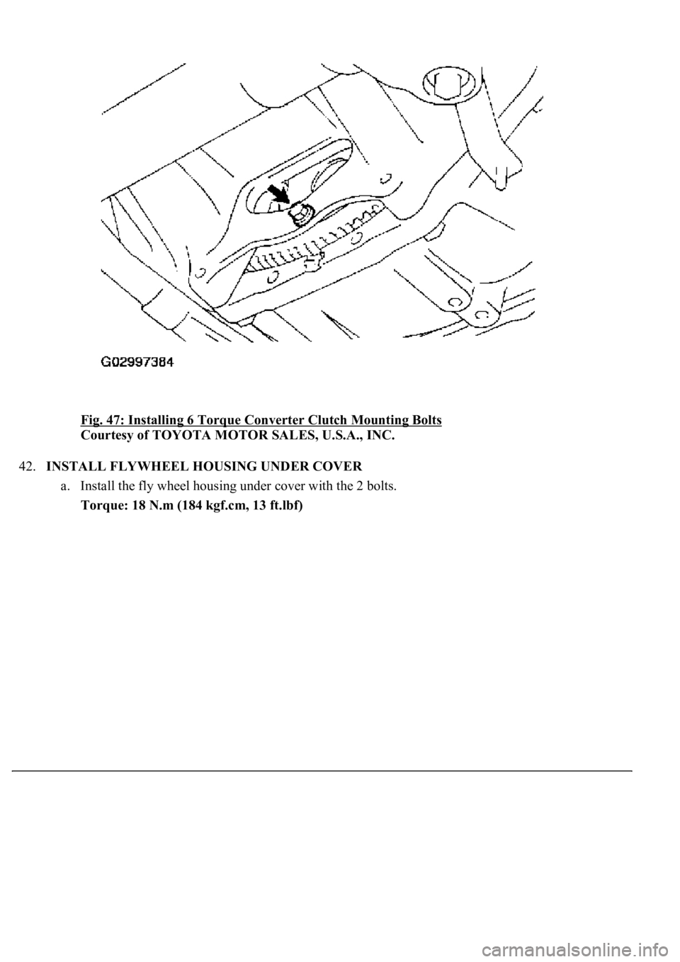
Fig. 47: Installing 6 Torque Converter Clutch Mounting Bolts
Courtesy of TOYOTA MOTOR SALES, U.S.A., INC.
42.INSTALL FLYWHEEL HOUSING UNDER COVER
a. Install the fly wheel housing under cover with the 2 bolts.
Torque: 18 N.m (184 kgf.cm, 13 ft.lbf)
Page 867 of 4500
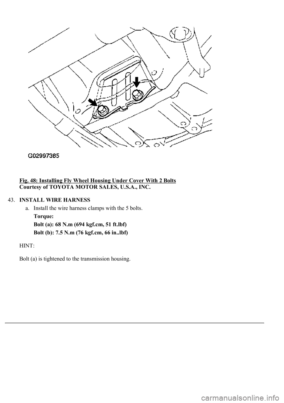
Fig. 48: Installing Fly Wheel Housing Under Cover With 2 Bolts
Courtesy of TOYOTA MOTOR SALES, U.S.A., INC.
43.INSTALL WIRE HARNESS
a. Install the wire harness clamps with the 5 bolts.
Torque:
Bolt (a): 68 N.m (694 kgf.cm, 51 ft.lbf)
Bolt (b): 7.5 N.m (76 kgf.cm, 66 in..lbf)
HINT:
Bolt (a) is ti
ghtened to the transmission housing.