Modulated LEXUS LS430 2003 Factory Repair Manual
[x] Cancel search | Manufacturer: LEXUS, Model Year: 2003, Model line: LS430, Model: LEXUS LS430 2003Pages: 4500, PDF Size: 87.45 MB
Page 1200 of 4500
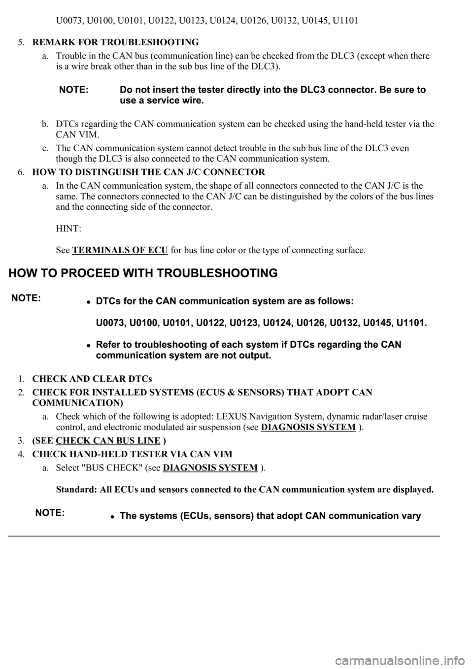
U0073, U0100, U0101, U0122, U0123, U0124, U0126, U0132, U0145, U1101
5.REMARK FOR TROUBLESHOOTING
a. Trouble in the CAN bus (communication line) can be checked from the DLC3 (except when there
is a wire break other than in the sub bus line of the DLC3).
b. DTCs regarding the CAN communication system can be checked using the hand-held tester via the
CAN VIM.
c. The CAN communication system cannot detect trouble in the sub bus line of the DLC3 even
though the DLC3 is also connected to the CAN communication system.
6.HOW TO DISTINGUISH THE CAN J/C CONNECTOR
a. In the CAN communication system, the shape of all connectors connected to the CAN J/C is the
same. The connectors connected to the CAN J/C can be distinguished by the colors of the bus lines
and the connecting side of the connector.
HINT:
See TERMINALS OF ECU
for bus line color or the type of connecting surface.
1.CHECK AND CLEAR DTCs
2.CHECK FOR INSTALLED SYSTEMS (ECUS & SENSORS) THAT ADOPT CAN
COMMUNICATION)
a. Check which of the following is adopted: LEXUS Navigation System, dynamic radar/laser cruise
control, and electronic modulated air suspension (see DIAGNOSIS SYSTEM
).
3.(SEE CHECK CAN BUS LINE
)
4.CHECK HAND-HELD TESTER VIA CAN VIM
a. Select "BUS CHECK" (see DIAGNOSIS SYSTEM
).
Standard: All ECUs and sensors connected to the CAN communication system are displayed.
Page 1204 of 4500
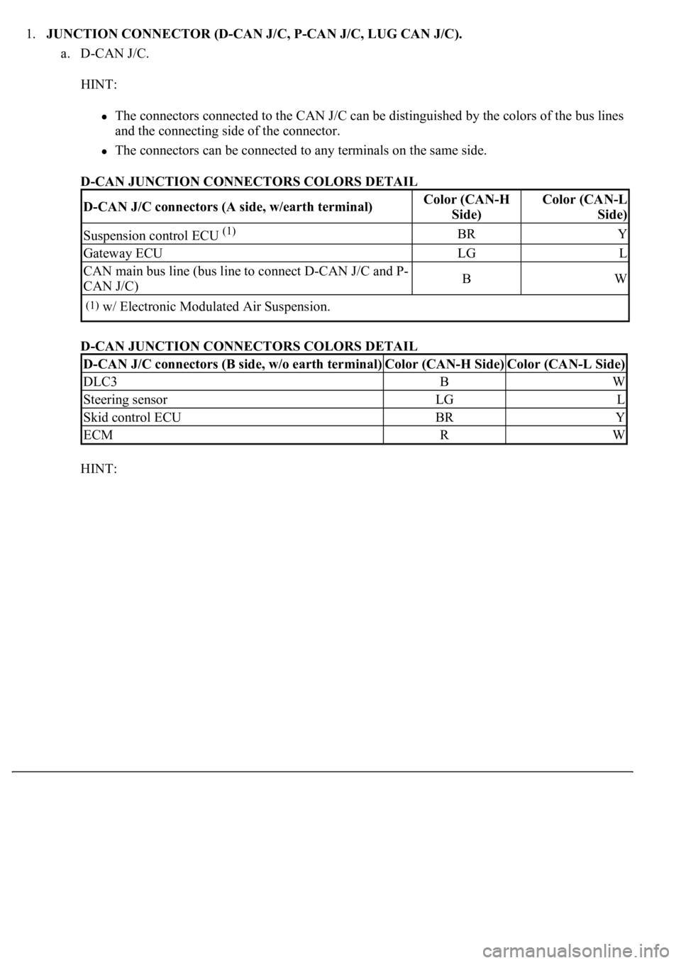
1.JUNCTION CONNECTOR (D-CAN J/C, P-CAN J/C, LUG CAN J/C).
a. D-CAN J/C.
HINT:
The connectors connected to the CAN J/C can be distinguished by the colors of the bus lines
and the connecting side of the connector.
<0037004b00480003004600520051005100480046005700520055005600030046004400510003004500480003004600520051005100480046005700480047000300570052000300440051005c00030057004800550050004c00510044004f00560003005200
5100030057004b00480003005600440050004800030056004c[de.
D-CAN JUNCTION CONNECTORS COLORS DETAIL
D-CAN JUNCTION CONNECTORS COLORS DETAIL
HINT:
D-CAN J/C connectors (A side, w/earth terminal)Color (CAN-H
Side)Color (CAN-L
Side)
Suspension control ECU (1)BRY
Gateway ECULGL
CAN main bus line (bus line to connect D-CAN J/C and P-
CAN J/C)BW
(1)w/ Electronic Modulated Air Suspension.
D-CAN J/C connectors (B side, w/o earth terminal)Color (CAN-H Side)Color (CAN-L Side)
DLC3BW
Steering sensorLGL
Skid control ECUBRY
ECMRW
Page 1224 of 4500
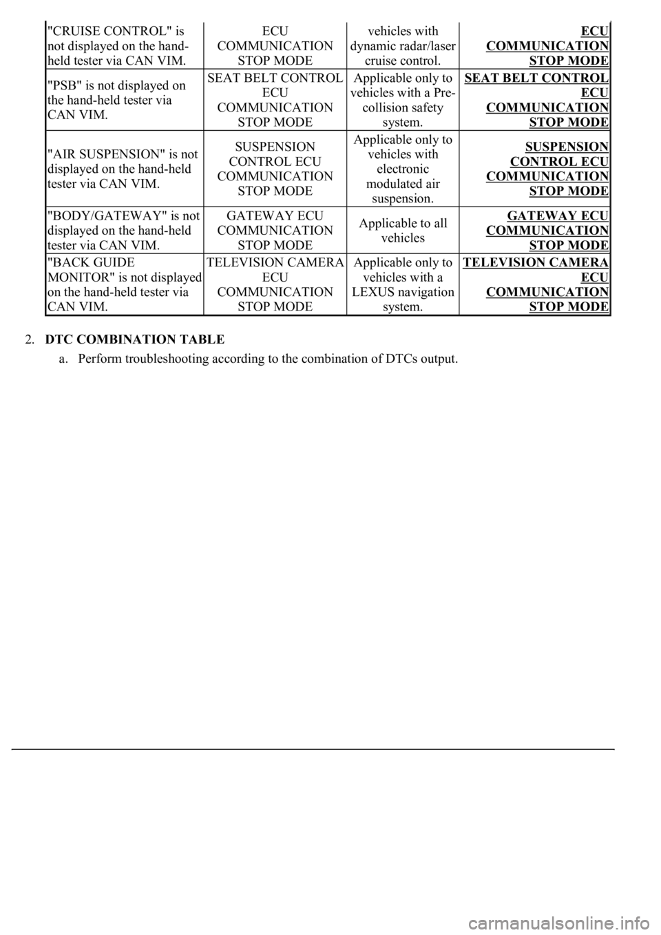
2.DTC COMBINATION TABLE
a. Perform troubleshooting according to the combination of DTCs output.
"CRUISE CONTROL" is
not displayed on the hand-
held tester via CAN VIM.ECU
COMMUNICATION
STOP MODEvehicles with
dynamic radar/laser
cruise control.ECU
COMMUNICATION
STOP MODE
"PSB" is not displayed on
the hand-held tester via
CAN VIM.SEAT BELT CONTROL
ECU
COMMUNICATION
STOP MODEApplicable only to
vehicles with a Pre-
collision safety
system.SEAT BELT CONTROL
ECU
COMMUNICATION
STOP MODE
"AIR SUSPENSION" is not
displayed on the hand-held
tester via CAN VIM.SUSPENSION
CONTROL ECU
COMMUNICATION
STOP MODEApplicable only to
vehicles with
electronic
modulated air
suspension.SUSPENSION
CONTROL ECU
COMMUNICATION
STOP MODE
"BODY/GATEWAY" is not
displayed on the hand-held
tester via CAN VIM.GATEWAY ECU
COMMUNICATION
STOP MODEApplicable to all
vehiclesGATEWAY ECU
COMMUNICATION
STOP MODE
"BACK GUIDE
MONITOR" is not displayed
on the hand-held tester via
CAN VIM.TELEVISION CAMERA
ECU
COMMUNICATION
STOP MODEApplicable only to
vehicles with a
LEXUS navigation
system.TELEVISION CAMERA
ECU
COMMUNICATION
STOP MODE
Page 3181 of 4500
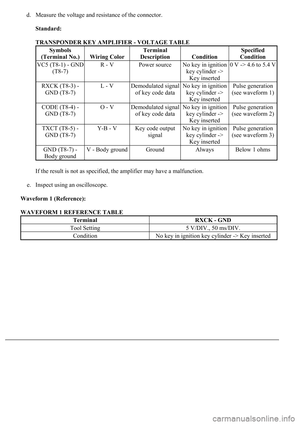
d. Measure the voltage and resistance of the connector.
Standard:
TRANSPONDER KEY AMPLIFIER - VOLTAGE TABLE
If the result is not as specified, the amplifier may have a malfunction.
e. Inspect using an oscilloscope.
Waveform 1 (Reference):
WAVEFORM 1 REFERENCE TABLE
Symbols
(Terminal No.)
Wiring Color
Terminal
Description
Condition
Specified
Condition
VC5 (T8-1) - GND
(T8-7)R - VPower sourceNo key in ignition
key cylinder ->
Key inserted0 V -> 4.6 to 5.4 V
RXCK (T8-3) -
GND (T8-7)L - VDemodulated signal
of key code dataNo key in ignition
key cylinder ->
Key insertedPulse generation
(see waveform 1)
CODE (T8-4) -
GND (T8-7)O - VDemodulated signal
of key code dataNo key in ignition
key cylinder ->
Key insertedPulse generation
(see waveform 2)
TXCT (T8-5) -
GND (T8-7)Y-B - VKey code output
signalNo key in ignition
key cylinder ->
Key insertedPulse generation
(see waveform 3)
GND (T8-7) -
Body groundV - Body groundGroundAlwaysBelow 1 ohms
TerminalRXCK - GND
Tool Setting5 V/DIV., 50 ms/DIV.
ConditionNo key in ignition key cylinder -> Key inserted
Page 3239 of 4500
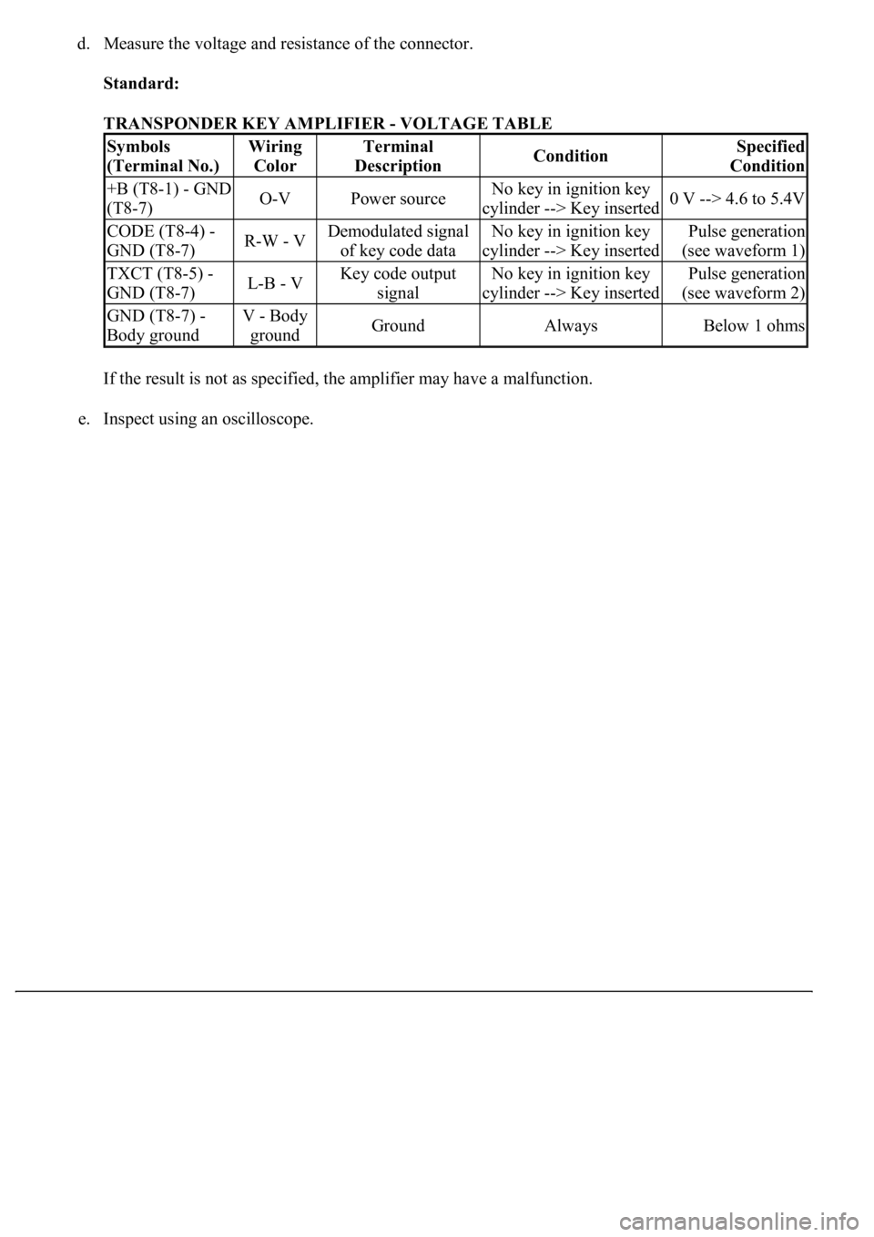
d. Measure the voltage and resistance of the connector.
Standard:
TRANSPONDER KEY AMPLIFIER - VOLTAGE TABLE
If the result is not as specified, the amplifier may have a malfunction.
e. Inspect using an oscilloscope.
Symbols
(Terminal No.)Wiring
ColorTerminal
DescriptionConditionSpecified
Condition
+B (T8-1) - GND
(T8-7)O-VPower sourceNo key in ignition key
cylinder --> Key inserted0 V --> 4.6 to 5.4V
CODE (T8-4) -
GND (T8-7)R-W - VDemodulated signal
of key code dataNo key in ignition key
cylinder --> Key insertedPulse generation
(see waveform 1)
TXCT (T8-5) -
GND (T8-7)L-B - VKey code output
signalNo key in ignition key
cylinder --> Key insertedPulse generation
(see waveform 2)
GND (T8-7) -
Body groundV - Body
groundGroundAlwaysBelow 1 ohms
Page 4003 of 4500
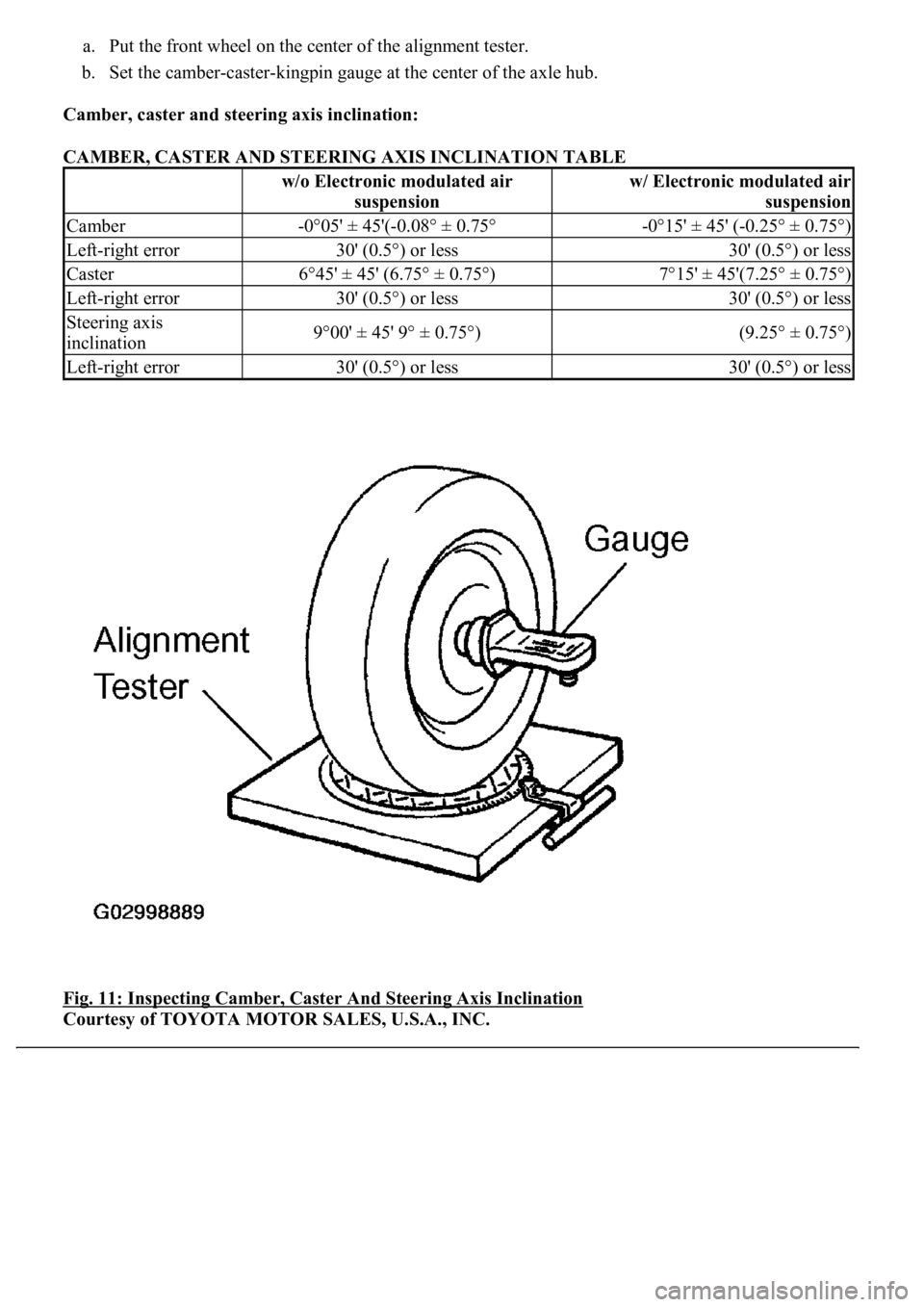
a. Put the front wheel on the center of the alignment tester.
b. Set the camber-caster-kingpin gauge at the center of the axle hub.
Camber, caster and steering axis inclination:
CAMBER, CASTER AND STEERING AXIS INCLINATION TABLE
Fig. 11: Inspecting Camber, Caster And Steering Axis Inclination
Courtesy of TOYOTA MOTOR SALES, U.S.A., INC.
w/o Electronic modulated air
suspensionw/ Electronic modulated air
suspension
Camber-0°05' ± 45'(-0.08° ± 0.75°-0°15' ± 45' (-0.25° ± 0.75°)
Left-right error30' (0.5°) or less30' (0.5°) or less
Caster6°45' ± 45' (6.75° ± 0.75°)7°15' ± 45'(7.25° ± 0.75°)
Left-right error30' (0.5°) or less30' (0.5°) or less
Steering axis
inclination9°00' ± 45' 9° ± 0.75°)(9.25° ± 0.75°)
Left-right error30' (0.5°) or less30' (0.5°) or less
Page 4166 of 4500
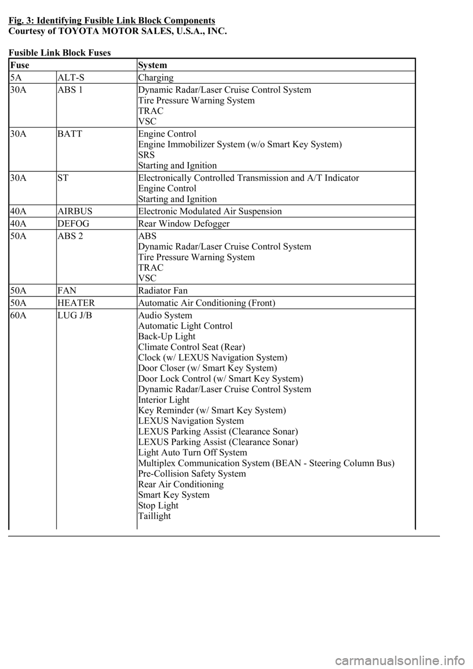
Fig. 3: Identifying Fusible Link Block Components
Courtesy of TOYOTA MOTOR SALES, U.S.A., INC.
Fusible Link Block Fuses
FuseSystem
5AALT-SCharging
30AABS 1Dynamic Radar/Laser Cruise Control System
Tire Pressure Warning System
TRAC
VSC
30ABATTEngine Control
Engine Immobilizer System (w/o Smart Key System)
SRS
Starting and Ignition
30ASTElectronically Controlled Transmission and A/T Indicator
Engine Control
Starting and Ignition
40AAIRBUSElectronic Modulated Air Suspension
40ADEFOGRear Window Defogger
50AABS 2ABS
Dynamic Radar/Laser Cruise Control System
Tire Pressure Warning System
TRAC
VSC
50AFANRadiator Fan
50AHEATERAutomatic Air Conditioning (Front)
60ALUG J/BAudio System
Automatic Light Control
Back-Up Light
Climate Control Seat (Rear)
Clock (w/ LEXUS Navigation System)
Door Closer (w/ Smart Key System)
Door Lock Control (w/ Smart Key System)
Dynamic Radar/Laser Cruise Control System
Interior Light
Key Reminder (w/ Smart Key System)
LEXUS Navigation System
LEXUS Parking Assist (Clearance Sonar)
LEXUS Parking Assist (Clearance Sonar)
Light Auto Turn Off System
Multiplex Communication System (BEAN - Steering Column Bus)
Pre-Collision Safety System
Rear Air Conditioning
Smart Key System
Stop Light
Taillight
Page 4170 of 4500
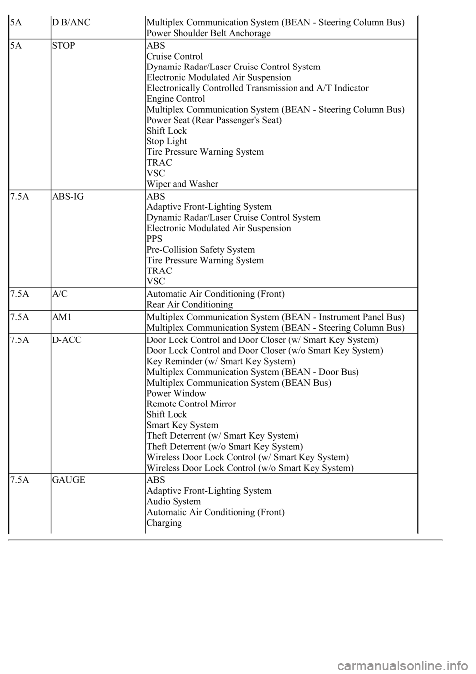
5AD B/ANCMultiplex Communication System (BEAN - Steering Column Bus)
Power Shoulder Belt Anchorage
5ASTOPABS
Cruise Control
Dynamic Radar/Laser Cruise Control System
Electronic Modulated Air Suspension
Electronically Controlled Transmission and A/T Indicator
Engine Control
Multiplex Communication System (BEAN - Steering Column Bus)
Power Seat (Rear Passenger's Seat)
Shift Lock
Stop Light
Tire Pressure Warning System
TRAC
VSC
Wiper and Washer
7.5AABS-IGABS
Adaptive Front-Lighting System
Dynamic Radar/Laser Cruise Control System
Electronic Modulated Air Suspension
PPS
Pre-Collision Safety System
Tire Pressure Warning System
TRAC
VSC
7.5AA/CAutomatic Air Conditioning (Front)
Rear Air Conditioning
7.5AAM1Multiplex Communication System (BEAN - Instrument Panel Bus)
Multiplex Communication System (BEAN - Steering Column Bus)
7.5AD-ACCDoor Lock Control and Door Closer (w/ Smart Key System)
Door Lock Control and Door Closer (w/o Smart Key System)
Key Reminder (w/ Smart Key System)
Multiplex Communication System (BEAN - Door Bus)
Multiplex Communication System (BEAN Bus)
Power Window
Remote Control Mirror
Shift Lock
Smart Key System
Theft Deterrent (w/ Smart Key System)
Theft Deterrent (w/o Smart Key System)
Wireless Door Lock Control (w/ Smart Key System)
Wireless Door Lock Control (w/o Smart Key System)
7.5AGAUGEABS
Adaptive Front-Lighting System
Audio System
Automatic Air Conditioning (Front)
Charging
Page 4171 of 4500
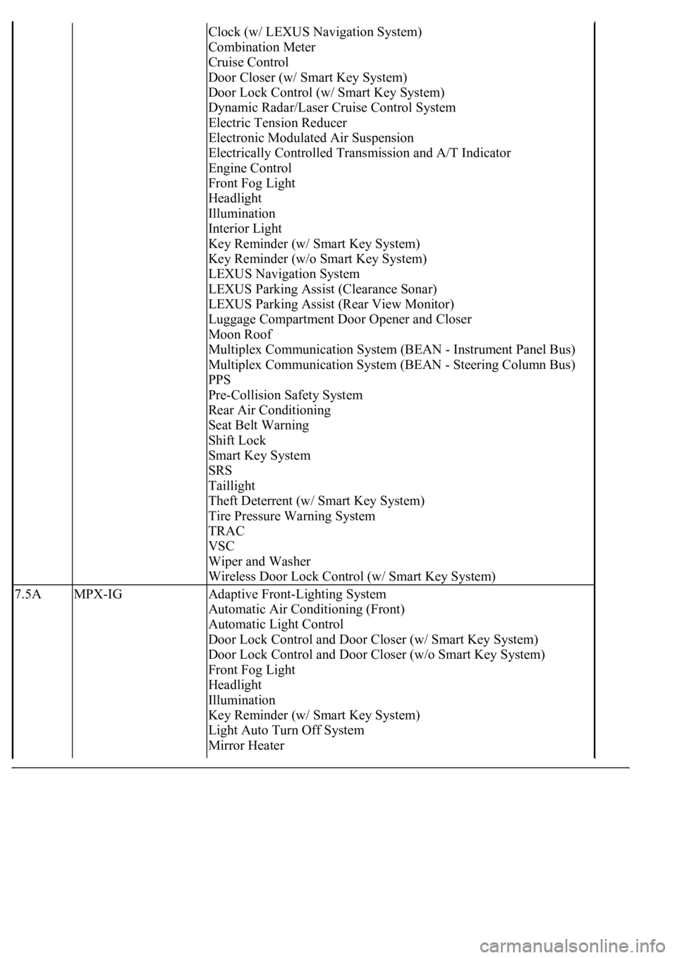
Clock (w/ LEXUS Navigation System)
Combination Meter
Cruise Control
Door Closer (w/ Smart Key System)
Door Lock Control (w/ Smart Key System)
Dynamic Radar/Laser Cruise Control System
Electric Tension Reducer
Electronic Modulated Air Suspension
Electrically Controlled Transmission and A/T Indicator
Engine Control
Front Fog Light
Headlight
Illumination
Interior Light
Key Reminder (w/ Smart Key System)
Key Reminder (w/o Smart Key System)
LEXUS Navigation System
LEXUS Parking Assist (Clearance Sonar)
LEXUS Parking Assist (Rear View Monitor)
Luggage Compartment Door Opener and Closer
Moon Roof
Multiplex Communication System (BEAN - Instrument Panel Bus)
Multiplex Communication System (BEAN - Steering Column Bus)
PPS
Pre-Collision Safety System
Rear Air Conditioning
Seat Belt Warning
Shift Lock
Smart Key System
SRS
Taillight
Theft Deterrent (w/ Smart Key System)
Tire Pressure Warning System
TRAC
VSC
Wiper and Washer
Wireless Door Lock Control (w/ Smart Key System)
7.5AMPX-IGAdaptive Front-Lighting System
Automatic Air Conditioning (Front)
Automatic Light Control
Door Lock Control and Door Closer (w/ Smart Key System)
Door Lock Control and Door Closer (w/o Smart Key System)
Front Fog Light
Headlight
Illumination
Key Reminder (w/ Smart Key System)
Light Auto Turn Off System
Mirror Heater
Page 4172 of 4500
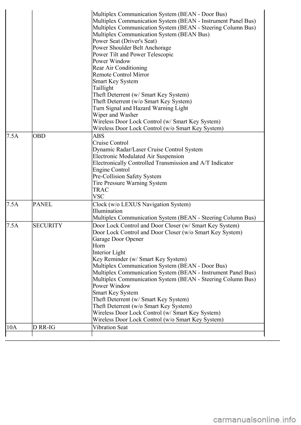
Multiplex Communication System (BEAN - Door Bus)
Multiplex Communication System (BEAN - Instrument Panel Bus)
Multiplex Communication System (BEAN - Steering Column Bus)
Multiplex Communication System (BEAN Bus)
Power Seat (Driver's Seat)
Power Shoulder Belt Anchorage
Power Tilt and Power Telescopic
Power Window
Rear Air Conditioning
Remote Control Mirror
Smart Key System
Taillight
Theft Deterrent (w/ Smart Key System)
Theft Deterrent (w/o Smart Key System)
Turn Signal and Hazard Warning Light
Wiper and Washer
Wireless Door Lock Control (w/ Smart Key System)
Wireless Door Lock Control (w/o Smart Key System)
7.5AOBDABS
Cruise Control
Dynamic Radar/Laser Cruise Control System
Electronic Modulated Air Suspension
Electronically Controlled Transmission and A/T Indicator
Engine Control
Pre-Collision Safety System
Tire Pressure Warning System
TRAC
VSC
7.5APANELClock (w/o LEXUS Navigation System)
Illumination
Multiplex Communication System (BEAN - Steering Column Bus)
7.5ASECURITYDoor Lock Control and Door Closer (w/ Smart Key System)
Door Lock Control and Door Closer (w/o Smart Key System)
Garage Door Opener
Horn
Interior Light
Key Reminder (w/ Smart Key System)
Multiplex Communication System (BEAN - Door Bus)
Multiplex Communication System (BEAN - Instrument Panel Bus)
Multiplex Communication System (BEAN - Steering Column Bus)
Power Window
Smart Key System
Theft Deterrent (w/ Smart Key System)
Theft Deterrent (w/o Smart Key System)
Wireless Door Lock Control (w/ Smart Key System)
Wireless Door Lock Control (w/o Smart Key System)
10AD RR-IGVibration Seat