replacement LEXUS LS430 2003 Factory Repair Manual
[x] Cancel search | Manufacturer: LEXUS, Model Year: 2003, Model line: LS430, Model: LEXUS LS430 2003Pages: 4500, PDF Size: 87.45 MB
Page 1 of 4500
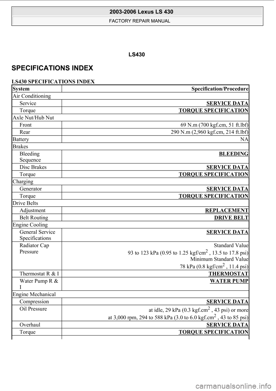
LS430 SPECIFICATIONS INDEX
SystemSpecification/Procedure
Air Conditioning
ServiceSERVICE DATA
TorqueTORQUE SPECIFICATION
Axle Nut/Hub Nut
Front69 N.m (700 kgf.cm, 51 ft.lbf)
Rear290 N.m (2,960 kgf.cm, 214 ft.lbf)
BatteryNA
Brakes
Bleeding
SequenceBLEEDING
Disc BrakesSERVICE DATA
TorqueTORQUE SPECIFICATION
Charging
GeneratorSERVICE DATA
TorqueTORQUE SPECIFICATION
Drive Belts
AdjustmentREPLACEMENT
Belt RoutingDRIVE BELT
Engine Cooling
General Service
SpecificationsSERVICE DATA
Radiator Cap
PressureStandard Value
93 to 123 kPa (0.95 to 1.25 kgf/cm
2 , 13.5 to 17.8 psi)
Minimum Standard Value
78 kPa (0.8 kgf/cm
2 , 11.4 psi)
Thermostat R & ITHERMOSTAT
Water Pump R &
IWATER PUMP
Engine Mechanical
CompressionSERVICE DATA
Oil Pressureat idle, 29 kPa (0.3 kgf.cm2 , 43 psi) or more
at 3,000 rpm, 294 to 588 kPa (3.0 to 6.0 kgf.cm
2 , 43 to 85 psi)
OverhaulSERVICE DATA
TorqueTORQUE SPECIFICATION
Page 65 of 4500
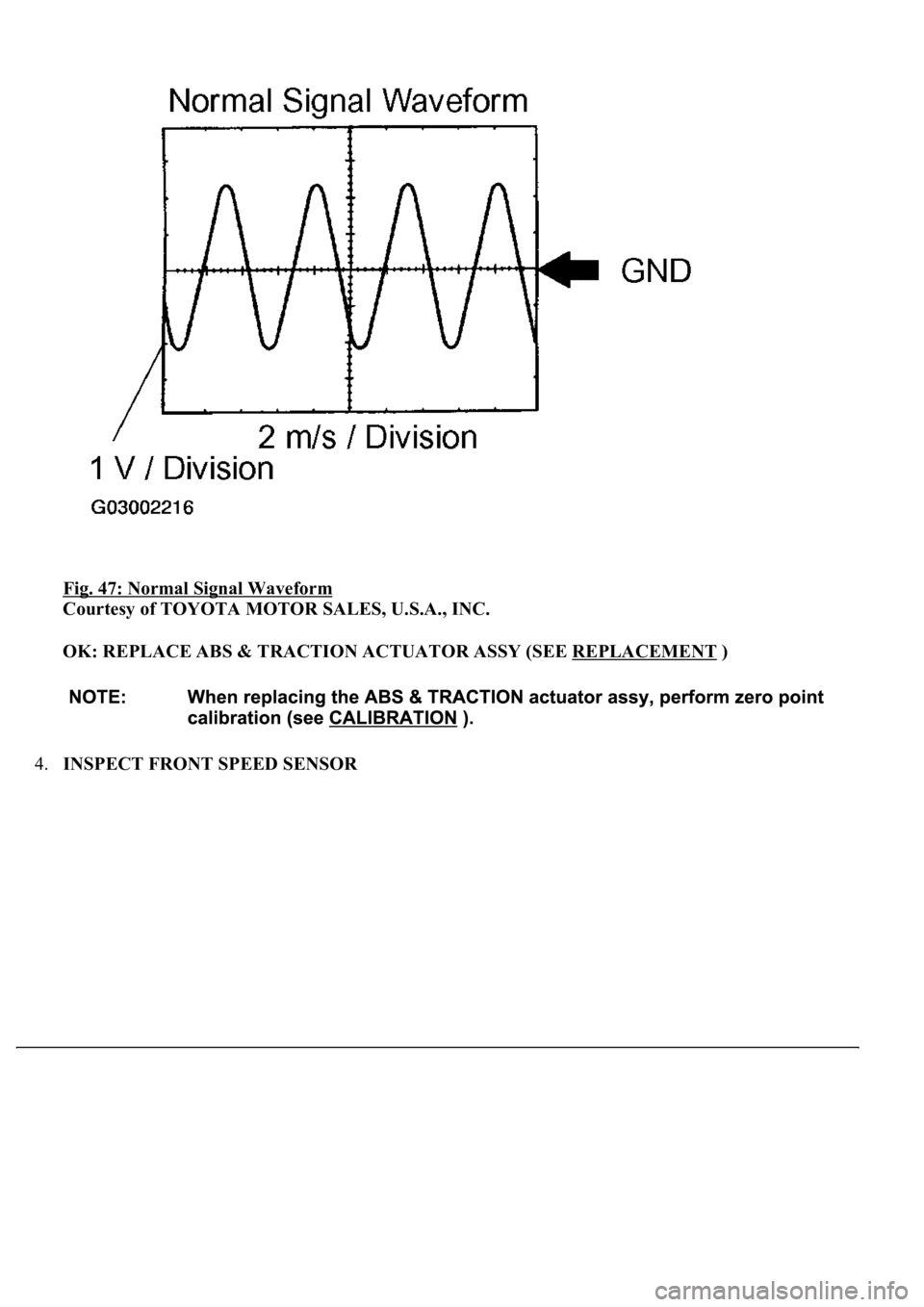
Fig. 47: Normal Signal Waveform
Courtesy of TOYOTA MOTOR SALES, U.S.A., INC.
OK: REPLACE ABS & TRACTION ACTUATOR ASSY (SEE REPLACEMENT
)
4.INSPECT FRONT SPEED SENSOR
Page 68 of 4500
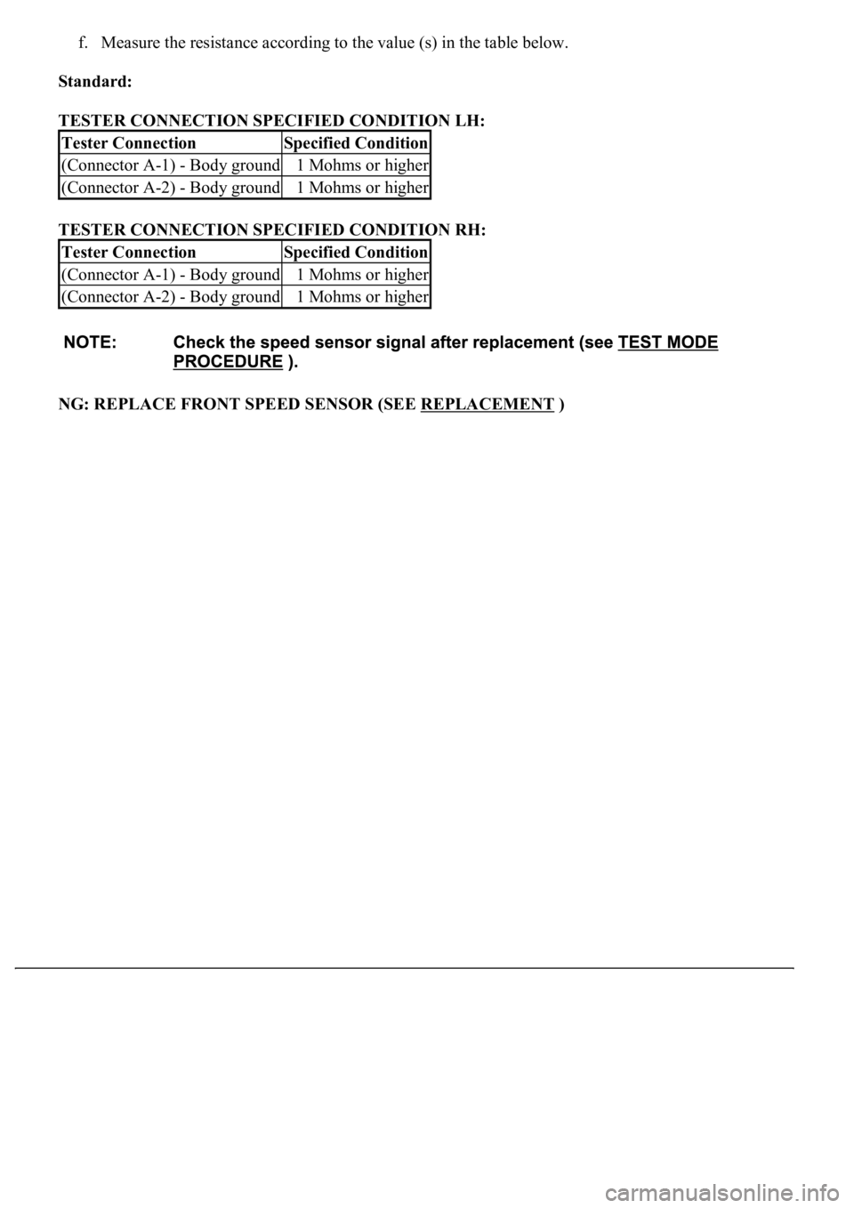
f. Measure the resistance according to the value (s) in the table below.
Standard:
TESTER CONNECTION SPECIFIED CONDITION LH:
TESTER CONNECTION SPECIFIED CONDITION RH:
NG: REPLACE FRONT SPEED SENSOR (SEE REPLACEMENT
)
Tester ConnectionSpecified Condition
(Connector A-1) - Body ground1 Mohms or higher
(Connector A-2) - Body ground1 Mohms or higher
Tester ConnectionSpecified Condition
(Connector A-1) - Body ground1 Mohms or higher
(Connector A-2) - Body ground1 Mohms or higher
Page 72 of 4500
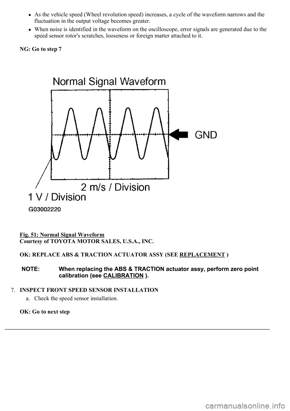
As the vehicle speed (Wheel revolution speed) increases, a cycle of the waveform narrows and the
fluctuation in the output voltage becomes greater.
When noise is identified in the waveform on the oscilloscope, error signals are generated due to the
speed sensor rotor's scratches, looseness or foreign matter attached to it.
NG: Go to step 7
Fig. 51: Normal Signal Waveform
Courtesy of TOYOTA MOTOR SALES, U.S.A., INC.
OK: REPLACE ABS & TRACTION ACTUATOR ASSY (SEE REPLACEMENT
)
7.INSPECT FRONT SPEED SENSOR INSTALLATION
a. Check the speed sensor installation.
OK: Go to next step
Page 73 of 4500
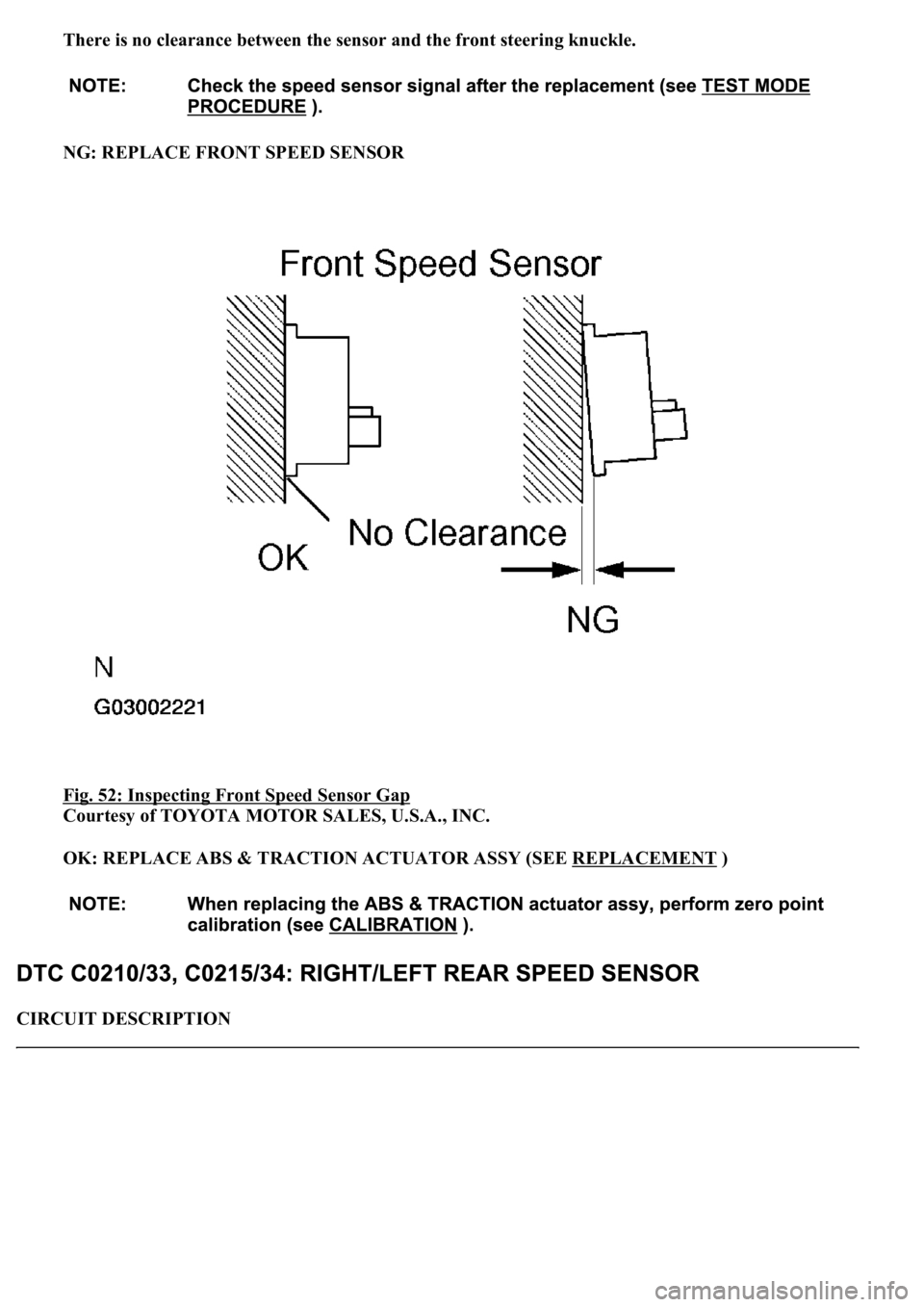
There is no clearance between the sensor and the front steering knuckle.
NG: REPLACE FRONT SPEED SENSOR
Fig. 52: Inspecting Front Speed Sensor Gap
Courtesy of TOYOTA MOTOR SALES, U.S.A., INC.
OK: REPLACE ABS & TRACTION ACTUATOR ASSY (SEE REPLACEMENT
)
CIRCUIT DESCRIPTION
Page 77 of 4500
fluctuation in the output voltage becomes greater.
When noise is identified in the waveform on the oscilloscope, error signals are generated due to the
speed sensor rotor's scratches, looseness or foreign matter attached to it.
NG: Go to step 7
OK: REPLACE ABS & TRACTION ACTUATOR ASSY (SEE REPLACEMENT
)
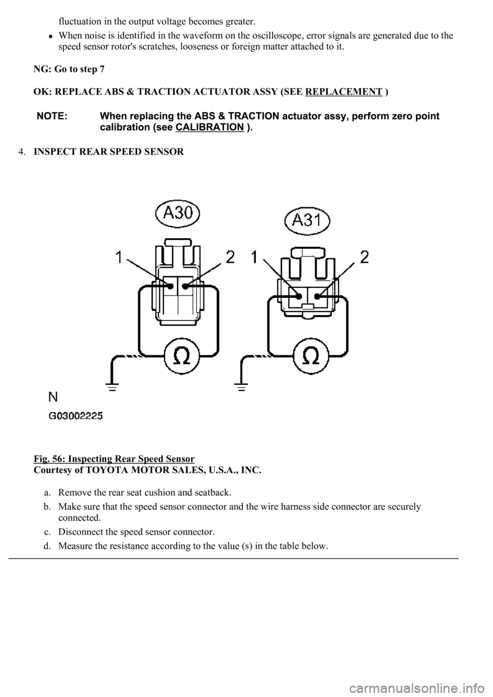
4.INSPECT REAR SPEED SENSOR
Fig. 56: Inspecting Rear Speed Sensor
Courtesy of TOYOTA MOTOR SALES, U.S.A., INC.
a. Remove the rear seat cushion and seatback.
b. Make sure that the speed sensor connector and the wire harness side connector are securely
connected.
c. Disconnect the speed sensor connector.
d. Measure the resistance accordin
g to the value (s) in the table below.
Page 78 of 4500
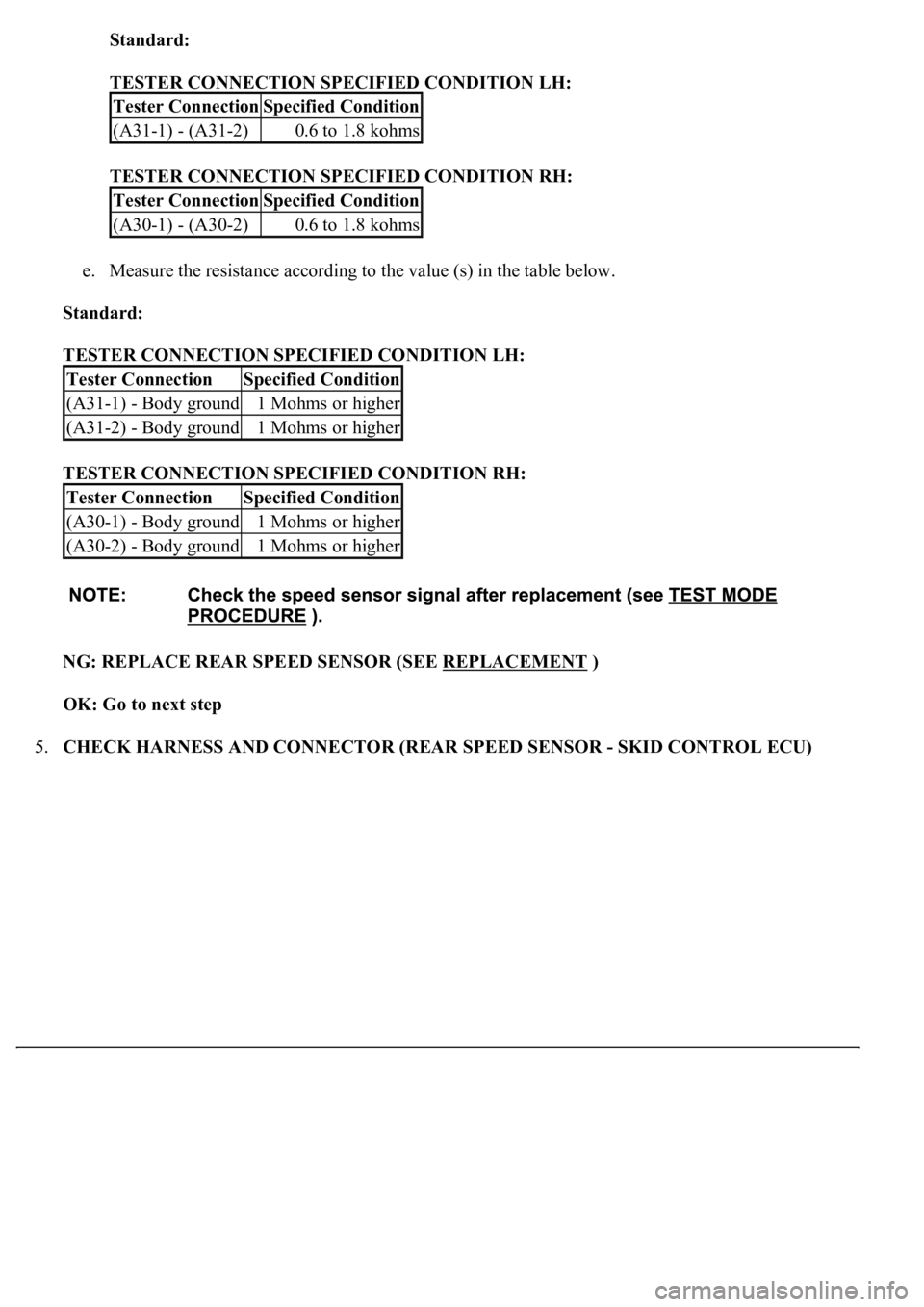
Standard:
TESTER CONNECTION SPECIFIED CONDITION LH:
TESTER CONNECTION SPECIFIED CONDITION RH:
e. Measure the resistance according to the value (s) in the table below.
Standard:
TESTER CONNECTION SPECIFIED CONDITION LH:
TESTER CONNECTION SPECIFIED CONDITION RH:
NG: REPLACE REAR SPEED SENSOR (SEE REPLACEMENT
)
OK: Go to next step
5.CHECK HARNESS AND CONNECTOR (REAR SPEED SENSOR - SKID CONTROL ECU)
Tester ConnectionSpecified Condition
(A31-1) - (A31-2)0.6 to 1.8 kohms
Tester ConnectionSpecified Condition
(A30-1) - (A30-2)0.6 to 1.8 kohms
Tester ConnectionSpecified Condition
(A31-1) - Body ground1 Mohms or higher
(A31-2) - Body ground1 Mohms or higher
Tester ConnectionSpecified Condition
(A30-1) - Body ground1 Mohms or higher
(A30-2) - Body ground1 Mohms or higher
Page 82 of 4500
OK: REPLACE ABS & TRACTION ACTUATOR ASSY (SEE REPLACEMENT )
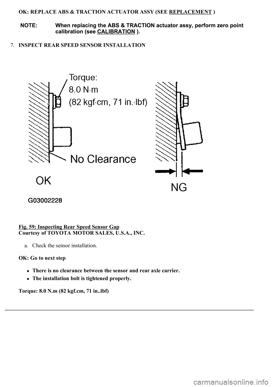
7.INSPECT REAR SPEED SENSOR INSTALLATION
Fig. 59: Inspecting Rear Speed Sensor Gap
Courtesy of TOYOTA MOTOR SALES, U.S.A., INC.
a. Check the sensor installation.
OK: Go to next step
There is no clearance between the sensor and rear axle carrier.
The installation bolt is tightened properly.
Torque: 8.0 N.m (82 kgf.cm, 71 in..lbf)
Page 83 of 4500
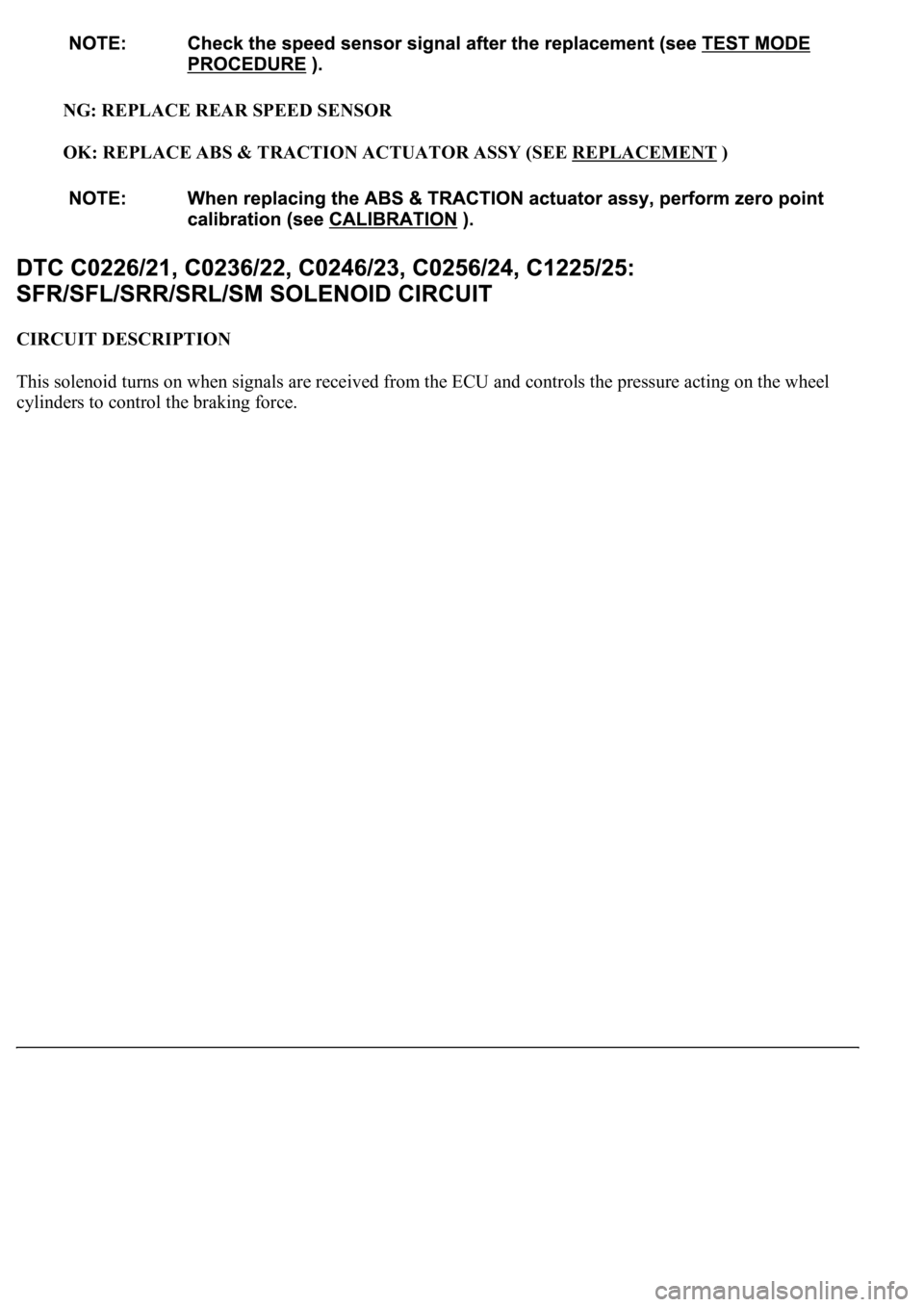
NG: REPLACE REAR SPEED SENSOR
OK: REPLACE ABS & TRACTION ACTUATOR ASSY (SEE REPLACEMENT
)
CIRCUIT DESCRIPTION
<0037004b004c0056000300560052004f004800510052004c00470003005700580055005100560003005200510003005a004b0048005100030056004c004a00510044004f0056000300440055004800030055004800460048004c0059004800470003004900
550052005000030057004b0048000300280026003800030044[nd controls the pressure acting on the wheel
c
ylinders to control the braking force.
Page 86 of 4500
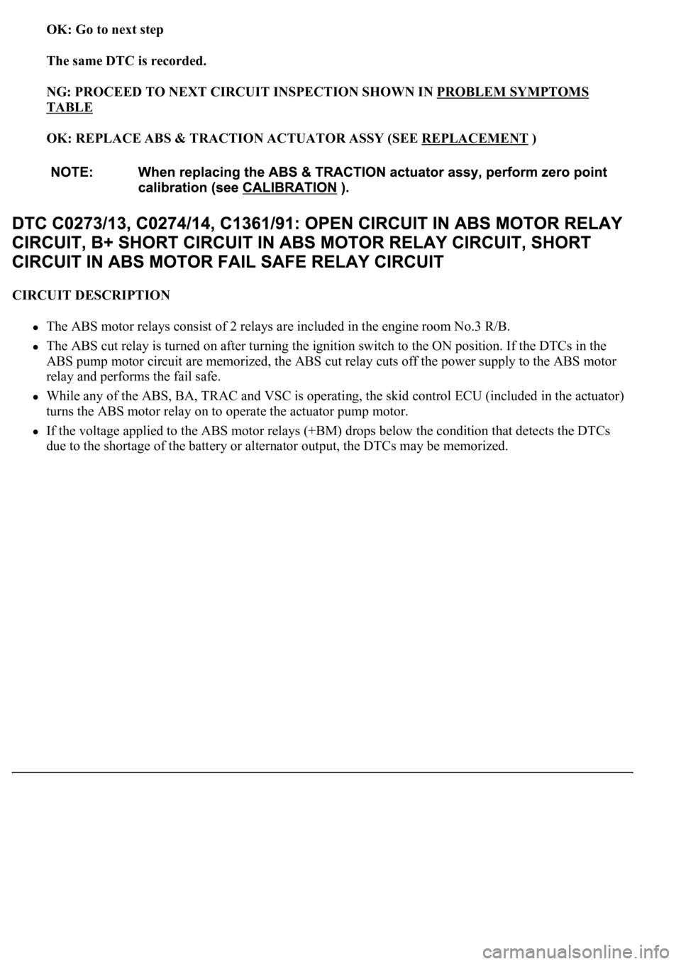
OK: Go to next step
The same DTC is recorded.
NG: PROCEED TO NEXT CIRCUIT INSPECTION SHOWN IN PROBLEM SYMPTOMS
TABLE
OK: REPLACE ABS & TRACTION ACTUATOR ASSY (SEE REPLACEMENT
)
CIRCUIT DESCRIPTION
The ABS motor relays consist of 2 relays are included in the engine room No.3 R/B.
The ABS cut relay is turned on after turning the ignition switch to the ON position. If the DTCs in the
ABS pump motor circuit are memorized, the ABS cut relay cuts off the power supply to the ABS motor
relay and performs the fail safe.
While any of the ABS, BA, TRAC and VSC is operating, the skid control ECU (included in the actuator)
<0057005800550051005600030057004b00480003002400250036000300500052005700520055000300550048004f0044005c0003005200510003005700520003005200530048005500440057004800030057004b0048000300440046005700580044005700
52005500030053005800500053000300500052005700520055[.
If the voltage applied to the ABS motor relays (+BM) drops below the condition that detects the DTCs
due to the shorta
ge of the battery or alternator output, the DTCs may be memorized.