LEXUS RX350 2015 Owners Manual
RX350 2015
LEXUS
LEXUS
https://www.carmanualsonline.info/img/36/58970/w960_58970-0.png
LEXUS RX350 2015 Owners Manual
Trending: alarm, torque, warning lights, radio antenna, key battery, maintenance reset, engine oil capacity
Page 701 of 886
7014-3. Do-it-yourself maintenance
4
Maintenance and care Electronic key battery Replace the battery with a new one if it is discharged.
■ You will need the following items:
● Flathead screwdriver
● Small Phillips-head sc rewdriver
● Lithium battery (CR1632)
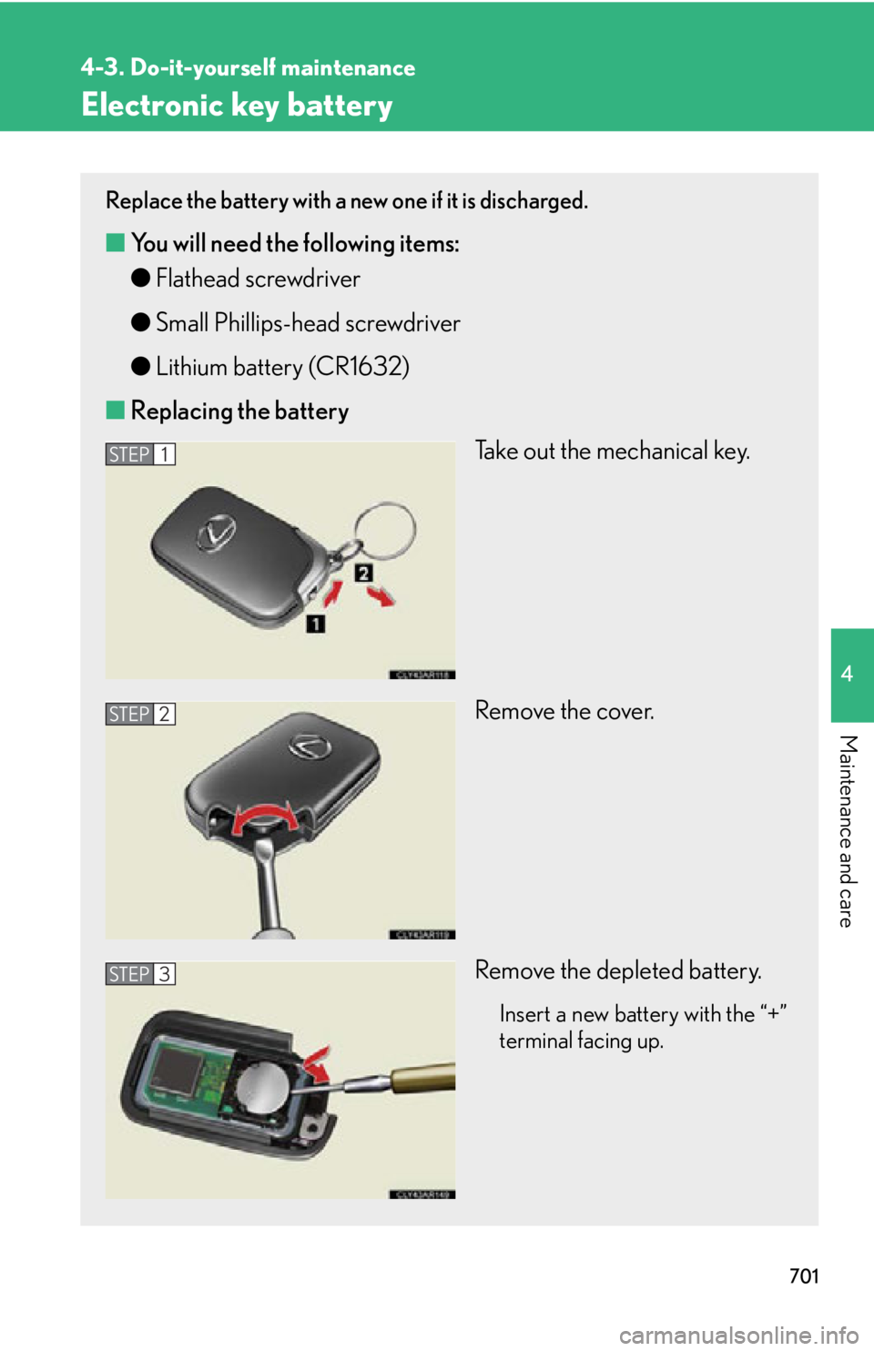
■ Replacing the battery
Take out the mechanical key.
Remove the cover.
Remove the depleted battery.
Insert a new battery with the “+”
terminal facing up.STEP 1
STEP 2
STEP 3
Page 702 of 886
7024-3. Do-it-yourself maintenance
■
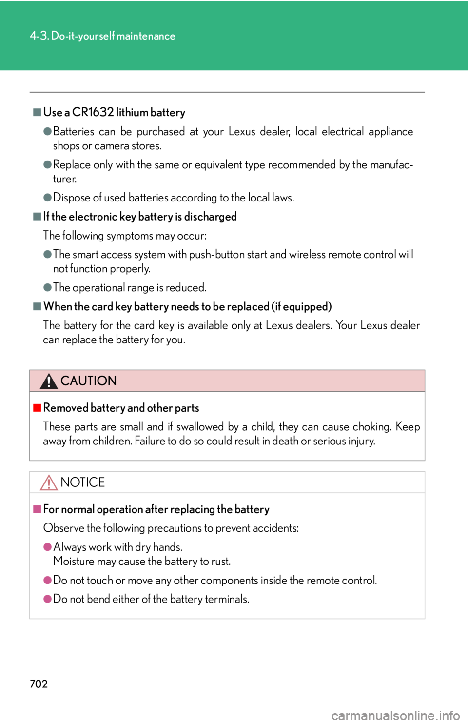
Use a CR1632 lithium battery ●
Batteries can be purchased at your Le xus dealer, local electrical appliance
shops or camera stores.●
Replace only with the same or equivalent type recommended by the manufac-
turer.●
Dispose of used batteries according to the local laws.■
If the electronic key battery is discharged
The following symptoms may occur: ●
The smart access system with push-button start and wireless remote control will
not function properly.●
The operational range is reduced.■
When the card key battery needs to be replaced (if equipped)
The battery for the card key is available only at Lexus dealers. Your Lexus dealer
can replace the battery for you.
CAUTION■
Removed battery and other parts
These parts are small and if swallowed by a child, they can cause choking. Keep
away from children. Failure to do so could result in death or serious injury.
NOTICE■
For normal operation after replacing the battery
Observe the following precautions to prevent accidents:
●
Always work with dry hands.
Moisture may cause the battery to rust.
●
Do not touch or move any other comp onents inside the remote control.
●
Do not bend either of the battery terminals.
Page 703 of 886
7034-3. Do-it-yourself maintenance
4
Maintenance and care Checking and replacing fuses If any of the electrical components do not operate, a fuse may have blown.
If this happens, check and re place the fuses as necessary.
Turn the “ENGINE START STOP” switch off.
After a system failure, see “Fuse layout and amperage ratings”
for details about which fuse to check. ( P. 7 0 6 )
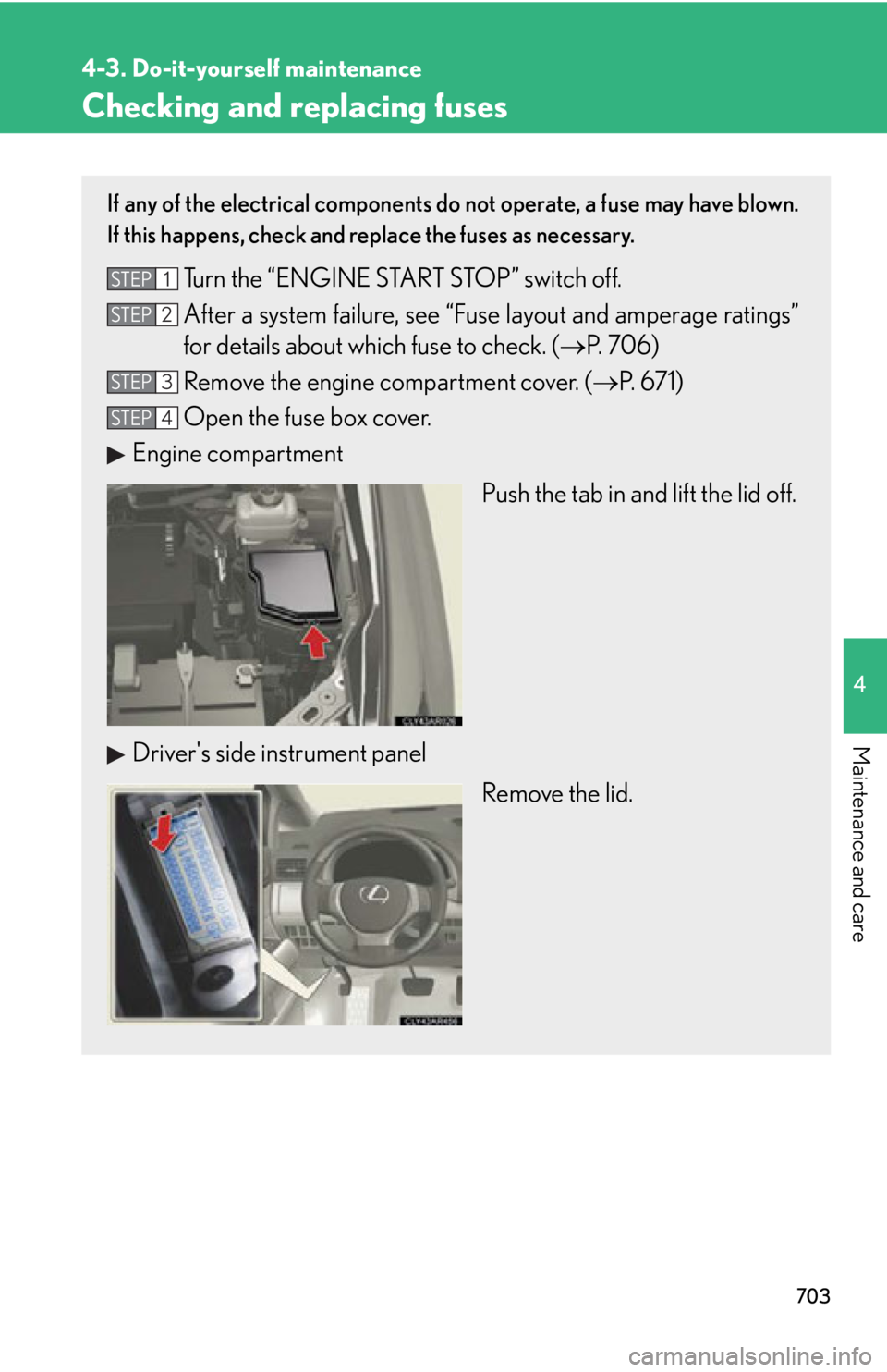
Remove the engine compartment cover. ( P. 671)
Open the fuse box cover.
Engine compartment
Push the tab in and lift the lid off.
Driver's side instrument panel
Remove the lid.STEP 1
STEP 2
STEP 3
STEP 4
Page 704 of 886
7044-3. Do-it-yourself maintenance
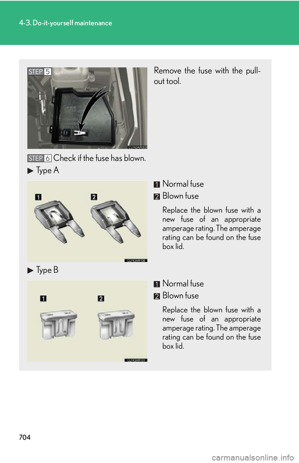
Remove the fuse with the pull-
out tool.
Check if the fuse has blown.
Type A
Normal fuse
Blown fuse Replace the blown fuse with a
new fuse of an appropriate
amperage rating. The amperage
rating can be found on the fuse
box lid.
Type B
Normal fuse
Blown fuse Replace the blown fuse with a
new fuse of an appropriate
amperage rating. The amperage
rating can be found on the fuse
box lid.STEP 5
STEP 6
Page 705 of 886
7054-3. Do-it-yourself maintenance
4
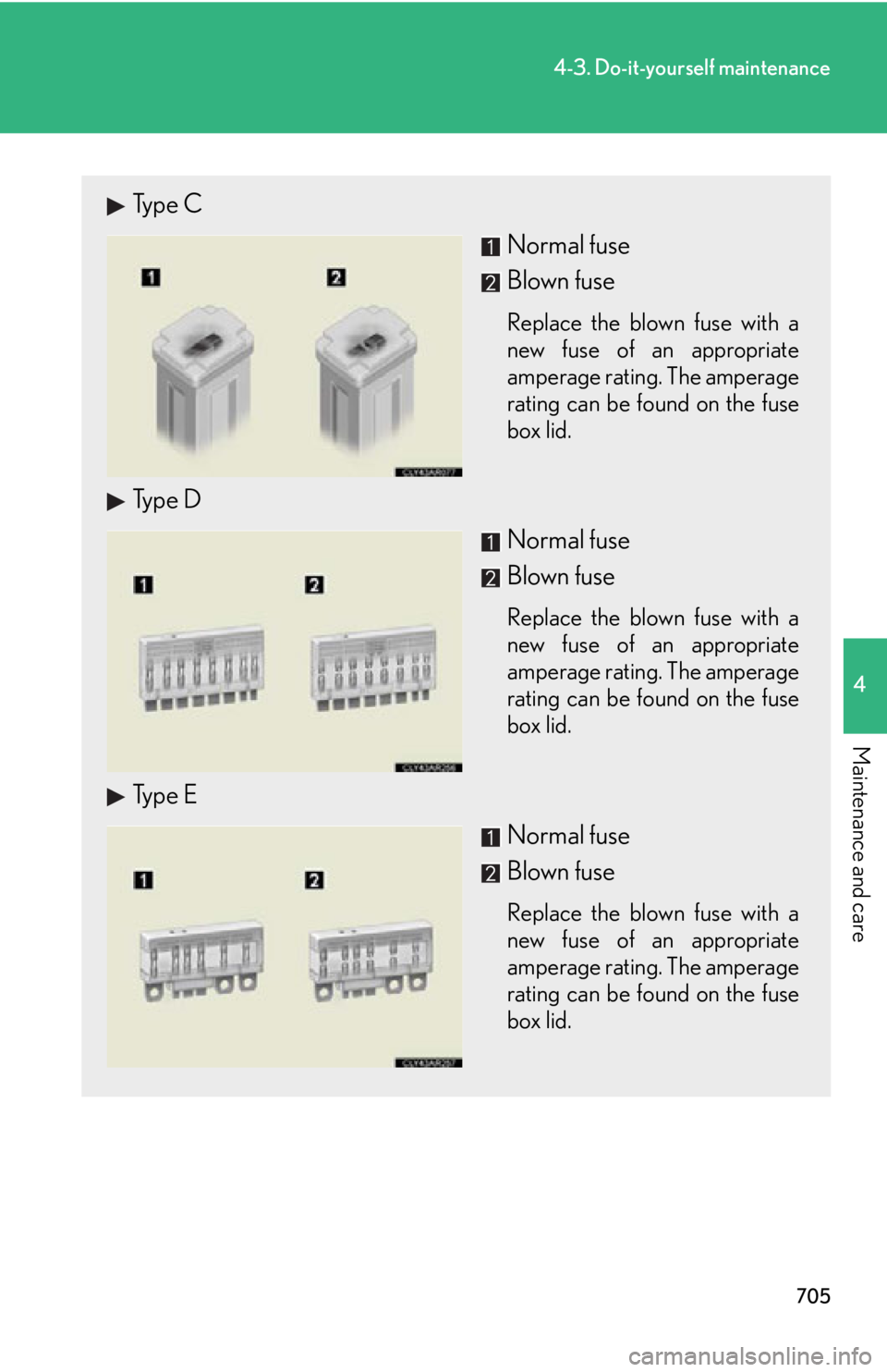
Maintenance and care Type C
Normal fuse
Blown fuse Replace the blown fuse with a
new fuse of an appropriate
amperage rating. The amperage
rating can be found on the fuse
box lid.
Type D
Normal fuse
Blown fuse Replace the blown fuse with a
new fuse of an appropriate
amperage rating. The amperage
rating can be found on the fuse
box lid.
Type E
Normal fuse
Blown fuse Replace the blown fuse with a
new fuse of an appropriate
amperage rating. The amperage
rating can be found on the fuse
box lid.
Page 706 of 886
7064-3. Do-it-yourself maintenance
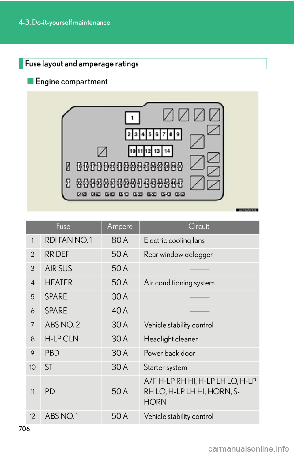
Fuse layout and amperage ratings
■ Engine compartment
Fuse Ampere Circuit1
RDI FAN NO. 1 80 A Electric cooling fans2
RR DEF 50 A Rear window defogger3
AIR SUS 50 A4
HEATER 50 A Air conditioning system5
SPARE 30 A6
SPARE 40 A7
ABS NO. 2 30 A Vehicle stability control8
H-LP CLN 30 A Headlight cleaner9
PBD 30 A Power back door10
ST 30 A Starter system
11
PD 50 A A/F, H-LP RH HI, H-LP LH LO, H-LP
RH LO, H-LP LH HI, HORN, S-
HORN
12
ABS NO. 1 50 A Vehicle stability control
Page 707 of 886
7074-3. Do-it-yourself maintenance
4
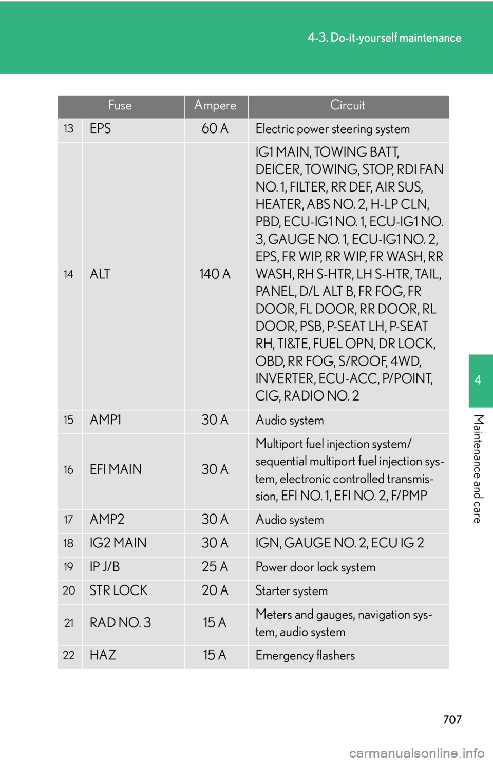
Maintenance and care 13
EPS 60 A Electric power steering system
14
ALT 140 A IG1 MAIN, TOWING BATT,
DEICER, TOWING, STOP, RDI FAN
NO. 1, FILTER, RR DEF, AIR SUS,
HEATER, ABS NO. 2, H-LP CLN,
PBD, ECU-IG1 NO. 1, ECU-IG1 NO.
3, GAUGE NO. 1, ECU-IG1 NO. 2,
EPS, FR WIP, RR WIP, FR WASH, RR
WASH, RH S-HTR, LH S-HTR, TAIL,
PANEL, D/L ALT B, FR FOG, FR
DOOR, FL DOOR, RR DOOR, RL
DOOR, PSB, P-SEAT LH, P-SEAT
RH, TI&TE, FUEL OPN, DR LOCK,
O B D, R R F O G, S / R O O F, 4 W D,
INVERTER, ECU-ACC, P/POINT,
CIG, RADIO NO. 215
AMP1 30 A Audio system16
EFI MAIN 30 A Multiport fuel injection system/
sequential multiport fuel injection sys-
tem, electronic controlled transmis-
sion, EFI NO. 1, EFI NO. 2, F/PMP17
AMP2 30 A Audio system18
IG2 MAIN 30 A IGN, GAUGE NO. 2, ECU IG 219
IP J/B 25 A Power door lock system20
STR LOCK 20 A Starter system
21
RAD NO. 3 15 A Meters and gauges, navigation sys-
tem, audio system
22
HAZ 15 A Emergency flashersFuse Ampere Circuit
Page 708 of 886

7084-3. Do-it-yourself maintenance
23
ETCS 10 A Multiport fuel injection system/
sequential multiport fuel injection sys-
tem24
RAD NO. 1 10 A Audio system, navigation system25
AM2 7. 5 A Starter system26
ECU-B NO. 2 7. 5 A Air conditioning system, front passen-
ger occupant classification system,
audio system, vehicle stability control
system, power windows27
MAYDAY/TEL 7. 5 A MAYDAY/TEL28
IMMOBI 7. 5 A IMMOBI29
ALT-S 7. 5 A Charging system30
DRL 7. 5 A Daytime running light system31
IGN 10 A Multiport fuel injection system/
sequential multiport fuel injection sys-
tem32
DOME 10 A Vanity mirror lights, luggage compart-
ment lights, interior lights, personal
lights, door courtesy lights, footwell
lights, scuff lights
33
ECU-B NO. 1 10 A Tilt and telescopic steering, multiplex
communication system, meters and
gauges, driving position memory,
power seats, power back door, head-
up display, starter system, outside rear
view mirror, steering sensor, garage
door openerFuse Ampere Circuit
Page 709 of 886
7094-3. Do-it-yourself maintenance
4
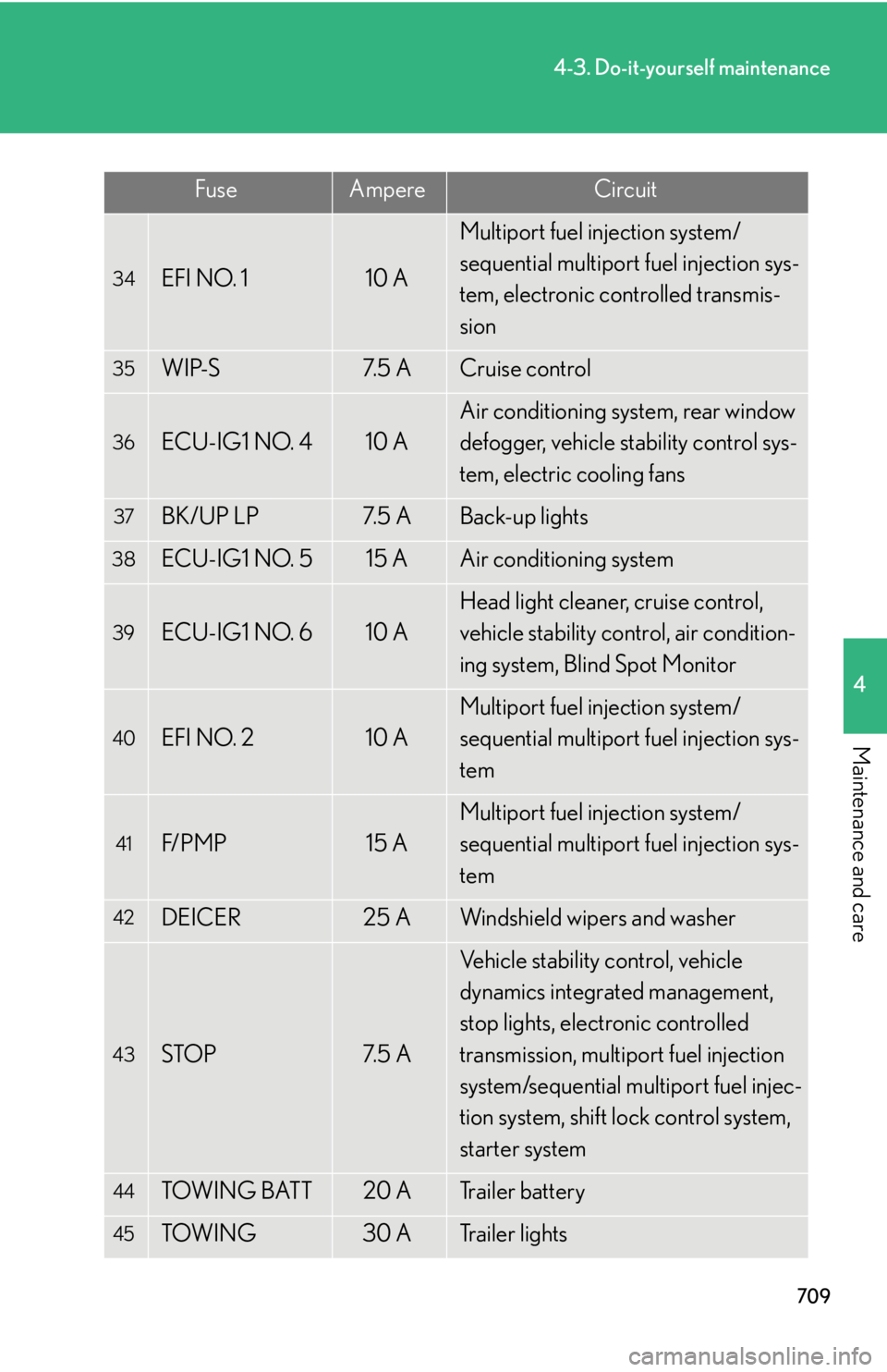
Maintenance and care 34
EFI NO. 1 10 A Multiport fuel injection system/
sequential multiport fuel injection sys-
tem, electronic controlled transmis-
sion35
WIP-S 7. 5 A Cruise control36
ECU-IG1 NO. 4 10 A Air conditioning system, rear window
defogger, vehicle stability control sys-
tem, electric cooling fans37
BK/UP LP 7. 5 A Back-up lights38
ECU-IG1 NO. 5 15 A Air conditioning system39
ECU-IG1 NO. 6 10 A Head light cleaner, cruise control,
vehicle stability control, air condition-
ing system, Blind Spot Monitor40
EFI NO. 2 10 A Multiport fuel injection system/
sequential multiport fuel injection sys-
tem41
F/ P M P 15 A Multiport fuel injection system/
sequential multiport fuel injection sys-
tem42
DEICER 25 A Windshield wipers and washer
43
STOP 7. 5 A Vehicle stability control, vehicle
dynamics integrated management,
stop lights, electronic controlled
transmission, multiport fuel injection
system/sequential multiport fuel injec-
tion system, shift lock control system,
starter system
44
TOW I N G BAT T 20 A Trailer battery
45
TOW I N G 30 A Trailer lightsFuse Ampere Circuit
Page 710 of 886
7104-3. Do-it-yourself maintenance
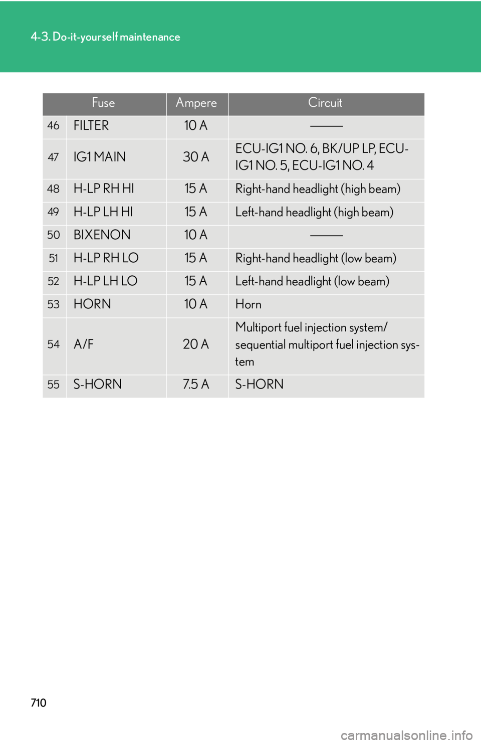
46
FILTER 10 A47
IG1 MAIN 30 A ECU-IG1 NO. 6, BK/UP LP, ECU-
IG1 NO. 5, ECU-IG1 NO. 448
H-LP RH HI 15 A Right-hand headlight (high beam)49
H-LP LH HI 15 A Left-hand headlight (high beam)50
BIXENON 10 A51
H-LP RH LO 15 A Right-hand headlight (low beam)52
H-LP LH LO 15 A Left-hand headlight (low beam)53
HORN 10 A Horn54
A/F 20 A Multiport fuel injection system/
sequential multiport fuel injection sys-
tem55
S-HORN 7. 5 A S-HORNFuse Ampere Circuit
Trending: fuel cap, check transmission fluid, weight, wheelbase, center console, tire size, wheel size
