LEXUS SC400 1991 Service Repair Manual
Manufacturer: LEXUS, Model Year: 1991,
Model line: SC400,
Model: LEXUS SC400 1991
Pages: 4087, PDF Size: 75.75 MB
LEXUS SC400 1991 Service Repair Manual
SC400 1991
LEXUS
LEXUS
https://www.carmanualsonline.info/img/36/57051/w960_57051-0.png
LEXUS SC400 1991 Service Repair Manual
Trending: Throttle Position sensor, traction control, instrument panel, charging, change wheel, automatic transmission, fuel pump
Page 1931 of 4087
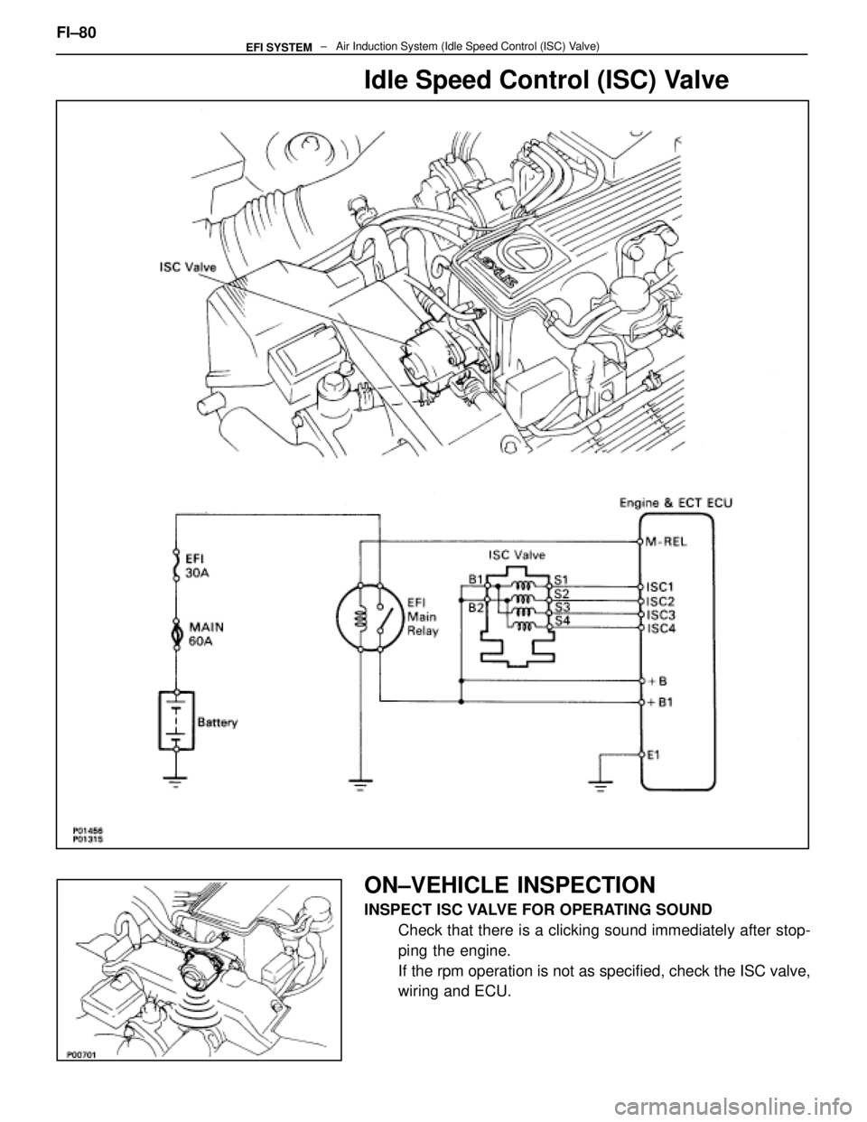
Idle Speed Control (ISC) Valve
ON±VEHICLE INSPECTION
INSPECT ISC VALVE FOR OPERATING SOUNDCheck that there is a clicking sound immediately after stop-
ping the engine.
If the rpm operation is not as specified, check the ISC valve,
wiring and ECU.
FI±80
± Air Induction System (Idle Speed Control (ISC\
) Valve)EFI SYSTEM
WhereEverybodyKnowsYourName
Page 1932 of 4087
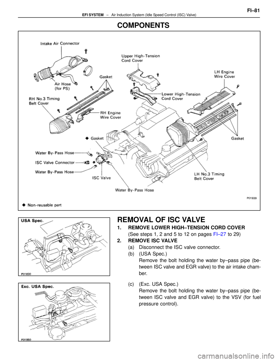
COMPONENTS
REMOVAL OF ISC VALVE
1. REMOVE LOWER HIGH±TENSION CORD COVER(See steps 1, 2 and 5 to 12 on pages FI±27 to 29)
2. REMOVE ISC VALVE
(a) Disconnect the ISC valve connector.
(b) (USA Spec.)Remove the bolt holding the water by±pass pipe (be-
tween ISC valve and EGR valve) to the air intake cham-
ber.
(c) (Exc. USA Spec.) Remove the bolt holding the water by±pass pipe (be-
tween ISC valve and EGR valve) to the VSV (for fuel
pressure control). FI±81
EFI SYSTEM
± Air Induction System (Idle Speed Control (ISC) Valve)
WhereEverybodyKnowsYourName
Page 1933 of 4087
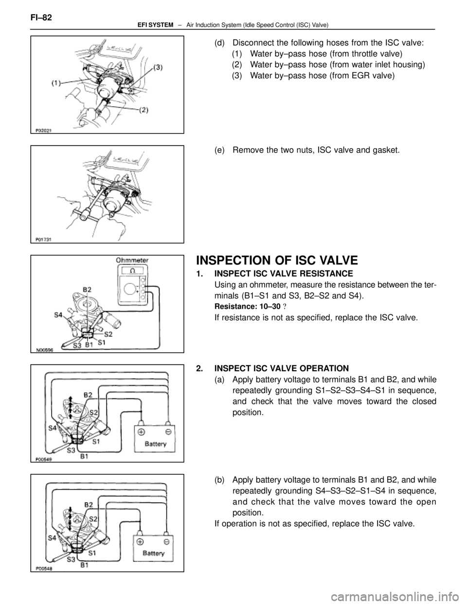
(d) Disconnect the following hoses from the ISC valve:(1) Water by±pass hose (from throttle valve)
(2) Water by±pass hose (from water inlet housing)
(3) Water by±pass hose (from EGR valve)
(e) Remove the two nuts, ISC valve and gasket.
INSPECTION OF ISC VALVE
1. INSPECT ISC VALVE RESISTANCE Using an ohmmeter, measure the resistance between the ter-
minals (B1±S1 and S3, B2±S2 and S4).
Resistance: 10±30 �
If resistance is not as specified, replace the ISC valve.
2. INSPECT ISC VALVE OPERATION (a) Apply battery voltage to terminals B1 and B2, and whilerepeatedly grounding S1±S2±S3±S4±S1 in sequence,
and check that the valve moves toward the closed
position.
(b) Apply battery voltage to terminals B1 and B2, and while repeatedly grounding S4±S3±S2±S1±S4 in sequence,
and check that the valve moves toward the open
position.
If operation is not as specified, replace the ISC valve.
FI±82
EFI SYSTEM
± Air Induction System (Idle Speed Control (ISC) Valve)
WhereEverybodyKnowsYourName
Page 1934 of 4087
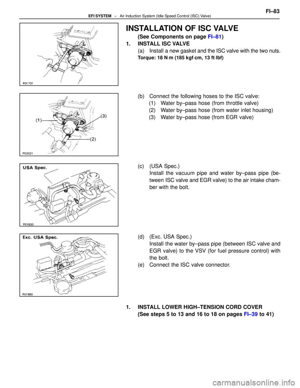
INSTALLATION OF ISC VALVE
(See Components on page FI±81)
1. INSTALL ISC VALVE (a) Install a new gasket and the ISC valve with the two nuts.
Torque: 18 N Vm (185 kgf Vcm, 13 ft Vlbf)
(b) Connect the following hoses to the ISC valve:
(1) Water by±pass hose (from throttle valve)
(2) Water by±pass hose (from water inlet housing)
(3) Water by±pass hose (from EGR valve)
(c) (USA Spec.) Install the vacuum pipe and water by±pass pipe (be-
tween ISC valve and EGR valve) to the air intake cham-
ber with the bolt.
(d) (Exc. USA Spec.) Install the water by±pass pipe (between ISC valve and
EGR valve) to the VSV (for fuel pressure control) with
the bolt.
(e) Connect the ISC valve connector.
1. INSTALL LOWER HIGH±TENSION CORD COVER (See steps 5 to 13 and 16 to 18 on pages FI±39 to 41)FI±83
EFI SYSTEM
± Air Induction System (Idle Speed Control (ISC) Valve)
WhereEverybodyKnowsYourName
Page 1935 of 4087
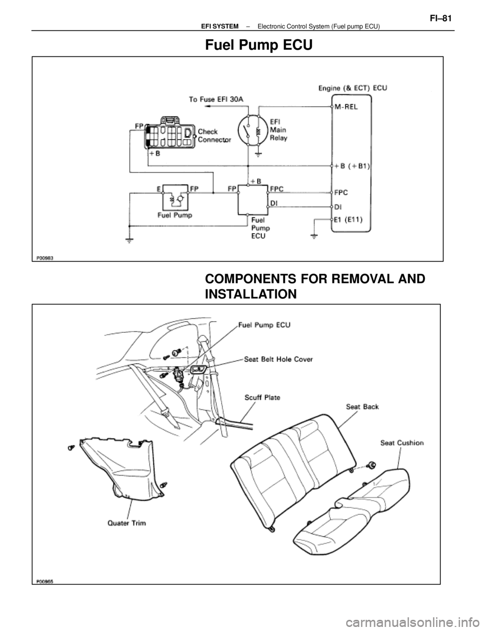
Fuel Pump ECU
COMPONENTS FOR REMOVAL AND
INSTALLATION
±
EFI SYSTEM Electronic Control System (Fuel pump ECU)FI±81
WhereEverybodyKnowsYourName
Page 1936 of 4087
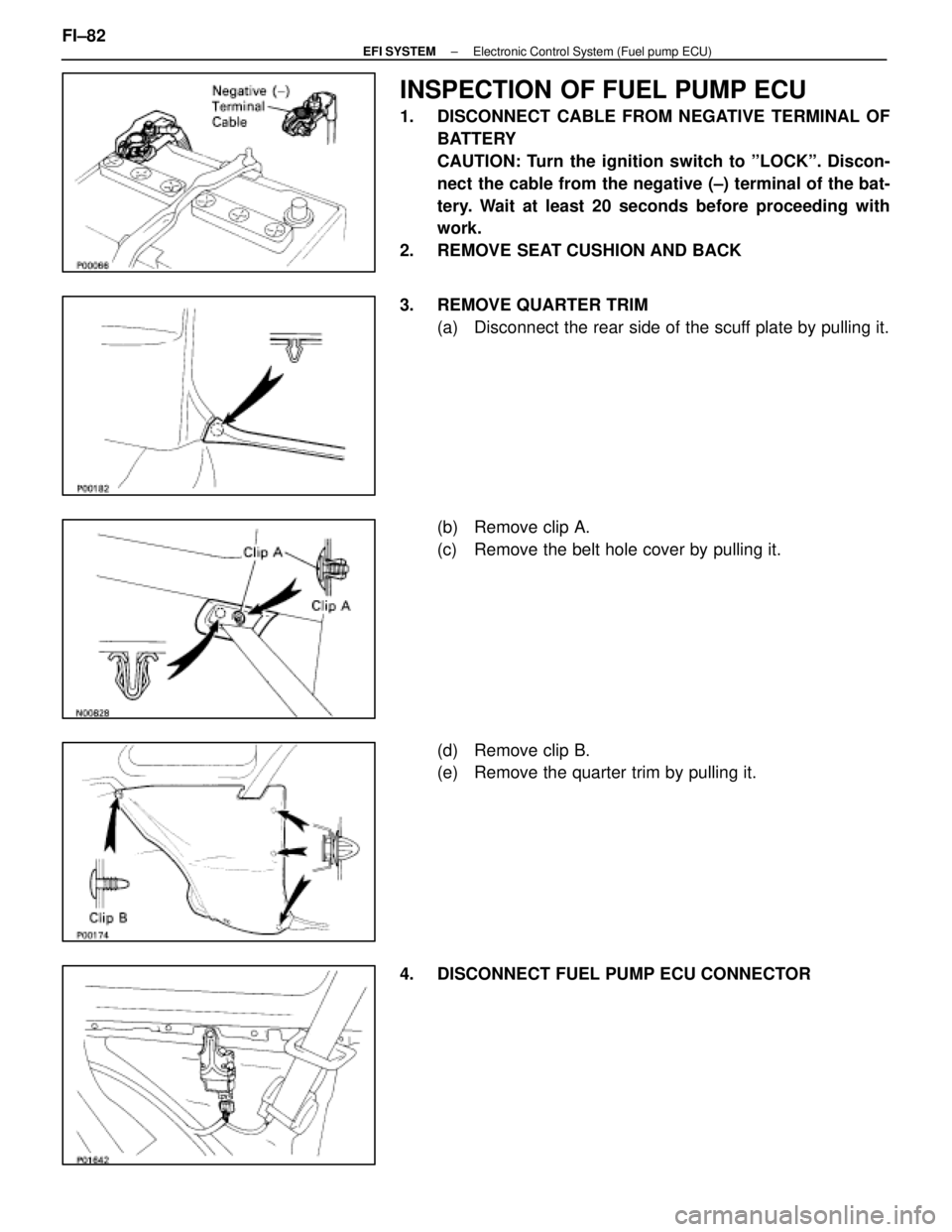
INSPECTION OF FUEL PUMP ECU
1. DISCONNECT CABLE FROM NEGATIVE TERMINAL OFBATTERY
CAUTION: Turn the ignition switch to ºLOCKº. Discon-
nect the cable from the negative (±) terminal of the bat-
tery. Wait at least 20 seconds before proceeding with
work.
2. REMOVE SEAT CUSHION AND BACK
3. REMOVE QUARTER TRIM (a) Disconnect the rear side of the scuff plate by pulling it.
(b) Remove clip A.
(c) Remove the belt hole cover by pulling it.
(d) Remove clip B.
(e) Remove the quarter trim by pulling it.
4. DISCONNECT FUEL PUMP ECU CONNECTOR
FI±82
±
EFI SYSTEM Electronic Control System (Fuel pump ECU)
WhereEverybodyKnowsYourName
Page 1937 of 4087
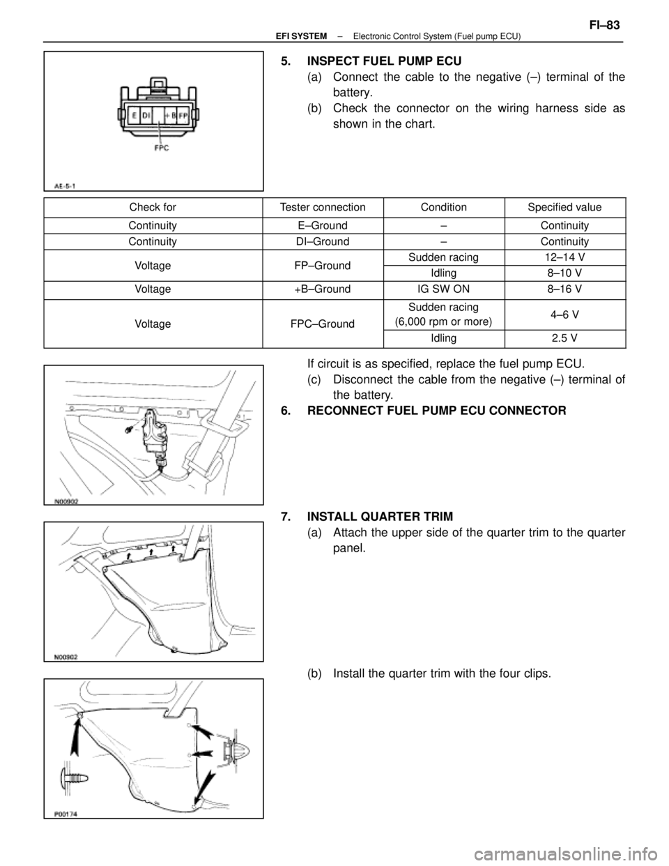
5. INSPECT FUEL PUMP ECU(a) Connect the cable to the negative (±) terminal of thebattery.
(b) Check the connector on the wiring harness side as shown in the chart.
Check forTester connectionConditionSpecified value
ContinuityE±Ground±Continuity
ContinuityDI±Ground±Continuity
VoltageFP GroundSudden racing12±14 VVoltageFP±GroundIdling8±10 V
Voltage+B±GroundIG SW ON8±16 V
VoltageFPC±Ground
Sudden racing
(6,000 rpm or more)4±6 VVoltageFPC Ground
Idling2.5 V
If circuit is as specified, replace the fuel pump ECU.
(c) Disconnect the cable from the negative (±) terminal of the battery.
6. RECONNECT FUEL PUMP ECU CONNECTOR
7. INSTALL QUARTER TRIM (a) Attach the upper side of the quarter trim to the quarterpanel.
(b) Install the quarter trim with the four clips.
±
EFI SYSTEM Electronic Control System (Fuel pump ECU)FI±83
WhereEverybodyKnowsYourName
Page 1938 of 4087
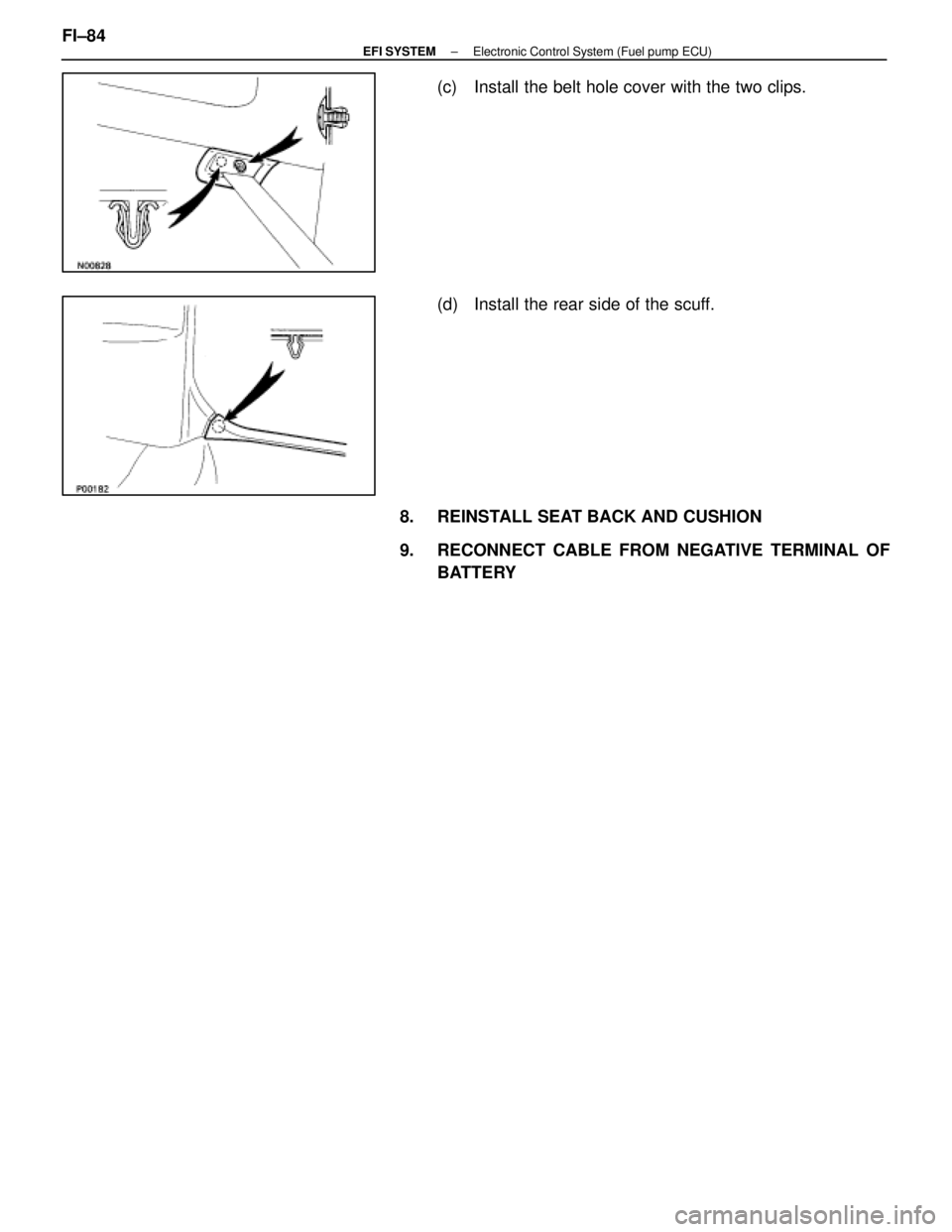
(c) Install the belt hole cover with the two clips.
(d) Install the rear side of the scuff.
8. REINSTALL SEAT BACK AND CUSHION
9. RECONNECT CABLE FROM NEGATIVE TERMINAL OF BATTERY
FI±84
±
EFI SYSTEM Electronic Control System (Fuel pump ECU)
WhereEverybodyKnowsYourName
Page 1939 of 4087
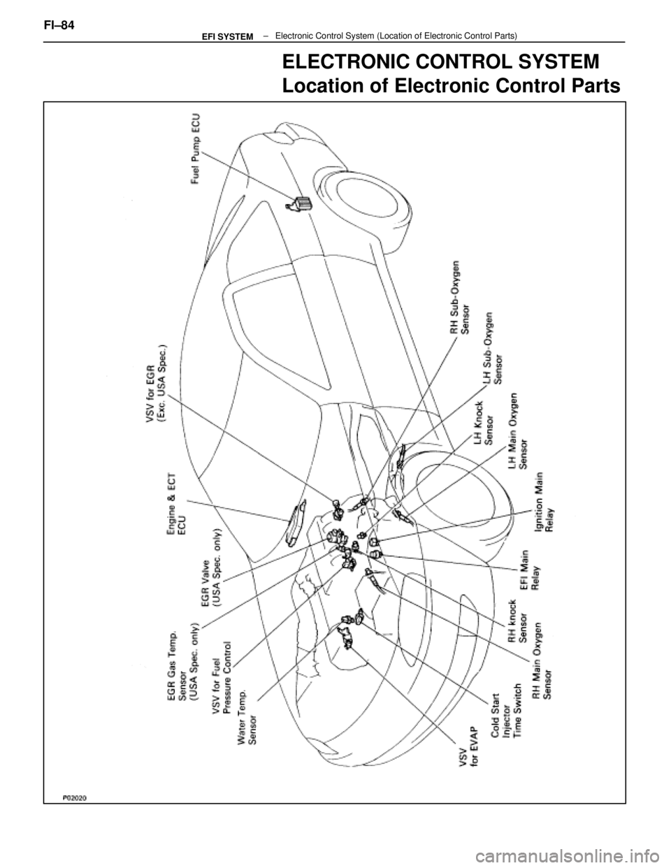
ELECTRONIC CONTROL SYSTEM
Location of Electronic Control Parts
FI±84 ± Electronic Control\
System (Location of Electronic Control Parts)EFI SYSTEM
WhereEverybodyKnowsYourName
Page 1940 of 4087
EFI Main Relay
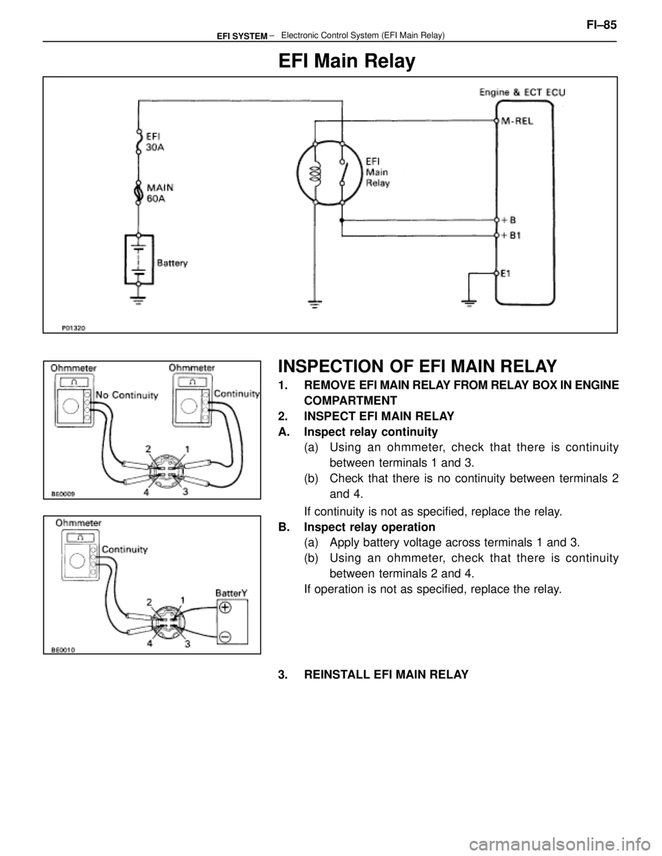
INSPECTION OF EFI MAIN RELAY
1. REMOVE EFI MAIN RELAY FROM RELAY BOX IN ENGINE
COMPARTMENT
2. INSPECT EFI MAIN RELAY
A. Inspect relay continuity (a) Using an ohmmeter, check that there is continuity
between terminals 1 and 3.
(b) Check that there is no continuity between terminals 2 and 4.
If continuity is not as specified, replace the relay.
B. Inspect relay operation (a) Apply battery voltage across terminals 1 and 3.
(b) Using an ohmmeter, check that there is continuity
between terminals 2 and 4.
If operation is not as specified, replace the relay.
3. REINSTALL EFI MAIN RELAY FI±85
± Electronic Control System (EFI Main Relay\
)EFI SYSTEM
WhereEverybodyKnowsYourName
Trending: open gas tank, high beam, coolant reservoir, mirror controls, tires, radio, wheel torque
