LEXUS SC400 1991 Service Repair Manual
Manufacturer: LEXUS, Model Year: 1991,
Model line: SC400,
Model: LEXUS SC400 1991
Pages: 4087, PDF Size: 75.75 MB
LEXUS SC400 1991 Service Repair Manual
SC400 1991
LEXUS
LEXUS
https://www.carmanualsonline.info/img/36/57051/w960_57051-0.png
LEXUS SC400 1991 Service Repair Manual
Trending: manual transmission, battery location, diagram, change time, hood open, air bleeding, clock reset
Page 781 of 4087
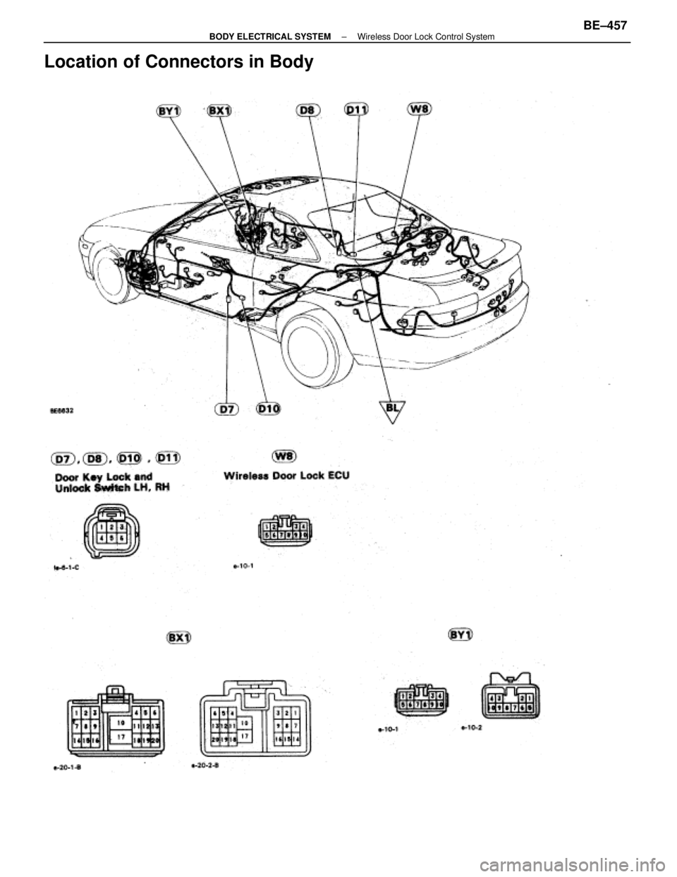
Location of Connectors in Body
±
BODY ELECTRICAL SYSTEM Wireless Door Lock Control SystemBE±457
WhereEverybodyKnowsYourName
Page 782 of 4087
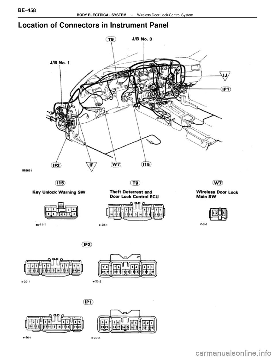
Location of Connectors in Instrument Panel
BE±458±
BODY ELECTRICAL SYSTEM Wireless Door Lock Control System
WhereEverybodyKnowsYourName
Page 783 of 4087
±
BODY ELECTRICAL SYSTEM Wireless Door Lock Control SystemBE±459
WhereEverybodyKnowsYourName
Page 784 of 4087
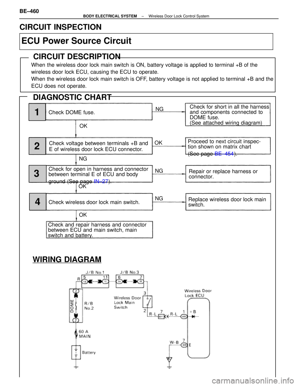
WIRING DIAGRAM
Check DOME fuse.NG
OK Check for short in all the harness
and components connected to
DOME fuse.
(See attached wiring diagram)
Check voltage between terminals +B and
E of wireless door lock ECU connector.
Check for open in harness and connector
between terminal E of ECU and body
ground (See page IN±27).
Check and repair harness and connector
between ECU and main switch, main
switch and battery. Check wireless door lock main switch. Proceed to next circuit inspec-
tion shown on matrix chart
(See page
BE±454).
Repair or replace harness or
connector.
Replace wireless door lock main
switch.
NG
NG
NG
OK
OK OK1
2
3
4
CIRCUIT INSPECTION
ECU Power Source Circuit
CIRCUIT DESCRIPTION
When the wireless door lock main switch is ON, battery voltage is applied to\
terminal +B of the
wireless door lock ECU, causing the ECU to operate.
When the wireless door lock main switch is OFF, battery voltage is not applied to terminal +B and the
ECU does not operate.
DIAGNOSTIC CHART
BE±460±
BODY ELECTRICAL SYSTEM Wireless Door Lock Control System
WhereEverybodyKnowsYourName
Page 785 of 4087
OKNG
NGOK
OKNG
OKNG
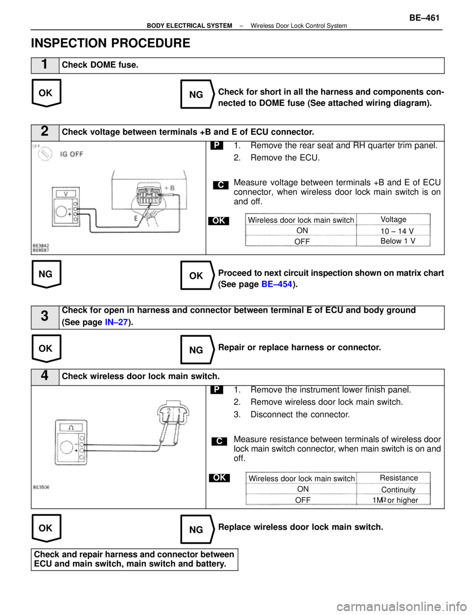
INSPECTION PROCEDURE
1Check DOME fuse.
Check for short in all the harness and components con-
nected to DOME fuse (See attached wiring diagram).
2Check voltage between terminals +B and E of ECU connector.
C
OK
P1. Remove the rear seat and RH quarter trim panel.
2. Remove the ECU.
Measure voltage between terminals +B and E of ECU
connector, when wireless door lock main switch is on
and off.
Wireless door lock main switchON
OFF Voltage
10 ± 14 V
Below 1 V
Proceed to
next circuit inspection shown on matrix chart
(See page BE±454).
3Check for open in harness and connector between terminal E of ECU and bo\
dy ground
(See page IN±27).
Repair or replace harness or connector.
4Check wireless door lock main switch.
C
OK
P1. Remove the instrument lower finish panel.
2. Remove wireless door lock main switch.
3. Disconnect the connector.
Measure resistance between terminals of wireless door
lock main switch connector, when main switch is on and
off.
Wireless door lock main switch
ON
OFF Resistance
Continuity
1M or higher
Replace wireless door lock main switch.
Check and repair harness and connector between
ECU and main switch, main switch and battery.
±
BODY ELECTRICAL SYSTEM Wireless Door Lock Control SystemBE±461
WhereEverybodyKnowsYourName
Page 786 of 4087
WIRING DIAGRAM
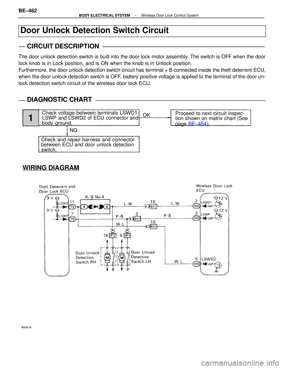
Door Unlock Detection Switch Circuit
CIRCUIT DESCRIPTION
The door unlock detection switch is built into the door lock motor assembly\
. The switch is OFF when the door
lock knob is in Lock position, and is ON when the knob is in Unlock posi\
tion.
Furthermore, the door unlock detection switch circuit has terminal + B connected ins\
ide the theft deterrent ECU,
when the door unlock detection switch is OFF, battery positive voltage is applied to the terminal of the door un-
lock detection switch circuit of the wireless door lock ECU.
DIAGNOSTIC CHARTDIAGNOSTIC CHART
NGOK
Proceed to next circuit inspec-
tion shown on matrix chart (See
page
BE±454 ).
Check voltage between terminals LSWD1
LSWP and LSWD2 of ECU connector and
body ground.
Check and repair harness and connector
between ECU and door unlock detection
switch.
1
BE±462±
BODY ELECTRICAL SYSTEM Wireless Door Lock Control System
WhereEverybodyKnowsYourName
Page 787 of 4087
NGOK
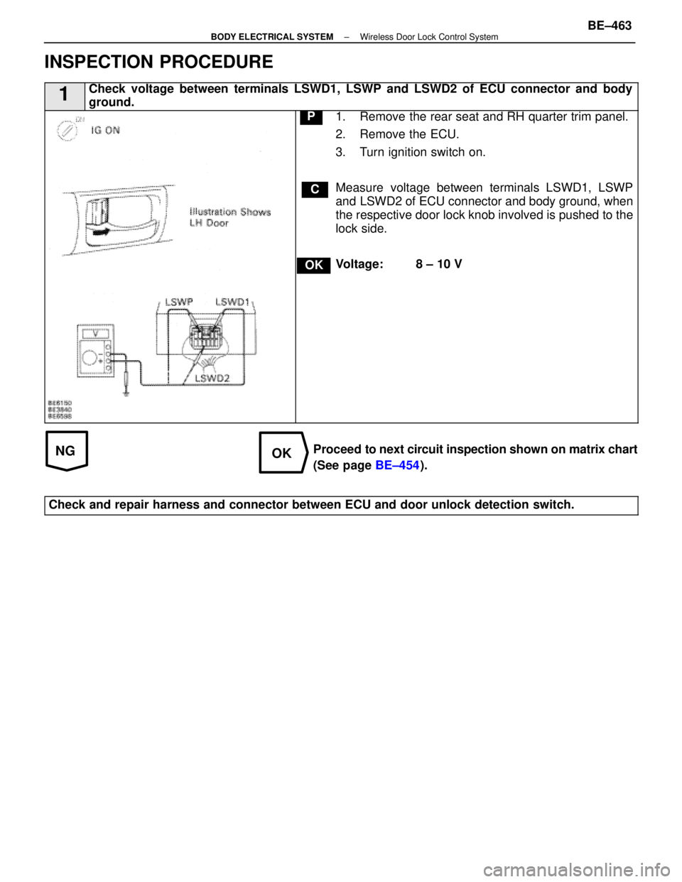
INSPECTION PROCEDURE
1Check voltage between terminals LSWD1, LSWP and LSWD2 of ECU connector a\
nd body
ground.
C
OK
P1. Remove the rear seat and RH quarter trim panel.
2. Remove the ECU.
3. Turn ignition switch on.
Measure voltage between terminals LSWD1, LSWP
and LSWD2 of ECU connector and body ground, when
the respective door lock knob involved is pushed to the
lock side.
Voltage: 8 ± 10 V
Proceed to next circuit inspection shown on matrix chart
(See page BE±454).
Check and repair harness and connector between ECU and door unlock detec\
tion switch.
±
BODY ELECTRICAL SYSTEM Wireless Door Lock Control SystemBE±463
WhereEverybodyKnowsYourName
Page 788 of 4087
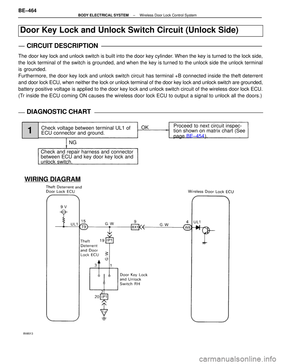
WIRING DIAGRAM
Door Key Lock and Unlock Switch Circuit (Unlock Side)
CIRCUIT DESCRIPTION
The door key lock and unlock switch is built into the door key cylinder. When the key is turned to the lock side,
the lock terminal of the switch is grounded, and when the key is turned to the unlock side the unlock terminal
is grounded.
Furthermore, the door key lock and unlock switch circuit has terminal +B\
connected inside the theft deterrent
and door lock ECU, when neither the lock or unlock terminal of the door key\
lock and unlock switch are grounded,
battery positive voltage is applied to the door key lock and unlock switch circuit of the wireless d\
oor lock ECU.
(Tr inside the ECU coming ON causes the wireless door lock ECU to output a \
signal to unlock all the doors.)
DIAGNOSTIC CHARTDIAGNOSTIC CHART
NGOK
Proceed to next circuit inspec-
tion shown on matrix chart (See
page
BE±454 ).
Check voltage between terminal UL1 of
ECU connector and ground.
Check and repair harness and connector
between ECU and key door key lock and
unlock switch.
1
BE±464±
BODY ELECTRICAL SYSTEM Wireless Door Lock Control System
WhereEverybodyKnowsYourName
Page 789 of 4087
NGOK
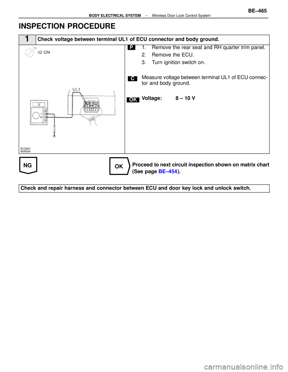
INSPECTION PROCEDURE
1Check voltage between terminal UL1 of ECU connector and body ground.
C
OK
P1. Remove the rear seat and RH quarter trim panel.
2. Remove the ECU.
3. Turn ignition switch on.
Measure voltage between terminal UL1 of ECU connec-
tor and body ground.
Voltage: 8 ± 10 V
Proceed to next circuit inspection shown on matrix chart
(See page BE±454).
Check and repair harness and connector between ECU and door key lock and\
unlock switch.
±
BODY ELECTRICAL SYSTEM Wireless Door Lock Control SystemBE±465
WhereEverybodyKnowsYourName
Page 790 of 4087
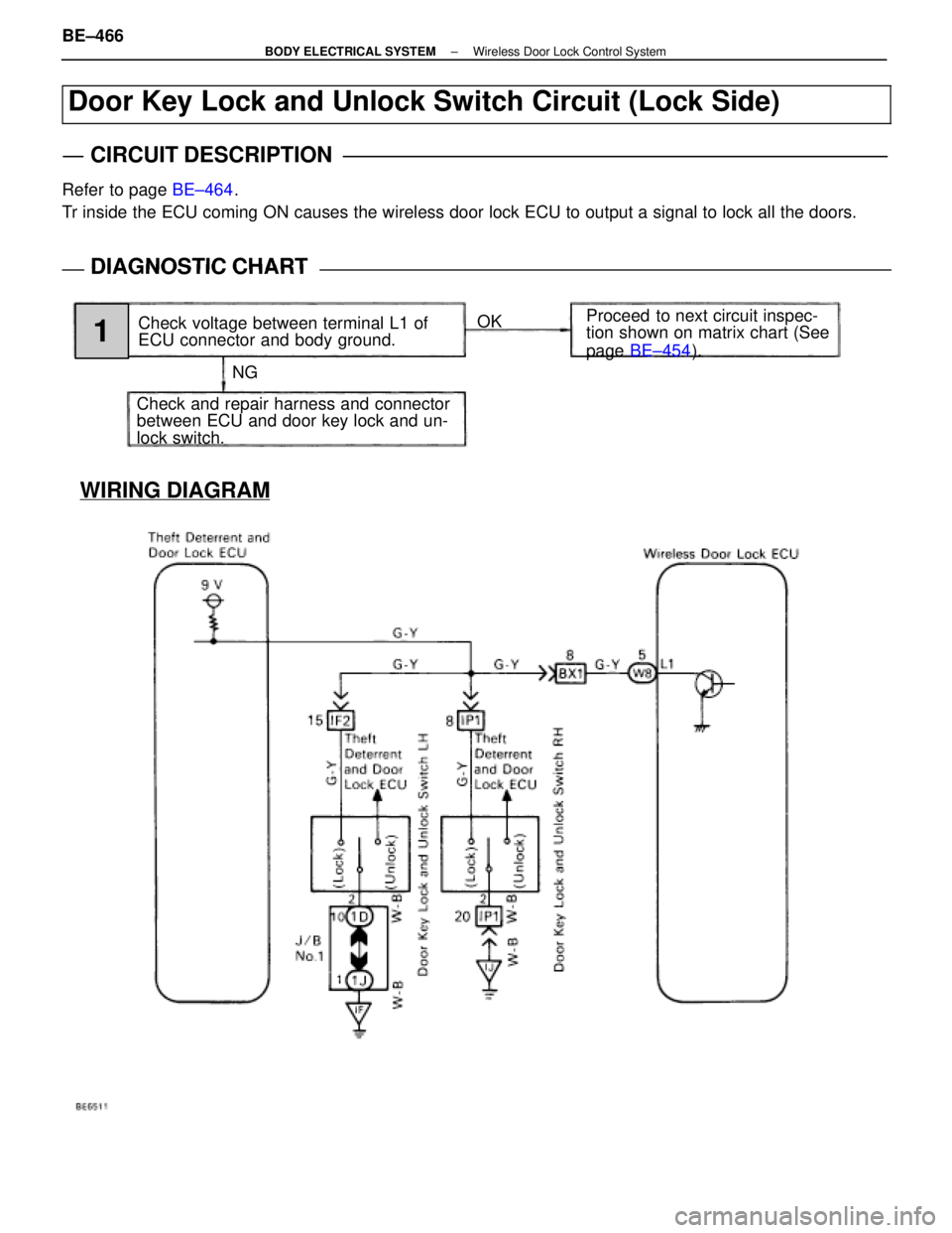
WIRING DIAGRAM
Door Key Lock and Unlock Switch Circuit (Lock Side)
CIRCUIT DESCRIPTION
Refer to page BE±464.
Tr inside the ECU coming ON causes the wireless door lock ECU to output a\
signal to lock all the doors.
DIAGNOSTIC CHARTDIAGNOSTIC CHART
NG OK
Proceed to next circuit inspec-
tion shown on matrix chart (See
page
BE±454 ).
Check voltage between terminal L1 of
ECU connector and body ground.
Check and repair harness and connector
between ECU and door key lock and un-
lock switch.
1
BE±466±
BODY ELECTRICAL SYSTEM Wireless Door Lock Control System
WhereEverybodyKnowsYourName
Trending: audio, ECO mode, wheel bolts, oil filter, washer fluid, towing, gas type
