LINCOLN CONTINENTAL 1996 Customer Assistance Guide
Manufacturer: LINCOLN, Model Year: 1996, Model line: CONTINENTAL, Model: LINCOLN CONTINENTAL 1996Pages: 320, PDF Size: 1.8 MB
Page 281 of 320

1.Make sure that the headlamp switch is in the
OFF position.
2.Lift the hood and remove the plastic sight
shield covering the back of the headlamps by
lifting up on the rear corners to release the
velcro attachments. Lift the shield and pull
towards the windshield.
3.At the back of the headlamp, pull up on the
two right angle brackets to release the
headlamp assembly from the vehicle.
4.Carefully pull the headlamp assembly away
from the vehicle to expose the back of the
bulb and wiring connector.
5.Remove the electrical connector from the bulb
by grasping the wire with a quick pull
rearward.6.Remove the retaining ring by turning it 1/8 of
a turn to free it from the socket. Then slide
the ring off the plastic base of the bad bulb.
Keep the ring. You must use it again to hold
the new bulb in place.
7.Carefully remove the bulb assembly from its
socket by gently pulling it rearward without
turning.
Installing the headlamp bulb
1.With the flat side of the bulb's plastic base
facing upward, insert the glass end of the bulb
into the socket. You may need to turn the
bulb left or right to line up the grooves in the
plastic base with the tabs in the socket. When
the grooves are aligned, push the bulb into the
socket until the plastic base contacts the rear
of the socket.
279
Page 282 of 320

2. Slip the bulb retaining ring over the plastic base
until it contacts the rear of the socket. Lock the
ring into the socket by rotating it clockwise
until you feel a "stop".
3. Push the electrical connector into the rear of
the plastic base until it snaps, locking it into
position
4. Carefully position the headlamp assembly onto
the vehicle making sure the alignment pins are
inserted into the proper holes
5. Hold the headlamp assembly snugly against the
vehicle and push down on the right angle
brackets to lock the lamp into position.
6. Install the plastic sight shield.
7. Turn the headlamps on and make sure that they
work properly. If the headlamp was correctly
aligned before you changed the bulb, you
should not need to align it again..
280Aiming Headlamps
Your vehicle is equipped with a Vehicle Headlamp
Aim Device (VHAD) on each headlamp body.
Each headlamp may be properly aimed in the
horizontal direction (left/right) and the vertical
position (up/down).
NOTE: A non-zero bubble reading does not
necessarily indicate out-of-aim headlamps. If your
vehicle is not positioned on a level surface, the
slope will be included in the level indicator.
Therefore, vertical headlamp adjustment should be
Tools required: One 4mm socket and ratchet.
The Horizontal aim must be adjusted first.
Page 283 of 320

NOTE: The following procedure assumes that
the vehicle's front structure is in factory alignment
condition. If the vehicle has been in an accident
requiring the front end of the vehicle to be
repaired, the horizontal indicator should be
recalibrated by the servicing facility.
Before adjusting your headlamps, you must make
sure that the air suspension has been adjusted to
the proper ride height. In order to do this:
1.Position the vehicle on a level surface.
2.Make sure the air suspension switch in the
luggage compartment is in the ON position.
3.Turn the ignition key to the ON position.
4. Open and close the driver's door to allow the
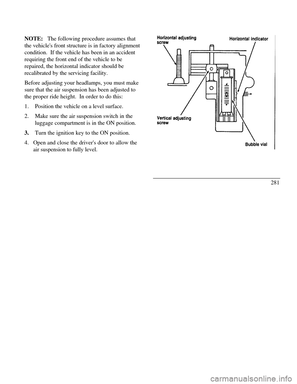
air suspension to fully level.Hori
zontal adjusting screw Vertical adjusting screw Horizontal indicator Bubble vial
281
Page 284 of 320

Horizontal aim adjustment
1.Open the hood and lift the front end cover
from its velcro attachments. Locate the
horizontal level indicator and adjustment
screw.
2.Use a 4mm socket and ratchet to turn the
horizontal adjusting screw until the horizontal
indicator is in line with the "0" reference.
282Vertical aim adjustment
NOTE: The numbers shown on the vial indicate
beam direction in degrees up or down.
1.Locate the vertical level indicator and adjustment
screw.
2.Use a 4mm socket and ratchet to turn the vertical
adjustment screw until the bubble in the
horizontal level indicator is centered in the vial.
3. Replace the front end cover and close the hood.
Page 285 of 320

Bulb specifications
FunctionTrade numberExterior illuminationBackup lamp3156Cornering lamp3156Headlamp9007High-mount brakelamp912License plate lamp168Luggage compartment lamp912Side marker - front lamp916NA*Side marker - rear lamp194Turn signal and park lamp - front3457NA*Turn signal, stoplamp and tail lamp
- rear3157Redundant turn - rear3157Decklid reflector168Instrument panel lightsElectronic automatic temperature
control***Air bag readiness light37Anti-lock warning lamp37And-theft warning lamp37Ash receptacle1445Ash ttay - rear doors37Clock***FunctionTradenumberInstrument panel lights (continued)Cluster illumination***Cluster control button37Compact disc player**Glove compartment194Headlamp switch nomenclature37Message center control buttons***“PRN@D I" bulb (floor console)194Rear window defrost switchnomenclature37Radio**Warning lights (cluster)37Interior courtesy lampsCigar lighter (door mounted)1893Door mounted lamp (front and rear)214-2Illuminated visor mirror (passenger)74Overhead console-reading lamps (without
moon roof)211-2Passenger assist handle (rear seat)211-2Under instrument panel906*NA means Natural Amber.
**Refer bulb replacement to a Ford -authorized radio service
center.
***Refer bulb replacement to a Ford or Lincoln-Mercury
dealer.
283
Page 286 of 320

Emission Control System
Your vehicle is equipped with three (3) catalytic
converters which are used to enable your vehicle to
comply with applicable exhaust emissions
requirements./!\ WARNINGExhaust leaks may result in the entry ofharmful and potentially lethal fumes into thepassenger compartment. Under extremeconditions excessive exhaust temperaturescould damage the fuel system, the interiorfloor covering, or other vehicle components,possibly causing a fire.To make sure that the catalytic converters and the
other emissions control parts continue to work
properly: Use only premium unleaded fuel.
284 Avoid running out of fuel. Do not turn off the ignition while your vehicle is
moving, especially at high speeds. Do not push start your vehicle. Have the services listed in the Maintenance
Schedule and Record booklet performed according
to the specified schedule. The scheduled
maintenance services are required because they are
considered essential to the life and performance of
your vehicle and to its emissions system.
In general, maintenance, replacement, or service of
the emissions control devices or systems in your new
Ford Motor Company vehicle or engine may be
performed at your expense by any automotive repair
establishment or individual using automotive parts
equivalent to those which your vehicle or engine was
originally equipped.
Page 287 of 320

Ford strongly recommends the use of genuine Ford
replacement parts. If other than Ford or
Motorcraft parts or Ford authorized
remanufactured parts are used for maintenance
replacements or for the service of components
affecting emission control, such non-Ford parts
should be equivalent to genuine Ford Motor
Company parts in performance and durability. It is
the owner's responsibility to determine the
equivalency of such parts. Please consult your
warranty booklet for complete warranty
information./!\ WARNINGDo not park, idle, or drive your vehicle in drygrass or other dry ground cover. Theemission system heats up the enginecompartment and exhaust system, which canstart a fire.Watch for fluid leaks, strange odors, smoke, loss
of oil pressure, the charge warning light, the checkengine light, or the temperature warning light. These
sometimes indicate that the emission system is not
working properly.
Do not make any unauthorized changes to your
vehicle or engine. Changes that cause more unburned
fuel to reach the exhaust system can increase the
temperature of the engine or exhaust system.
By law, anyone who manufactures, repairs, services,
sells, leases, trades vehicles, or supervises a fleet of
vehicles is not permitted to intentionally remove an
emission control device or prevent it from working.
In some of the United States and in Canada, vehicle
owners may be liable if their emission control device
is removed or is prevented from working.
Do not drive your vehicle if it does not operate
properly. See your dealer if the engine runs on for
more than five seconds after you shut it off or if it
misfires, surges, stalls, or backfires.
285
Page 288 of 320

Information about your vehicle's emission control
system is on the Vehicle Emission Control
Information decal located on or near the engine.
This decal identifies engine displacement and gives
some tune-up specifications.
Readiness for Inspection/Maintenance
Testing
In some localities it may become a legal requirement
to pass an Inspection/Maintenance (I/M) test of the
On-Board Diagnostic (OBD) II system. If the
vehicle's powertrain system or its battery has just
been serviced, the OBD II system is reset to a not
ready for I/M testing condition. To prepare for I/M
testing, the law specifies a "need for additional
mixed city and highway driving to complete the
check" of the OBD II system. As soon as all of the
OBD II system checks are successfully completed,
the OBD II system is set to the ready condition. The
amount of driving required to reach the ready
condition varies with individual driving patterns. To
complete this requirement in theminimum amount of time, refer to the OBD II Drive
Cycle defined below. If the vehicle owner cannot or
does not want to do the additional driving required by
law, a service center can perform this drive cycle as it
would any other type of repair work.
OBD II Drive Cycle
The following steps must be run in the order shown.
If steps 2 through 9 are interrupted, repeat the
preceeding step. Any safe driving mode is acceptable
between steps.
Always drive vehicle in a safe manner according to
traffic conditions and obey all traffic laws.
1. Start engine and drive until engine has reached
normal operating temperature.
2. Idle vehicle for at least 80 seconds, then
accelerate at part throttle to near 45 mph (72 km/h).
286
Page 289 of 320

3.Drive to accumulate at least four (4) minutes
in the range of 30-45 mph (50-70 km/h). If
stop and go conditions occur, the
accumulative time must be within the 30-45
mph (50-70 km/h) range. No wide open
throttle conditions should be encountered.
4.Cruise and maintain a select speed in the range
of 30-40 mph (48-64 km/h) on a level road
with throttle held very steady for at least one
(1) minute.
5.Decelerate and idle for at least 80 seconds.
6.Accelerate to 55 mph (90 km/h) at ½ throttle.
7.Decelerate at closed throttle for I 0 seconds.
8. Cruise and maintain a select speed in the range
of 40-65 mph (64-105 km/h) on a level road
with throttle held very steady for at least 80
seconds.9. Complete 10 minutes of city driving 25-40 mph
(40-64 kin/h) with at least six (6) stops.
10. OBD II drive cycle has been completed.
Vehicle can be turned off when convenient.
Refill Capacities, Motorcraft Parts,
and Lubricant Specifications
Refill Capacities
ComponentU.S.MetricCooling system
(including heater)14.25 qts.13.5 litersEngine oil
(with filter change)6.0 qts.5.7 litersTransaxle
Auto. overdrive13.7 qts.13.0 litersPower steering2.5 pints1.2 litersFuel tank17.8 gallons67.4 litersPressure cap16 psiI 10 kPa287
Page 290 of 320

Motorcraft Parts
If you replace
these parts ...Use the Motorcraft Service
Part with this part number· spark plug*AWSF-32EE**· air filterFA-1615· fuel filterFG-800A· oil filterFL-820· batterystandardBXT-65-850*Refer to Vehicle Emission Control Information (VECI)
decal for spark plug and gap specifications.
**If a spark plug is removed for examination, it must be
reinstalled in the same cylinder.
Cylinders #1, #2, 43, #4 have a EG suffix.
Cylinders #5, #6, #7, #8 have a E suffix.
If a spark plug needs to be replaced, use only spark plugs
with the I service number suffix letter "FE" as shown on the
engine decal.288