LINCOLN MKZ 2014 Owners Manual
Manufacturer: LINCOLN, Model Year: 2014, Model line: MKZ, Model: LINCOLN MKZ 2014Pages: 468, PDF Size: 4.49 MB
Page 281 of 468
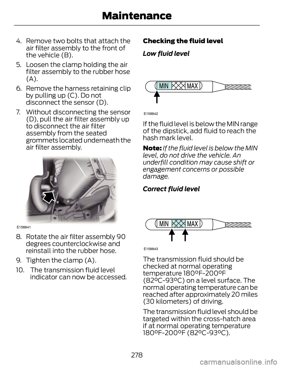
4. Remove two bolts that attach theair filter assembly to the front of
the vehicle (B).
5. Loosen the clamp holding the air filter assembly to the rubber hose
(A).
6. Remove the harness retaining clip by pulling up (C). Do not
disconnect the sensor (D).
7. Without disconnecting the sensor (D), pull the air filter assembly up
to disconnect the air filter
assembly from the seated
grommets located underneath the
air filter assembly.
E158841
8. Rotate the air filter assembly 90degrees counterclockwise and
reinstall into the rubber hose.
9. Tighten the clamp (A).
10. The transmission fluid level indicator can now be accessed. Checking the fluid level
Low fluid level
E158842
If the fluid level is below the MIN range
of the dipstick, add fluid to reach the
hash mark level.
Note:
If the fluid level is below the MIN
level, do not drive the vehicle. An
underfill condition may cause shift or
engagement concerns or possible
damage.
Correct fluid level
E158843
The transmission fluid should be
checked at normal operating
temperature 180°F-200°F
(82°C-93°C) on a level surface. The
normal operating temperature can be
reached after approximately 20 miles
(30 kilometers) of driving.
The transmission fluid level should be
targeted within the cross-hatch area
if at normal operating temperature
180°F-200°F (82°C-93°C).
278
Maintenance
Page 282 of 468
High fluid level
E158844
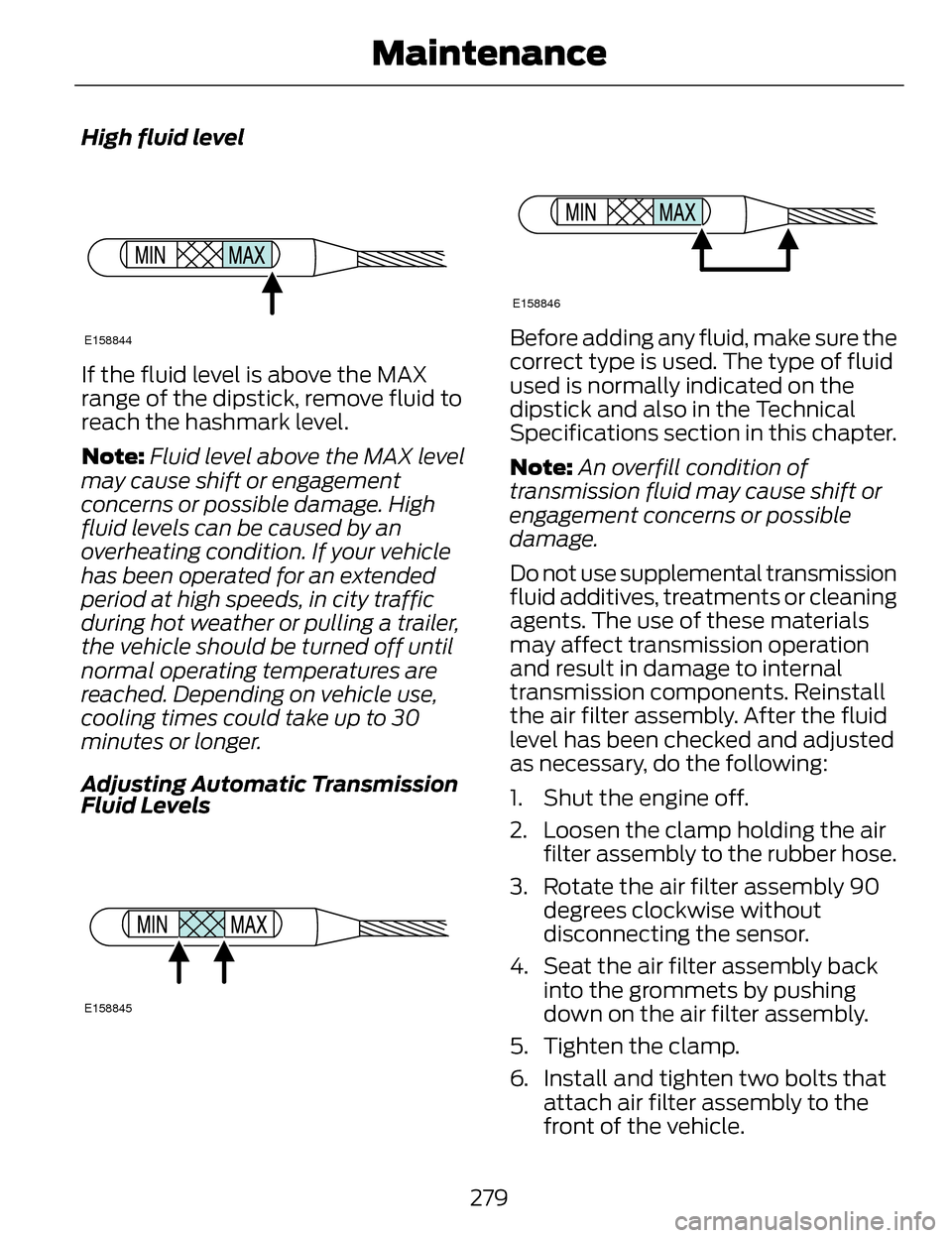
If the fluid level is above the MAX
range of the dipstick, remove fluid to
reach the hashmark level.
Note:Fluid level above the MAX level
may cause shift or engagement
concerns or possible damage. High
fluid levels can be caused by an
overheating condition. If your vehicle
has been operated for an extended
period at high speeds, in city traffic
during hot weather or pulling a trailer,
the vehicle should be turned off until
normal operating temperatures are
reached. Depending on vehicle use,
cooling times could take up to 30
minutes or longer.
Adjusting Automatic Transmission
Fluid Levels
E158845
E158846
Before adding any fluid, make sure the
correct type is used. The type of fluid
used is normally indicated on the
dipstick and also in the Technical
Specifications section in this chapter.
Note: An overfill condition of
transmission fluid may cause shift or
engagement concerns or possible
damage.
Do not use supplemental transmission
fluid additives, treatments or cleaning
agents. The use of these materials
may affect transmission operation
and result in damage to internal
transmission components. Reinstall
the air filter assembly. After the fluid
level has been checked and adjusted
as necessary, do the following:
1. Shut the engine off.
2. Loosen the clamp holding the air filter assembly to the rubber hose.
3. Rotate the air filter assembly 90 degrees clockwise without
disconnecting the sensor.
4. Seat the air filter assembly back into the grommets by pushing
down on the air filter assembly.
5. Tighten the clamp.
6. Install and tighten two bolts that attach air filter assembly to the
front of the vehicle.
279
Maintenance
Page 283 of 468
7. Install the bolt cover (if equipped).
8. Reinstall the harness retaining clip into the front of the air filter
assembly.
BRAKE FLUID CHECK
Fluid levels between the MIN and MAX
lines are within the normal operating
range; there is no need to add fluid. If
the fluid levels are outside of the
normal operating range, the
performance of the system could be
compromised; seek service from your
authorized dealer immediately.
POWER STEERING FLUID
CHECK
Your vehicle is equipped with an
electric power steering (EPS) system.
There is no fluid reservoir to check or
fill.
FUEL FILTER
Your vehicle is equipped with a
lifetime fuel filter that is integrated
with the fuel tank. Regular
maintenance or replacement is not
needed.
WASHER FLUID CHECK
WARNING
If you operate your vehicle in
temperatures below 40°F (5°C),
use washer fluid with antifreeze
protection. Failure to use washer fluid
with antifreeze protection in cold
weather could result in impaired
windshield vision and increase the risk
of injury or accident.
Note: The front and rear washer
systems are supplied from the same
reservoir.
Add fluid to fill the reservoir if the level
is low. Only use a washer fluid that
meets Ford specifications. See
Capacities and Specifications
(page 329).
State or local regulations on volatile
organic compounds may restrict the
use of methanol, a common
windshield washer antifreeze additive.
Washer fluids containing
non-methanol antifreeze agents
should be used only if they provide
cold weather protection without
damaging the vehicle’s paint finish,
wiper blades or washer system.
280
Maintenance
Page 284 of 468
CHANGING THE 12V
BATTERY
WARNINGS
Batteries normally produce
explosive gases which can cause
personal injury. Therefore, do not
allow flames, sparks or lighted
substances to come near the battery.
When working near the battery,
always shield your face and protect
your eyes. Always provide proper
ventilation.
When lifting a plastic-cased
battery, excessive pressure on
the end walls could cause acid to flow
through the vent caps, resulting in
personal injury and damage to the
vehicle or battery. Lift the battery with
a battery carrier or with your hands on
opposite corners.
Keep batteries out of reach of
children. Batteries contain
sulfuric acid. Avoid contact with skin,
eyes or clothing. Shield your eyes
when working near the battery to
protect against possible splashing of
acid solution. In case of acid contact
with skin or eyes, flush immediately
with water for a minimum of 15
minutes and get prompt medical
attention. If acid is swallowed, call a
physician immediately.
Your vehicle is equipped with a
Motorcraft® maintenance-free
battery which normally does not
require additional water during its life
of service. Note:
If your battery has a
cover/shield, make sure it is reinstalled
after the battery has been cleaned or
replaced.
Note: See an authorized dealer for low
voltage battery access, testing, or
replacement.
When a low voltage battery
replacement is necessary, see an
authorized dealer to replace the low
voltage battery with a Ford
recommended replacement low
voltage battery that matches the
electrical requirements of the vehicle
To ensure proper operation of the
battery management system (BMS),
do not allow a technician to connect
any electrical device ground
connection directly to the low voltage
battery negative post. A connection
at the low voltage battery negative
post can cause inaccurate
measurements of the battery
condition and potential incorrect
system operation.
Note: If a person adds electrical or
electronic accessories or components
to the vehicle, the accessories or
components may adversely affect the
low voltage battery performance and
durability and may also affect the
performance of other electrical
systems in the vehicle.
For longer, trouble-free operation,
keep the top of the battery clean and
dry. Also, make certain the battery
cables are always tightly fastened to
the battery terminals.
281
Maintenance
Page 285 of 468
If you see any corrosion on the battery
or terminals, remove the cables from
the terminals and clean with a wire
brush. You can neutralize the acid with
a solution of baking soda and water.
When a battery replacement is
required, the battery should only be
replaced with a Ford recommended
replacement battery that matches
the electrical requirements of the
vehicle.
Because your vehicle’s engine is
electronically-controlled by a
computer, some engine control
settings are maintained by power
from the low voltage battery. Some
engine computer settings, like the idle
trim and fuel trim strategy, optimize
the driveability and performance of
the engine. Some other computer
settings, like the clock and radio
station presets, are also maintained
in memory by power from the low
voltage battery. When a technician
disconnects and connects the low
voltage battery, these settings are
erased. Complete the following
procedure in order to restore the
settings:
1. With the vehicle at a completestop, set the parking brake.
2. Shift the transmission into P.
3. Turn off all accessories.
4. Step on the brake pedal and start the vehicle. 5. Run the engine until it reaches
normal operating temperature.
While the engine is warming up,
complete the following: Reset the
clock. See Audio System (page
124). Reset the power windows
bounce-back feature. See
Windows and Mirrors (page 88).
Reset the radio station presets.
See Audio System (page 124).
6. Allow the engine to idle for at least one minute. If the engine turns off,
step on the accelerator to start the
engine.
7. While the engine is running, step on the brake pedal and shift the
transmission to N.
8. Allow the engine to run for at least one minute by pressing on the
accelerator pedal.
9. Drive the vehicle at least 10 miles (16 kilometers) to completely
relearn the idle and fuel trim
strategy.
Note: If you do not allow the engine to
relearn the idle and fuel trim strategy,
the idle quality of your vehicle may be
adversely affected until the engine
computer eventually relearns the idle
trim and fuel trim strategy.
Note: Always dispose of automotive
batteries in a responsible manner.
Follow your local authorized standards
for disposal. Call your local authorized
recycling center to find out more about
recycling automotive batteries.
282
Maintenance
Page 286 of 468
Note:It is recommended that the
negative battery cable terminal be
disconnected from the battery if you
plan to store your vehicle for an
extended period of time.
CHECKING THE WIPER
BLADES
E142463
Run the tip of your fingers over the
edge of the blade to check for
roughness.
Clean the wiper blades with washer
fluid or water applied with a soft
sponge or cloth.
CHANGING THE WIPER
BLADES
The wiper arms can be manually
moved when the ignition is off. This
allows for ease of blade replacement
and cleaning under the blades.
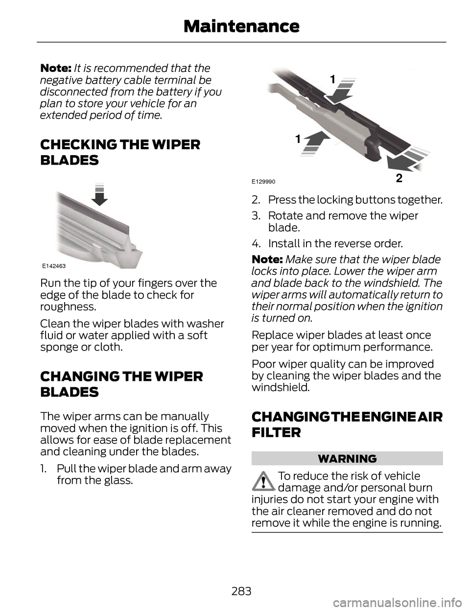
1. Pull the wiper blade and arm away from the glass.
E129990
1
1 2
2. Press the locking buttons together.
3. Rotate and remove the wiperblade.
4. Install in the reverse order.
Note: Make sure that the wiper blade
locks into place. Lower the wiper arm
and blade back to the windshield. The
wiper arms will automatically return to
their normal position when the ignition
is turned on.
Replace wiper blades at least once
per year for optimum performance.
Poor wiper quality can be improved
by cleaning the wiper blades and the
windshield.
CHANGING THE ENGINE AIR
FILTER
WARNING
To reduce the risk of vehicle
damage and/or personal burn
injuries do not start your engine with
the air cleaner removed and do not
remove it while the engine is running.
283
Maintenance
Page 287 of 468
When changing the air filter element,
use only the air filter element listed.
See Capacities and Specifications
(page 329).
For EcoBoost equipped vehicles:
When servicing the air cleaner, it is
important that no foreign material
enter the air induction system. The
engine and turbocharger are
susceptible to damage from even
small particles.
Change the air filter element at the
proper interval. See Scheduled
Maintenance (page 436).
Note: Failure to use the correct air filter
element may result in severe engine
damage. The customer warranty may
be void for any damage to the engine
if the correct air filter element is not
used.
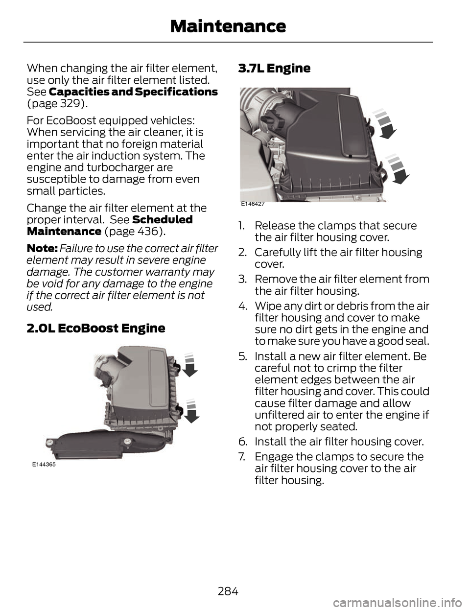
2.0L EcoBoost Engine
E144365
3.7L Engine
E146427
1. Release the clamps that secure the air filter housing cover.
2. Carefully lift the air filter housing cover.
3. Remove the air filter element from the air filter housing.
4. Wipe any dirt or debris from the air filter housing and cover to make
sure no dirt gets in the engine and
to make sure you have a good seal.
5. Install a new air filter element. Be careful not to crimp the filter
element edges between the air
filter housing and cover. This could
cause filter damage and allow
unfiltered air to enter the engine if
not properly seated.
6. Install the air filter housing cover.
7. Engage the clamps to secure the air filter housing cover to the air
filter housing.
284
Maintenance
Page 288 of 468
ADJUSTING THE
HEADLAMPS
Vertical Aim Adjustment
The headlamps on your vehicle are
properly aimed at the assembly plant.
If your vehicle has been in an accident,
the alignment of your headlamps
should be checked by your authorized
dealer.
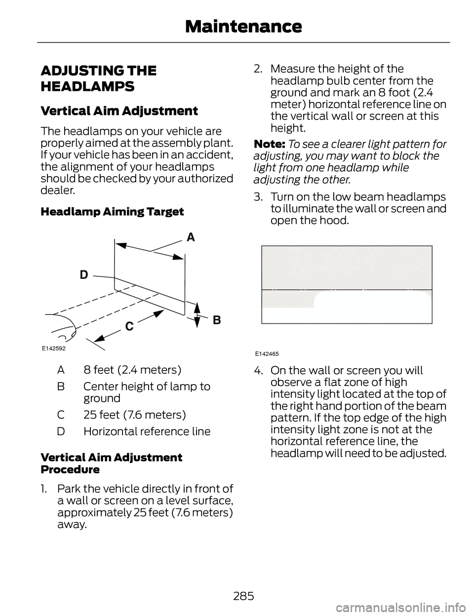
Headlamp Aiming Target
E142592
8 feet (2.4 meters)
A
Center height of lamp to
ground
B
25 feet (7.6 meters)
C
Horizontal reference line
D
Vertical Aim Adjustment
Procedure
1. Park the vehicle directly in front of a wall or screen on a level surface,
approximately 25 feet (7.6 meters)
away. 2. Measure the height of the
headlamp bulb center from the
ground and mark an 8 foot (2.4
meter) horizontal reference line on
the vertical wall or screen at this
height.
Note: To see a clearer light pattern for
adjusting, you may want to block the
light from one headlamp while
adjusting the other.
3. Turn on the low beam headlamps to illuminate the wall or screen and
open the hood.
E142465
4. On the wall or screen you willobserve a flat zone of high
intensity light located at the top of
the right hand portion of the beam
pattern. If the top edge of the high
intensity light zone is not at the
horizontal reference line, the
headlamp will need to be adjusted.
285
Maintenance
Page 289 of 468
E150095
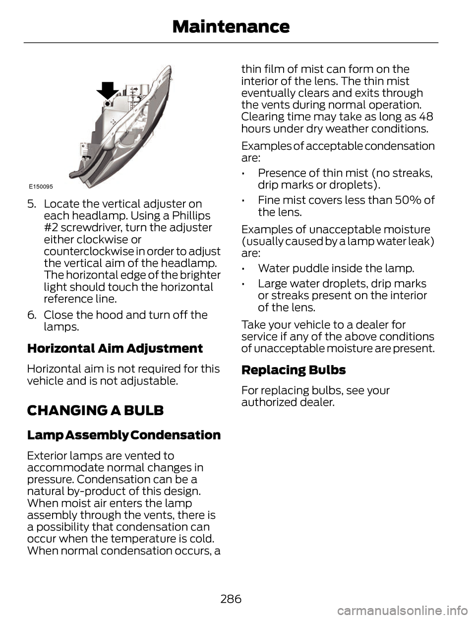
5. Locate the vertical adjuster oneach headlamp. Using a Phillips
#2 screwdriver, turn the adjuster
either clockwise or
counterclockwise in order to adjust
the vertical aim of the headlamp.
The horizontal edge of the brighter
light should touch the horizontal
reference line.
6. Close the hood and turn off the lamps.
Horizontal Aim Adjustment
Horizontal aim is not required for this
vehicle and is not adjustable.
CHANGING A BULB
Lamp Assembly Condensation
Exterior lamps are vented to
accommodate normal changes in
pressure. Condensation can be a
natural by-product of this design.
When moist air enters the lamp
assembly through the vents, there is
a possibility that condensation can
occur when the temperature is cold.
When normal condensation occurs, a thin film of mist can form on the
interior of the lens. The thin mist
eventually clears and exits through
the vents during normal operation.
Clearing time may take as long as 48
hours under dry weather conditions.
Examples of acceptable condensation
are:
• Presence of thin mist (no streaks,
drip marks or droplets).
• Fine mist covers less than 50% of the lens.
Examples of unacceptable moisture
(usually caused by a lamp water leak)
are:
• Water puddle inside the lamp.
• Large water droplets, drip marks or streaks present on the interior
of the lens.
Take your vehicle to a dealer for
service if any of the above conditions
of unacceptable moisture are present.
Replacing Bulbs
For replacing bulbs, see your
authorized dealer.
286
Maintenance
Page 290 of 468
BULB SPECIFICATION
CHART
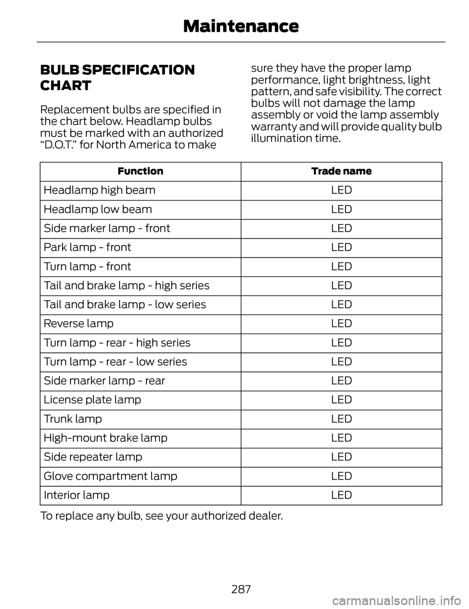
Replacement bulbs are specified in
the chart below. Headlamp bulbs
must be marked with an authorized
“D.O.T.” for North America to makesure they have the proper lamp
performance, light brightness, light
pattern, and safe visibility. The correct
bulbs will not damage the lamp
assembly or void the lamp assembly
warranty and will provide quality bulb
illumination time.
Trade name
Function
LED
Headlamp high beam
LED
Headlamp low beam
LED
Side marker lamp - front
LED
Park lamp - front
LED
Turn lamp - front
LED
Tail and brake lamp - high series
LED
Tail and brake lamp - low series
LED
Reverse lamp
LED
Turn lamp - rear - high series
LED
Turn lamp - rear - low series
LED
Side marker lamp - rear
LED
License plate lamp
LED
Trunk lamp
LED
High-mount brake lamp
LED
Side repeater lamp
LED
Glove compartment lamp
LED
Interior lamp
To replace any bulb, see your authorized dealer.
287
Maintenance