MASERATI LEVANTE 2019 Owners Manual
Manufacturer: MASERATI, Model Year: 2019, Model line: LEVANTE, Model: MASERATI LEVANTE 2019Pages: 436, PDF Size: 15.24 MB
Page 351 of 436

6 – In an Emergency ToolKit .............................................. 348
Hazard Warning Flashers ................................. 350
In the Event of an Accident ............................... 350
In case of a Punctured Tire ................................ 351
Emergency Release of the Parking Brake ..................... 356
Transmission Manual Release of P (Park) Position ............... 356
Auxiliary Jump-Start Procedure ............................ 357
Towing a Disabled Vehicle ................................ 360
347
Page 352 of 436
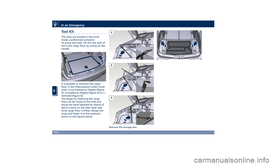
Tool Kit The tools are located in the trunk
inside a preformed container.
To access the tools, lift the rear part of
the trunk cargo floor, by acting on the
handle.
It is possible to maintain the cargo
floor in the lifted position when trunk
cover is not hooked to liftgate (figure
1 ), is hooked to liftgate (figure 2 )oris
removed (figure 3 ).
The straps for fastening the cargo
floor can be found at the ends and
along the band fastened by means of
Velcro inserts on the floor back side.
Once cargo floor is lifted, release the
strap and fasten it at the positions
shown in the figures below.
Remove the storage box.In an Emergency
6
348
Page 353 of 436
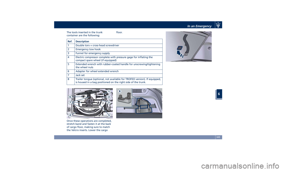
The tools inserted in the trunk
container are the following:
Once these operations are completed,
stretch band and fasten it at the back
of cargo floor, making sure to match
the Velcro inserts. Lower the cargo floor.
Ref. Description
1 Double torx + cross-head screwdriver
2 Emergency tow hook
3 Funnel for emergency supply
4 Electric compressor complete with pressure gage for inflating the
compact spare wheel (if equipped)
5 Extended wrench with rubber-coated handle for unscrewing/tightening
the wheel nuts
6 Adapter for wheel extended wrench
7 Jack set
8 Trailer tongue (optional, not available for TROFEO version). If equipped,
is housed in a bag positioned on the right side of the trunk. In an Emergency
6
349
Page 354 of 436
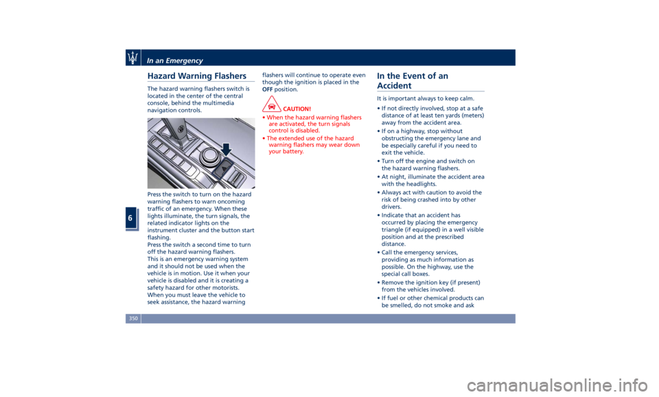
Hazard Warning Flashers The hazard warning flashers switch is
located in the center of the central
console, behind the multimedia
navigation controls.
Press the switch to turn on the hazard
warning flashers to warn oncoming
traffic of an emergency. When these
lights illuminate, the turn signals, the
related indicator lights on the
instrument cluster and the button start
flashing.
Press the switch a second time to turn
off the hazard warning flashers.
This is an emergency warning system
and it should not be used when the
vehicle is in motion. Use it when your
vehicle is disabled and it is creating a
safety hazard for other motorists.
When you must leave the vehicle to
seek assistance, the hazard warning flashers will continue to operate even
though the ignition is placed in the
OFF position.
CAUTION!
• When the hazard warning flashers
are activated, the turn signals
control is disabled.
• The extended use of the hazard
warning flashers may wear down
your battery.
In the Event of an
Accident It is important always to keep calm.
• If not directly involved, stop at a safe
distance of at least ten yards (meters)
away from the accident area.
• If on a highway, stop without
obstructing the emergency lane and
be especially careful if you need to
exit the vehicle.
• Turn off the engine and switch on
the hazard warning flashers.
• At night, illuminate the accident area
with the headlights.
• Always act with caution to avoid the
risk of being crashed into by other
drivers.
• Indicate that an accident has
occurred by placing the emergency
triangle (if equipped) in a well visible
position and at the prescribed
distance.
• Call the emergency services,
providing as much information as
possible. On the highway, use the
special call boxes.
• Remove the ignition key (if present)
from the vehicles involved.
• If fuel or other chemical products can
be smelled, do not smoke and askIn an Emergency
6
350
Page 355 of 436
people around you to put their
cigarettes out.
• To extinguish fires, even small ones,
use a fire extinguisher, blankets,
sand or earth. Never use water.
• In multiple accidents occurred on
highways, particularly where
visibility is poor, there is a high risk
of being involved in other collisions.
Leave the vehicle immediately and
move away from the area.
In case of Injured Persons • Never leave the injured person
alone. Persons not directly involved
in the accident are also required to
give assistance.
• Do not crowd around injured
persons.
• Reassure the injured person that
help is on the way.
WARNING!
California Proposition 65
Operating, servicing and maintaining
a passenger vehicle or off-road vehicle
can expose you to chemicals including
such as, engine exhaust, carbon
monoxide, phthalates and lead, that
which are known to the State of
California to cause cancer and birth defects or other reproductive harm. To
minimize exposure, avoid breathing
exhaust, do not idle the engine except
as necessary, service your vehicle in a
well-ventilated area and wear gloves
or wash your hands frequently when
servicing your vehicle. For more
information go to:
www.P65Warnings.ca.gov/passenger-
vehicle
In case of a Punctured Tire The vehicle is equipped with a
compact spare wheel.
Using the Compact Spare
Wheel The automatic leveling of pneumatic
suspensions might create problems
when it is necessary to lift the vehicle
to replace the wheel featuring
punctured tire with the emergency
wheel supplied or with another wheel.
CAUTION!
Before mounting the compact spare
wheel it is necessary to disable the
suspension system by scrolling the user
settings on MTC+ and selecting
“Wheel Replacement Mode” in
“Suspensions” submenu. The tick next
to selected item will indicate that this
mode is active and pneumatic
suspension system is disabled (for
further details, refer to “MTC+
Settings” chapter in section
“Dashboard Instruments and
Controls”). After servicing, restore
original conditions and eliminate the
tick next to selected mode: in this way
the pneumatic suspension system willIn an Emergency
6
351
Page 356 of 436
(Continued)
go back to normal operation.
NOTE:
The compact spare wheel is supplied in
aluminum or steel: the pictures show
the one in aluminum.
The compact spare wheel is stored in
the trunk and is supplied deflated in
order to limit the amount of space
occupied. An electric compressor is also
provided for inflating. In the event of
a tire puncture, proceed as follows.
• Stop the vehicle in a place that does
not constitute a danger to traffic and
where the wheel can be changed
safely. The vehicle must be level and
on firm ground.
• Select the P (Park) mode and then
engage manually the electric parking
brake and move the ignition switch
to OFF position.
• If necessary, turn the hazard warning
flashers on and place the warning
triangle (if equipped) at the required
distance.
WARNING!
• The jack should be used on level firm
ground wherever possible. • It is recommended that the wheels
of the vehicle be chocked, and that
no person should remain in a vehicle
that is being jacked.
• If the vehicle has been stopped on a
slope or an uneven surface, place
chocks or other suitable items in
front of or behind the wheels to
stop the vehicle from moving.
• Never start or run the engine with
the vehicle on a jack.
• No person should place any portion
of their body under a vehicle that is
supported by a jack.
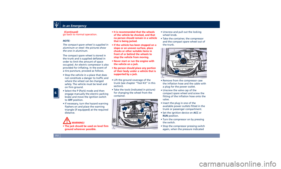
• Lift the ground coverage of the
trunk
(see chapter “T ool Kit” in this
section).
• Take the tools (indicated in picture)
for changing the wheel from the
container. • Unscrew and pull out the locking
wheel knob.
• Take the container, the compressor
and the compact spare wheel out of
the trunk.
• Remove from the compressor case
the inflation hose and the cable with
a plug for the power outlet.
• Unscrew the valve cap of the
compact spare wheel and screw the
fitting of the inflation hose onto the
valve.
• Insert the plug in one of the
available power outlets fitted in the
trunk or passenger compartment.
• Set the ignition device on ACC or
RUN position.
• Turn the compressor on by pressing
the switch.
• Stop the compressor pressing switch
again, when the pressure indicatedIn an Emergency
6
352
Page 357 of 436
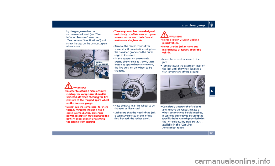
by the gauge reaches the
recommended level (see “Tire
Inflation Pressure” in section
“Features and Specifications”) and
screw the cap on the compact spare
wheel valve.
WARNING!
• In order to obtain a more accurate
reading, the compressor should be
switched off when checking the tire
pressure of the compact spare wheel
on the pressure gauge.
• Do not run the compressor for more
than 20 minutes: there is a risk it
could overheat. Also, prolonged
power absorption may discharge the
battery, subsequently preventing
the engine from starting. • The compressor has been designed
exclusively to inflate compact spare
wheels; do not use it to inflate air
mattresses, dinghies etc.
• Remove the center cover of the
wheel
rim (if provided) levering into
the provided groove on the outer
edge of the cover.
• Fit the adapter on the wrench.
Extend the wrench as shown, then
loosen by approximately one turn,
the five bolts on the wheel to be
changed.
• Place the jack near the wheel to be
changed as illustrated.
• Make sure that the head of the jack
is correctly inserted in one of the
slots beneath the rocker panel. WARNING!
• Never position yourself under a
jacked vehicle.
• Never use the jack to carry out
maintenance or repairs under the
vehicle.
• Insert the extension levers in the
jack.
•
Turn clockwise
the extension lever of
the jack until the wheel is raised a
few centimeters off the ground.
• Completely unscrew the five bolts
and remove the wheel. In case a
wheel security stud bolt is installed,
it can only be removed by using the
specific fitting wrench provided with
the “Wheel Security Stud Bolt Kit”,
available in the “Genuine
Accessories” range.In an Emergency
6
353
Page 358 of 436
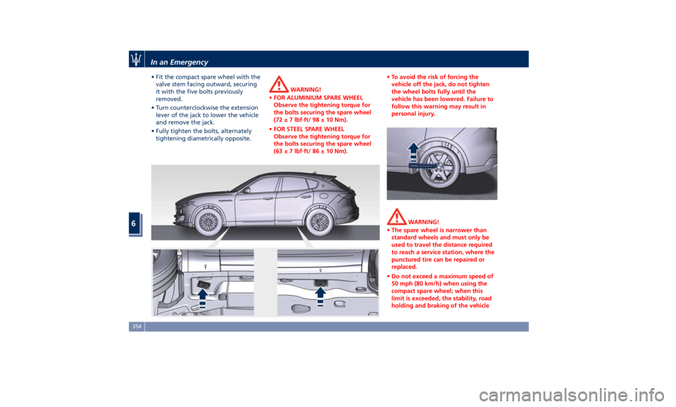
• Fit the compact spare wheel with the
valve stem facing outward, securing
it with the five bolts previously
removed.
• Turn counterclockwise the extension
lever of the jack to lower the vehicle
and remove the jack.
• Fully tighten the bolts, alternately
tightening diametrically opposite. WARNING!
• FOR ALUMINIUM SPARE WHEEL
Observe the tightening torque for
the bolts securing the spare wheel
(72 ± 7 lbf·ft/ 98 ± 10 Nm).
• FOR STEEL SPARE WHEEL
Observe the tightening torque for
the bolts securing the spare wheel
(63 ± 7 lbf·ft/ 86 ± 10 Nm). • To avoid the risk of forcing the
vehicle off the jack, do not tighten
the wheel bolts fully until the
vehicle has been lowered. Failure to
follow this warning may result in
personal injury.
WARNING!
• The spare wheel is narrower than
standard wheels and must only be
used to travel the distance required
to reach a service station, where the
punctured tire can be repaired or
replaced.
• Do not exceed a maximum speed of
50 mph (80 km/h) when using the
compact spare wheel; when this
limit is exceeded, the stability, road
holding and braking of the vehicleIn an Emergency
6
354
Page 359 of 436
will be compromised. Avoid
accelerating to full speed, heavy
braking and fast cornering.
• The compact spare wheel must be
inflated to the recommended tire
pressure (see “Tire Inflation
Pressure” in section “Features and
Specifications”).
• For safety reasons, it is absolutely
forbidden to drive with more than
one compact spare wheel fitted on
the vehicle.
• Snow chains cannot be fitted on the
compact spare wheel.
• The spare wheel can travel a
maximum of 1,800 mi (3.000 km).
To Refit the Standard Wheel with
Repair
ed or Replaced Tire
• Following the procedure and the
caution described above, raise the
vehicle and remove the compact
spare wheel reusing the supplied
wrench with adapter, suitably
extended.
• Fit the standard wheel with repaired
or replaced tire.
• Tighten the original bolts on the
wheel.
• Lower the vehicle and remove the
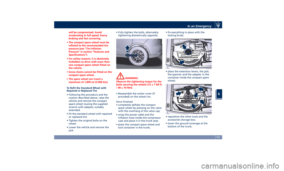
jack. • Fully tighten the bolts, alternately
tightening diametrically opposite.
WARNING!
Observe the tightening torque for the
bolts securing the wheels (72 ± 7 lbf·ft
/ 98 ± 10 Nm).
• Reassemble the center cover (if
provided)
on the wheel
rim.
Once finished:
• completely deflate the compact
spare wheel by pressing on the valve
with the overhang of the valve cap;
• wrap the power cable and the
inflation hose inside the compressor
case and place it in the trunk seat;
• place the compact spare wheel and
tool container in the trunk; • fix everything in place with the
locking knob;
• place the extension levers, the jack,
the spanner and the adapter in the
container inside the compact spare
wheel;
• reposition the other tools and the
accessories storage box;
• lower the ground coverage at the
bottom of the trunk.In an Emergency
6
355
Page 360 of 436
Emergency Release of the
Parking Brake In the event the electric parking brake
locks due to a system failure (see
“Parking Brake” in section “Driving”),
it is not possible to move the vehicle,
since the actuator that operates on the
brake pad inside each rear caliper will
lock the rear wheels.
After verifying that the battery is
sufficiently charged (otherwise use an
external power source connected to
the vehicle electric system to operate
the EPB control lever and try to unlock
the parking brake), for moving the
vehicle it is necessary to force the
actuator to release the rear brake
discs. Contact the Authorized Maserati
Dealer to carry out this operation.
WARNING!
If the parking brake has been
activated in manual or automatic
mode and it is not possible to release
it by operating on the lever of the
central console, do not move the
vehicle since rear brake calipers might
be damaged. For more information on vehicle towing see "Towing a Disabled
Vehicle" chapter in this section.
Transmission Manual
Release of P (Park)
Position The manual disengagement of the
shift from P (Park) has the purpose to
allow towing the vehicle if not
normally possible using the shift lever
(such as inability to start the engine).
This procedure is exclusively intended
for emergency situations, only!
WARNING!
Always secure your vehicle by fully
applying the parking brake, before
activating the manual park release.
Activating the manual park release
could allow your vehicle to roll away
if it is not secured by the parking
brake. Activating the manual park
release on an unsecured vehicle could
lead to serious injury or death for
those in or around the vehicle.
The cover that allows the emergency
manual
park release is
located on the
left part of the driver’s foot well.
• Lift the mat on the driver side to
access the cover.
• Slip the cover from its seat.In an Emergency
6
356