MAZDA 232 1990 Workshop Manual Suplement
Manufacturer: MAZDA, Model Year: 1990, Model line: 232, Model: MAZDA 232 1990Pages: 677, PDF Size: 61.19 MB
Page 181 of 677

F2 CUNTRULSYSTEM
‘erminal Input Output i Connected to Test condition Correct voltage Remark
2A - - ’ Ground {Injector)
Constant OV -
2B - - I Ground (Output)
Constant OV -
2c , - - 1 Ground (CPU)
Constant OV - 20
-i- Ground (Input) Constant
OV -
2E ’ 0 1 Distributor I
Ignition switch ON Approx. OV
(Ne-signal)
or 5v -
Idle Approx. 2V
2F -j- - - - -
2G 0
Distributor ignition switch ON Approx. OV
(G-stgnal) or 5V
Idle Approx. I.3
2t-I - - -
- - -
21 - - - - - -
2J C
Knock control unit
Idle Approx. 4. OV -
2K 0
Thronle sensor/ Constant . 4.5--5.W
Airflow meter
-
2L
- -
- - - -
I
2M 0 Throttle sensor
Accelerator pedal released Approx. 0.W
-
Accelerator pedal fully depressed Approx. 4.W
2N 0
20 0
2P 0
1
2Q ! 0
2R Oxygen sensor
Airflow meter
Intake air
thermosensor
Water
thermosensor 0
’ Turbocharge
indicator Ignition switch ON
f OV
Idle (Cold engine) ov
Idle (After warm-up) O-l .ov -
Increasing engine speed [After warm-up) 0.5-I .ov
Deceleration o-0.4v
ignition switch ON
’ Idle Approx. 3.8V
-
Approx. 3.OV
Ambient air temperature 20°C (68OF) Approx. 2SV In airflow meter
Engine coolant temperature 20°C (68OF) Approx. 2.5V
-
After warm-up
Below 03
Ignition switch ON
Approx. f2V
-
F2-64
Page 182 of 677

CUNTRUL SYSTEM F2
Incorrect voltage Possible cause
I
Above Ok’ l Poor contact at ground terminal l Open crrcurt in wiring from ECU to ground
Always approx. OV or approx. 2V
l Refer to Code No.02 Troubleshooting -
Always approx. OV or approx. ISV - l Refer to Code No.03 Troubleshooting
Always OV
Always OV -
- -
-
l Refer to Code No.05 Troubleshooting
l . Short circutt in wiring from ECU termrnal 2K to throttle sensor, or airflow
meter
l Poor connection at ECU connector l ECU malfunctron
Below 4-W or above 5.5V
Always OV
l ECU malfunction
l Throttle sensor malfunction l Short circurt in wiring from ECU terminal 2L to throttle sensor l Poor connection at ECU connector
l ECU malfunction
Always approx. 5V
Always constant
Always above f V
OV after warm-up
Always approx. IV after warm-up . Throttle sensor m&adjustment
l Open circuit in wiring from ECU terminal 2L to throttle sensor l Open circuit in wiring from ECU terminal 2t to ECU terminal 20
l Open circuit in wiring from ECU terminal 2M to throttle sensor l Open circuit in wiring from ECU terminal 2K to throttle sensor l Open circuit in wiring from ECU terminal 2D to throttle sensor
l Throttle sensor m&adjustment
l Refer to Code No.15 Troubleshooting
l Refer to Code No.1 7 TroubleshootIng
Always OV or approx. 5V l Refer to Code No.08 Troubleshooting
-
Always OV or approx. 5V
Always OV or approx. 5V
l Refer to Code No.1 0 Troubleshootrng
1
l Refer to Code No.09 Troubfeshooting
Always OV . Indicator broken
l Open or short circuit rn wirinq from ECU 2R to rgnition swatch
F2-65
Page 183 of 677

F2 CONTROLSYSTEM
Terminal I Input Output Connected to Test condition Correct voltage Remark
25 0
Overboost warning lgnltion switch ON Approx. 12V
-
buzzer
2T 0 1 Solenoid valve 180 seconds atter engine started when Below 1 SV
(Pressure regulator) engine coolant temperature above 90%
(I 94OF) and Intake air temperature above -
58OC (13WF)
1 Other condition at Idle Approx. 12V
2u 0 Injector (Nos. I 1 3) Ignrtion switch ON Approx. 12V * Engine Signal
Idle Approx. 12V’ Monitor: Green
and red lamps
Engrne speed above 2,000 rpm on de- Approx. f2V
flash
celeratlon (Atter warm-up)
2v 0 Injector (Nos. 2, 4) lgnitlon swrtch ON Approx. 12V
Idle Approx. 12V’
Engine speed above 2,000 rpm on de- Approx. 12V
ceieration (After warm-up)
2W 0
ISC valve Ignition switch ON Approx. 7V
-
Idle Approx. 9V
2x 0 Solenoid valve Ignition switch ON Approx. 12V
(Purge control)
t Idle -
Approx. f2V
t
2Y 0 Cmxit opening Ignition switch UN Approx. 12V
-
relay
Idle Below 1 .OV
22 - - - - - -
-L J
u-
v I U-1 l-
2y 2w 2u 2s 20 20 2M 2K 21 2G 2E 2C
2A 1U 1S IQ 10 1M 1K 11 1G 1E IC 1A
22 2X 2V 2T 2R 2P 2N 2L 2.J i’t-( 2F 2D 2B 1V 1T 1R tP IN IL I..! ItI IF
tD 18
F2-66
Page 184 of 677

CONTROLSYSTEM F2
I
7
Incorrect voltage Possible cause
Always OV l Open or short circuit in wjring from ECU terminal 2s to buzzer
Always OV or approx. 12V
1 l Refer to Code No.25 Troubieshootlng
Always OV
1
l Marn relav (FUEL INJ relay) malfunction
/ l Open or shbrt circuit in wi&g from injector to ECU terminal 2U or 2V
Always approx. 12V
l ECU malfunctron
Always OV or approx. t2V
l Refer to Code No.34 TroubleshootIng
Always OV or approx. 12V
l Refer to Code No.26 Troubleshooting
Always OV
l Open or short circuit KI wiring from ECU terminal 2Y to relay
f2-67
Page 185 of 677
![MAZDA 232 1990 Workshop Manual Suplement F2 CONTROL SYSTEM
93GOF2-79; 2
93GOF2-793
93GOFZ794
1
OXYGEN SENSOR [BP TURBO]
Inspection
Sensor
1. Warm up the engine to normal operating temperature.
2. Disconnect the oxygen sensor connect MAZDA 232 1990 Workshop Manual Suplement F2 CONTROL SYSTEM
93GOF2-79; 2
93GOF2-793
93GOFZ794
1
OXYGEN SENSOR [BP TURBO]
Inspection
Sensor
1. Warm up the engine to normal operating temperature.
2. Disconnect the oxygen sensor connect](/img/28/57056/w960_57056-184.png)
F2 CONTROL SYSTEM
93GOF2-79; 2
93GOF2-793
93GOFZ794
1
OXYGEN SENSOR [BP TURBO]
Inspection
Sensor
1. Warm up the engine to normal operating temperature.
2. Disconnect the oxygen sensor connector.
3. Connect a voltmeter to the oxygen sensor terminal @.
4. Run the engine at 4,500 rpm untiI the voltmeter indicates
approx. 0.7V.
5. Increase and decrease the engine speed suddenly and
measure the vottage.
Voltage
Engme speed Voltage (v-)
Decelerating o-0.4
Accelerating 0.5-l .o 6. Connect the
SSTs to the diagnosis connector.
7. Set the system selector select switch to 1 and the test switch
to 02 MONITOR.
8. Increase the engine speed to
between 2,000 and 3,000
rpm, and verify that the monitor lamp flashes for 10 seconds.
Specification:
Monitor lamp flashes more than 8 times/IO sec.
Heater 1. Disconnect the oxygen sensor connector.
2. Check resistance between oxygen sensor connector ter-
minals @ and 0.
Resistance: Approx.-6& [at 20°C (68OF)]
Replacement 1. Disconnect the oxygen connector. ’
2. Remove the oxygen sensor.
3. Install the new oxygen sensor and new washer.
4. Tighten the oxygen sensor to specified torque.
Tightening torque:
29-49 N-m (3-5 m-kg, 22-36 ft-tb)
Page 186 of 677

CONTROLSYSTEM F2
KNOCK SENSOR
!, -
l The knock sensor and knock control unit cannot be
inspected
individually.
When
a malfunction code number 05 is indicated,
replace.
Replacement
I_ Disconnect the knock sensor connector.
2. Raise the vehicle and support it WI safety stands.
1 93GOF2-797 3. Remove the knock sensor with using the SST
4. Install it in the reverse order of removal.
Tightening torque:
20-34 Nm (2.0-3.5 m-kg, 14-25 ft-lb)
F2-69
Page 187 of 677

Page 188 of 677

G
ENGINE ELECTRICAL SYSTEM
INDEX . ..I 1.. . . . . . . . . . . . . . . . . . . . . . . ..*. . . ..I..... . . . . . ..I...
G- 2
j FEATURES 1
OUTLINE . . . . . . . . . ...*....* .I.............. .I . . . . . . . . . . . . . .
G- 3
OUTLINE. OF CONSTRUCTION ..I... . . . . . . . . . . . G-
3
SPECtFICATiONS . . . . . . . . . . . . ..I............... . . . . . .
G- 3
1 SERVICE 1
SUPPLEMENTAL SERVICE INFORMATION . . G- 4
STARTING SYSTEM
. ..I. . . . . . . . . a.. . . . . . . . . . . . . . . . . . . G- 4
STARTER
l ..I.... . . . . . . . . . . . . . . . . . . l .*.....* .I....... . . . G- 4
CHARGlNG SYSTEM
. . . . . . . . . . . . . . . . . . . . . . . . . . . . . . . . . G- 5
PREPARATION
. . . . . . . . . . . . ..I..-... . . . . l . . . . . . . . 1. . . . . G- 5
ALTERNATOR (RHD)
. . . . . . . . . . . . . . . . . . . . . . . . . . ...*. G- 5
93GOGX-701
Page 189 of 677

G INDEX
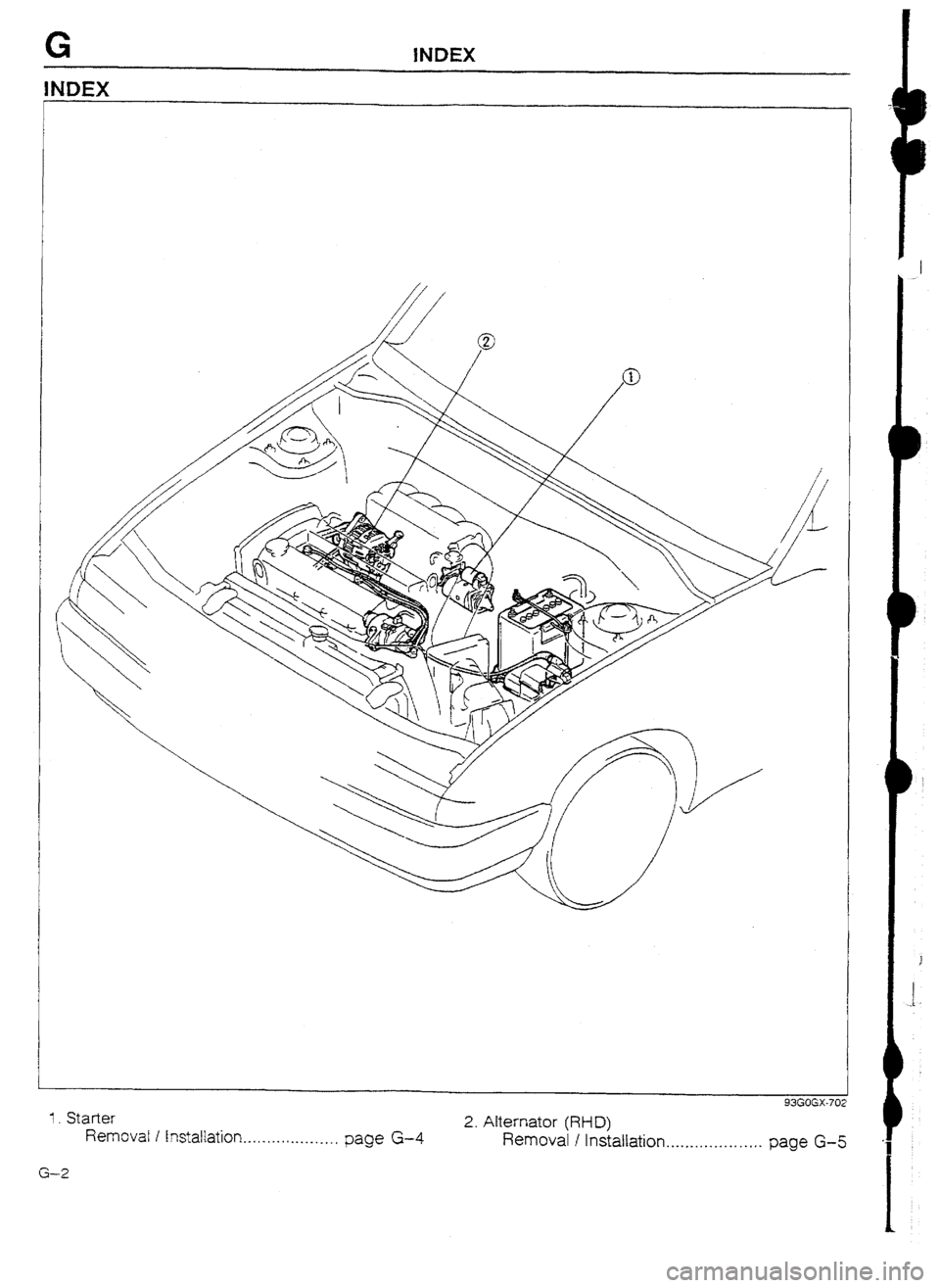
1. Starter 93GOGX-702
Removal I Instaltation... ._. . . . . . . , . . ._._, page G-4 2. Alternator (RFD)
Removal I Installation. . . .._.. . . . . . . . . . . . .
page G-5
G-2
Page 190 of 677

OUTLINE G
L
i i-
OUTLINE
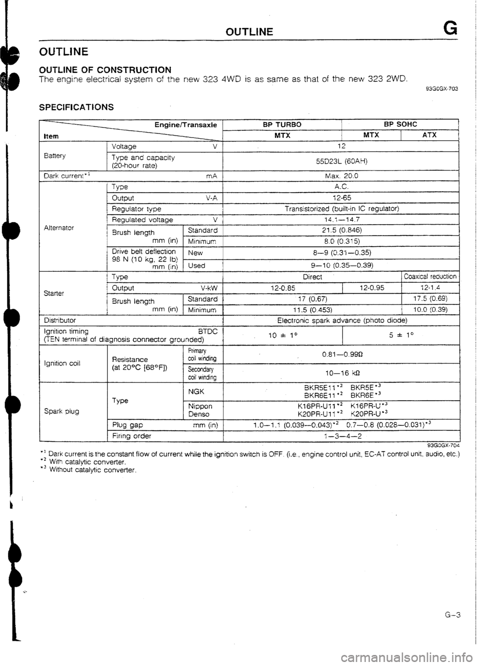
OUTLINE OF CONSTRUCTION
The engine electrical system of the new 323 4WD is as same as that of the new 323 ZWD.
93GOGX-703
SPECIFICATIONS
Item
Battery t
Voltaae EnginelTransaxle
v
Type and capacity
120-hour rate) BP TURBO
MTX BP SOHC
MTX ATX 12
55D23L (60AH)
I
Dark current” mA 1 Max. 20.0
Alternator
Output V-A 12-65
Regulator type Transistorized (built-in iC regulator)
1 I Regulated voltage v
74.1---14.7
Brush length Standard 21.5 (0.846)
mm (in)
Minrmum 8.0 (0.315)
Drive belt deflection
New
98 N (10 kg, 22 lb) 8-9 (0.31-0.35)
mm (in) Used 9-l 0 (0.35-0.39)
Type Direct ] Coaxicat reductron Starter Output V-W
12-U-85 12-0.95 32-l .4
8rush length Standard 17 (0.67) 17.5 (0.69)
mm [in) Minimum 11.5 (0.4531 10.0 (0.39) Distributor
Ignition timing
BTDC
FEN termrnal of diagnosis connector grounded) Electronic spark advance (photo
diode)
10 * I0 5 f lo
Ignition coil Resistance
(at 20°C [68OFj)
I
Primary
coil windinq
I
Spark plug Type I
Secondary 1
f coil windina 1
NGK
Nippon
Denso 10-76 kS-l
8KR5Ell +2 BKR5E”3
BKRGEI 1 l * BKRGE *3
KIGPR-Ull *2 KfGPR-I-Y3
K20PR-Ul l ** K20PR-U
l 3 0.81 ---o-999
pw am
Firrng order
I mm (in) 1.0-I .l (0.039-0.043)“2 0.7-0.8 (0.028-0.03i)*3
l-3-4-2
93GOGX-704
*I Dark current is the constant flow of current while the ignition switch is OFF. (i.e., engine control unit, EC-AT control unit, audro, etc.)
+’ With catalytic converter.
*3 Without catalytic converter.
G-3