MAZDA 232 1990 Workshop Manual Suplement
Manufacturer: MAZDA, Model Year: 1990, Model line: 232, Model: MAZDA 232 1990Pages: 677, PDF Size: 61.19 MB
Page 171 of 677

F2 FUELSYSTEM -.
03UOFX-82: 93GOF2-777
2
r
TRANSFER PUMP SWlTCH
Removal I Installation
1. Refer to replacement of the transfer pump.
(Refer to below.)
Inspection
1. Check continuity between transfer pump connector termi-
nal C and ground terminal.
r Float Dosition I Comnuity
I
I Down I Yes
I
2. If not as specified, reptace the transfer pump switch.
TRANSFER PUMP
Inspection
1. Remove the rear seat cushion.
03UOFX-823 2. Disconnect the transfer pump connector.
3. Check for continuity between transfer pump connector
terminal-wires (ES) and (t/V).
4. If no continuity exists, replace the transfer pump.
03UOFX-825
F2-54
Replacement
Warning
l When servicing the fuel system, keep sparks,
cigarettes, and open flames away from the fuel.
1. Remove the rear seat cushion.
Page 172 of 677

FUEL SYSTEM F2
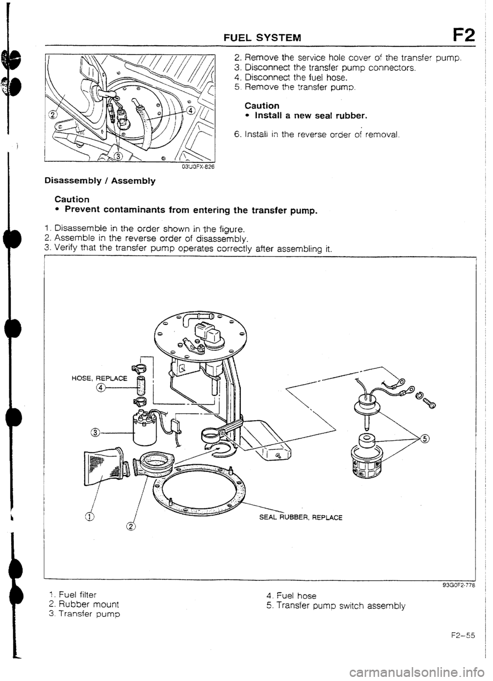
2. Remove the service hole cover of the transfer pump.
3. Disconnect the transfer pump connectors.
4. Disconnect the fuel hose,
5.
Remove the transfer pump.
6. Install in the reverse order of removal. Caution
l Install a new seat rubber.
03UOFX-826
Disassembly I Assembly
Caution
l Prevent contaminants from entering the transfer pump.
1. Disassemble in the order shown in ,the figure.
2. Assemble in the reverse order of disassembly.
3. Verify that the transfer pump operates correctly after assembling it.
HOSE, REPLACE
@
1. Fuel filter
2. Rubber mount
3. Transfer pump 4. Fuel hose
5. Transter pump switch assembly
93GOF2-77:
FZ-55
Page 173 of 677

F2 FUEL SYSTEM
93GOF2-775
1 93GOF2-78(
93GOF2-78:
1
93GOF2-78;
-
93GOF2-783
FUEL PUMP RESISTOR/RELAY
System Operation
I. Remove the rear seat cushion.
2,
Measure the voltage at the fuel pump connector terminal
A {G/O).
Voltage
r Crankinq Approx. 12V
I
I- Others t ACKXOX. I OV i
3. If not within specification, perform the following inspection,
and repair or replace if necessary.
l Fuel pump resistor/relay resistance. (Refer to below.)
l ECU II terminal voltage. (Refer to page F2-60.)
l Wiring harness and connector.
inspection
1.. Disconnect the connector.
2. Ground the fuel pump resister relay terminal D.
3. Apply 12V to terminal C and check for continuity between
terminals A and B.
Terminal C
12 applied
ov Continutty between A and B
NO
Yes
4. Measure the resistance between terminals E and F.
Resistance : 0.62-0.66Q [at 20% (68OF)l
INJECTOR
Volume Test
1. Remove the injectors with the delivery pipe.
2. Affix the injectors to the delivery pipe with wire.
Caution
l Affix the injectors firmly to the delivery pipe so that
no movement of the-injectors is possible.
Warning
l Be extremely careful when working with fuel.
Always work away from sparks or open flames.
3. Connect the SST to the battery and injector.
4. Check the injection volume with a graduated container.
Injection volume:
BP SUHC....44-47 cc (2.68-2.87 cu in)/15 sec.
BP Turbo
. ...87-105 cc (5.31 -6.41 cu in)/15 sec.
Caution
l When using the SST, make sure of the SST num-
ber and use correct one.
5. If nut correct, replace the injector(s).
Page 174 of 677

EXHAUST SYSTEM F2
EXl-iAUSTSYSTEM
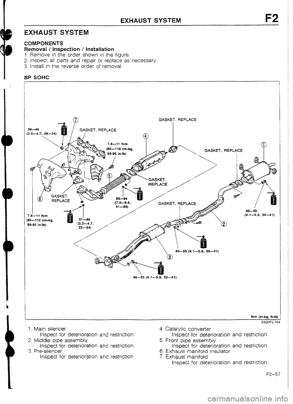
COMPONENTS
Removal ! inspection / Installation
I. Remove in the order shown in the figure.
2. Inspect alI park and repair or replace as necessary.
3. Install in
the reverse order of removal.
BP SOHC
KET, REPLACE
7.8-l-i Nm
7.8-11 N-m
{8B-110 cm-kg,
69-95 in-lb)
40-55 (4.1-5.6, 3041)
N-m (m-kg, Mb)
93GOF2-784
1. Main silencer
Inspect for deterioration and restriction
2. Middle pipe assembly
Inspect fur deterioration and restriction
3. Pre-silencer
Inspect for deterioration and restriction 4. Catalytic converter
Inspect for deterioration
and restriction
5. Front pipe assembly
Inspect for deterioration and restriction
6. Exhaust manifold insutator
7. Exhaust manifold
Inspect for deterioration and restriction
F2-57
Page 175 of 677

F2 EXHAUST SYSTEM
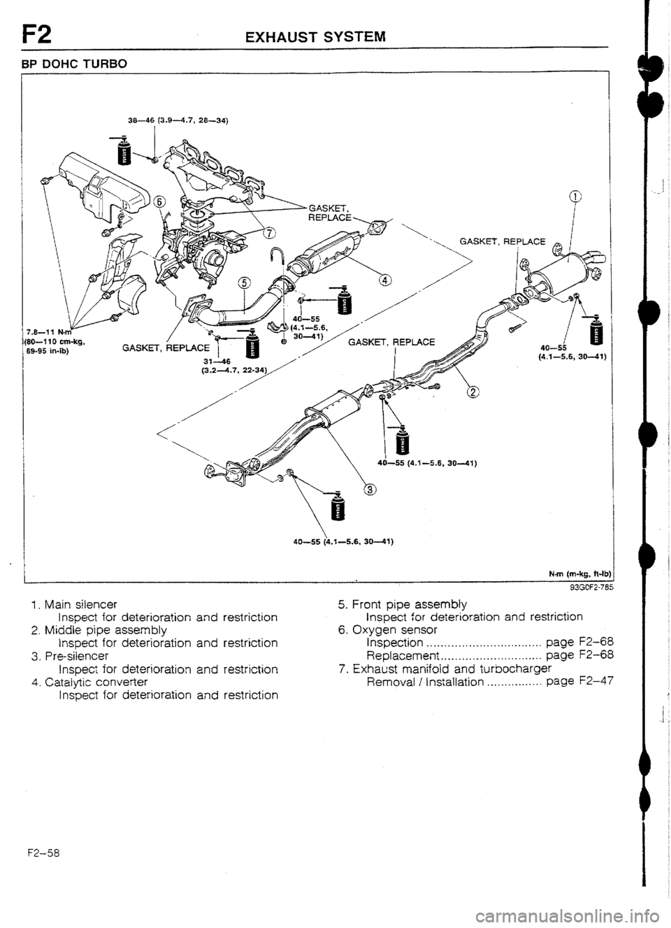
BP DOHC TURBO
38-46 (X94.7, 28-34)
I
‘ GASKET, REPLACE
40-55 (\s.‘I--5.6, 30-W)
N-m (m-kg, R-B
93GOFZ71
1 , Main silencer
Inspect for deterioration and restriction
2. Middle pipe assembly
Inspect for deterioration and restriction
3 _ P re-silencer
Inspect for deterioration and restriction
4. Catalytic converter
Inspect fur deterioration and restriction
5. Front pipe assembly
Inspect for deterioration and restriction
6. Oxygen sensur
Inspection . . . . _. . . . . . . . . _ . . . . _. . . . . . _ . . _. . page F2-68
Replac.ement . . . . . . . . . . . . . ..*.--*.-....... page F2-68
7. Exhaust manifold and turbocharger
Removal / Installation . . . . . . . . . . . . . . . . page f2-47
ET’--58
Page 176 of 677

CONTROL SYSTEM F2
CONTROLSYSTEM
PREPARATION
SST
49 HOt8 9A3
Self-dragnosls
checker
Engrne signal
IT-iOFlllO~ 49 GO18 904
Sheet System selector
I 93GUF2-786
For inspection of ECU
93GOF2-787
93GOF2-801
TERMNALS 1
--I”- -
03UOFX
ENGINE CONTROL UNIT (ECU)
Inspection
1. Disconnect the ECU connectors.
2. Connect the SSTs (Engine Signal Monitor and Adapt-
er) to the ECU as shown.
3. Place
the SST (Sheet) 011 the Engine Signal Monitor.
4. Measure the voltage at each terminal.
(Refer to pages FZ-60 to F2-67.)
5. If any ECU terminal voltage is incorrect, check the related
input or output devices and wiring. If no problem is found,
reptace the ECU. (Refer to above.)
Caution l
Never apply voltage to SST terminals A and B.
F2-59
Page 177 of 677
![MAZDA 232 1990 Workshop Manual Suplement F2 CONTROL SYSTEM
Terminal voltage [BP TURBO]
eminal input Output , 1 Connected to Test condition Correct voltage Remark
IA - - Battery Constant Approx. 12V for backup
15 0 Main relay OFF Approx. MAZDA 232 1990 Workshop Manual Suplement F2 CONTROL SYSTEM
Terminal voltage [BP TURBO]
eminal input Output , 1 Connected to Test condition Correct voltage Remark
IA - - Battery Constant Approx. 12V for backup
15 0 Main relay OFF Approx.](/img/28/57056/w960_57056-176.png)
F2 CONTROL SYSTEM
Terminal voltage [BP TURBO]
eminal input Output , 1 Connected to Test condition Correct voltage Remark
IA - - Battery Constant Approx. 12V for backup
15 0 Main relay OFF Approx. OV
(FUEL INJ relay) tgnltlon switch
-
ON Approx. 12V
1c 0 1 Ignition switch Wniie cranking Approx. 1 OV
-
(START)
lgnrtron switch ON Approx. OV
ID 0 Self -Diagnosis Test switch at “SELF-TEST” With Self-
Checker Lamp illuminated ior 3 sec. after ignition Approx. 5V Diagnosis Check-
(Monitor lamp) switch OFF* ON er and System
Lamp not illuminated after 3 sec. Approx. 12V Se’ector
Test switch at
“02 MONITOR” at idle
Monitor lamp illuminated Approx. 5V
Test switch at
“02 MONITOR” at idle
Monitor lamp not illumrnated Approx. 12’4
-lE - - - -
- -
1F 0 Self-Diagnosis Buzzer sounded for 3 sec. after ignition
Below 2.5V l With Self-
Checker switch OFF -+ ON Diagnosis
(Code Number)
Buzzer not sounded after 3 sec. Approx. 12V Checker and
Buzzer sounded Below 2.9 System Selector
l With System
Buzzer not sounded Approx. 12V Selector test
switch at
“SELF-TEST’ ’
I I 1G
0 Igniter
7H
0 Solenoid vahe
(Wastegate)
l!
0 Fuel pump
resistor/relay
I
lJ I r-Tcreiay Ignition switch ON
ld!e
Engine speed below 5,300 rpm
Engine speed above 5,300 rpm
While cranking
Idle
Ignition switch ON
AK switch ON at idle 1 Approx. OV
-
Approx. 0.2V
Approx. 12V
-
Below 1.5V
Approx. 1 OV
-
I3elow 15V
Approx. 12V
Below 2.5V
AIC switch OFF at idle Approx. 12V
-
IK 0 Diagnosis System Selector test switch at
connector
(TEN terminal)
1L - - -
- -
-
IM
t 0
1 Ground (Australia) Constant Below 1 .OV Not used
(Except Australia)
F2-60
Page 178 of 677

CONTROL SYSTEM F2
Incorrect voltage Possible cause
Always OV
l ROOM 10A fuse burned l Open circuit in wiring from ROOM 10A fuse to ECU termrnal IA
Always OV
I l Main relay maifunctlon l Open or short crrcu~t in wirrng from main relay to ECU termrnal 1 B
Always OV (Srarrer turns)
l Open or short circuit in wiring from ignition switch to ECU terminal 1C
Always UV
l Main relay (FUEL INJ relay} malfunctron l Open circuit in wiring from main relay to diagnosis connector terminal + B l Open or short circuit in wiring from dragnosls connector terminal MEN to
ECU terminal 1D
Always approx. 12V
I . Poor connection at ECU connector
l ECU matfunction
Always approx. 5V
l ECU malfunction
-
I -
Always below No disptay on Self- . Main relay (FUEL INJ retay) malfunction (Refer to page F3-142)
2.5V Diagnosis Checker l Open circuit in wiring from main relay to diagnosis connector termjnal + B
“88” displayed and
l Open or short circuit in wiring from diagnosis connector terminal FEN to
buzzer sounds con- ECU terminal 1 F
tinuously
Always approx. 12V
l Poor connection at ECU connector l ECU malfunction
Always OV
l Short circuit in wiring from igniter to ECU terminal tG
Atways OV or approx. 12V
l Refer to Code No.42 Troubleshooting (Refer to page F2-30)
Always approx. 12V
l Fuel pump resistor/relay malfunction
Always OV
l Open or short circuit in wiring from ECU terminal 1 I to resistor/retay
Always below
A/C does not operate
l AJC relay malfunction
23 l Open circuit in wiring from ignition switch to NC relay l Open circuit in wiring from A/C relay to ECU terminal IJ
A/C switch OFF but
l Short circuit in wiring from A/C relay to ECU terminal IJ
AIC operates
l ECU matfunction
Always approx. t2V
Always below 1 .OV
l Poor connection at ECU connector l ECU malfunction
l Short circurt in wiring from diagnosis connector terminal TEN to ECU termi-
nal 1K
Always approx. 12V
l Open circutt in wiring from diagnosis connector terminal TEN to ECU termi-
nal lK
l Open c~rcud in wiring from diagnosis connector terminal GND to ground
Always above 1 .OV
I
l Open circuit in wiring from ECU terminal 1 M to ground
F2-61
Page 179 of 677

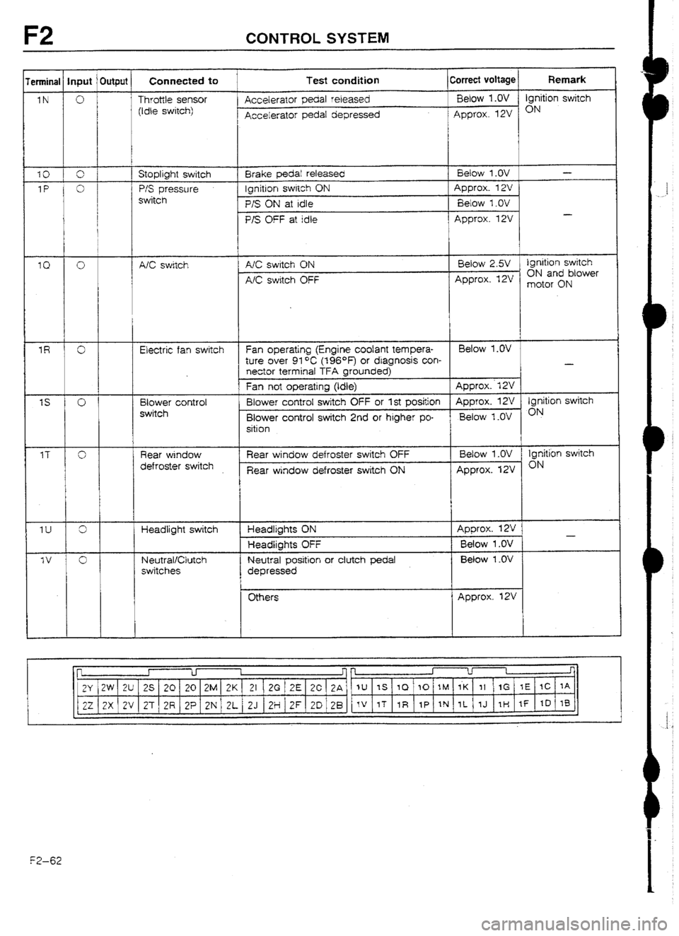
F2 CONTROLSYSTEM
erminat Input ’ Output Connected to Test condition Correct voltage Remark
1N 0 I Throttle sensor Accelerator pedal released &low l.OV j Ignition switch
(Idle switch)
Accelerator pedal depressed Approx. 12V *N
IO I 0 j [ Stoplight switch Brake pedal released Betow 1 .OV -
1P j 0 1 i P/S pressure lgnitlon switch ON Approx. 12V
I
switch
f/S ON at idle Below 1 .UV
I
P/S OFF at idle Approx. 12V -
I
to 0 A/C switch A/C switch ON
NC switch OFF Beiow 2.W ignition switch
ON and blower
Approx* t2V motor ON
i
1R 0 Electric fan switch Fan operating (Engine coolant tempera- Betow l.OV
ture over 91 *C (t96*F) or diagnosis con-
-
nector terminal TFA grounded)
Fan not operating (Idle) Approx.. f 2V
IS 0 Blower control Blower controf switch OFF or 1st position Approx. 13 Ignition switch
switch
Blower control switch 2nd or higher po- Below 7 .OV ON
sition
IT
Cl Rear window
defroster switch Rear window defroster switch OFF
Rear window defroster switch ON Below 1 .OV Ignition switch
Approx. 12V ON
1u 3 Headlight switch Headlights ON Approx. 12V
-
Headlights OFF Below 1 .OV
-Iv Cl ’ Neutral/Clutch
Neutral position or clutch pedal Below I .OV
switches
depressed
Others Approx. 12V
l-7 I r
f
2V 2W 2U 25 20 20 2M 2K 21 2G IZE 2C 2A IU IS 10 10 IM 1K 11 1G rE tC IA
22 2X (2V 2T 2R 2P 2N 2L 2J 2H’ZF 20 2B fV 1T 1R IP IN 1L 7J III If ItI 1B l F2-62
Page 180 of 677

CONTROL SYSTEM F2
Incorrect voltage
Always below 1 .OV Possible cause
l Throttle sensor misadjustment l Short circuit in wiring from throttle sensor to ECU terminal IN l ECU malfunction
Always approx. f 2V
Atways below 1 .OV (Stopfights OK)
Always below 1 .OV
l Throttle sensor misadjustment l Open circuit in wiring from throttle sensor to ECU terminal IN l Open ctrcuit in wiring from throttle sensor to ECU terminal 20
l Open crrcurt in wiring from stoplight switch to ECU terminal 10
l P/S pressure switch malfunction l Short circuit in wirrng from P/S pressure switch to ECU termrnai 1 P
l ECU malfunction
Always approx. 12V
Atways below 2.5V (Btower fan OK) . P/S pressure switch malfunction
l Open circuit in wiring from P/S pressure switch to ECU terminal I P l Open circuit in wiring from P/S pressure switch to ground
l A/C switch malfunction l Short circuit in wiring from A/C switch to ECU terminal 1 Q l Poor connection at ECU connector l ECU malfunction
Always approx. 12V (Blower fan OK)
l ’ A/C switch malfunction l Open c~rcurt in wiring from NC switch to ECU terminal 1Q l ken circuit H-I winnu from A/C switch to blower control switch
Always below 1.W
l Open or short circuit in wiring from fan relay to ECU terminal IR
(Electrkal cooling fan UK} l ECU malfunctron
Always below 1 .OV (Blower fan OK)
l Short crrcutt in wiring from blower control swrfch to ECU terminal IS l Poor connection at ECU connector l ECU malfunction
Always approx. 12V (Blower fan OK)
Always below Illumination lamp
1.w ON when rear
window defroster
switch ON 1
l Open circurt in wrring from blower control switch to ECU terminat IS
I
l Open or short circuit rn wiring from rear window defroster switch to ECU
terminal 1 T
ftlumination lamp
never ON
l Open circuit in wiring from ignition switch to rear window defroster switch
l Rear window defroster switch malfunction I
Always below 1 .OV (Headlights OK)
l Open or short circurt in wiring from headlight relay to ECU termtnal 1 U
Always below 1 .OV
Always approx. l2V
l Neutral switch malfunction l Clutch switch malfunction l Short circuit in wiring from ECU terminal IV to neutral or clutch switch
l Neutral switch maifunctton l Clutch switch malfunction l Open circuit in wiring from ECU terminal IV to neutral or clutch swttch
l Poor connection at ECU connector
93GOFZ789
F2-63