MAZDA 323 1992 Suplement Owner's Manual
Manufacturer: MAZDA, Model Year: 1992, Model line: 323, Model: MAZDA 323 1992Pages: 279, PDF Size: 24.15 MB
Page 21 of 279
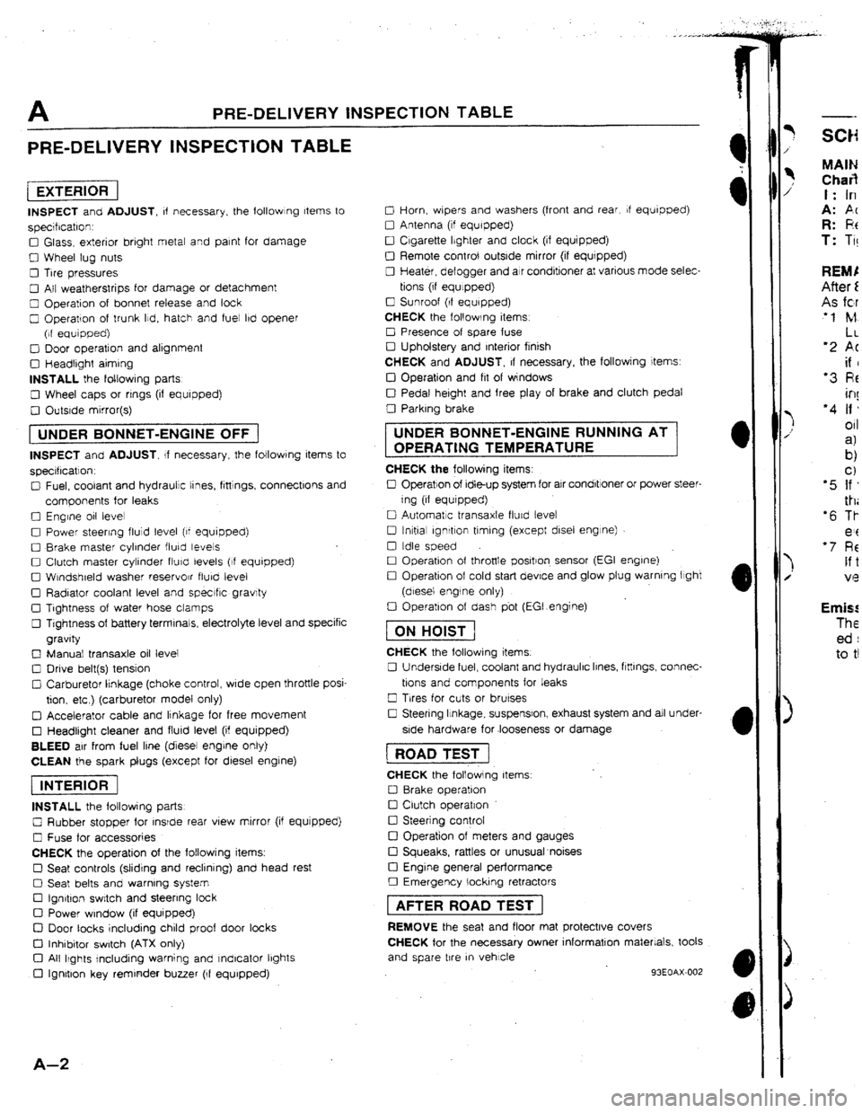
A PRE-DELIVERY INSPECTION TABLE
PRE-DELIVERY INSPECTION TABLE
[EXTERlORI
INSPECT and ADJUST, of necessary. the followlng Items to
specrfrcatron:
0 Glass, exterior bright metal and paint for damage
0 Wheel lug nuts
0 Tire pressures
0 All weatherstrips for damage or detachment
0 Operation of bonnet release and look
0 Operation of trunk Ild, hatch and fuel lbd opener
(of equipped)
0 Door operation and alignment
0 Headtrght aiming
INSTALL the foltowrng parts
0 Wheel caps or rrngs (if equipped)
0 Outsrde mirror(s)
1 UNDER BONNET-ENGINE OFF j
INSPECT and ADJUST. If necessary, the following items to
specrflcatlon.
0 Fuel, coolant and hydraulic tines, fittings, connectlons and
components for leaks
0 Engine 011 level
0 Power steering fluid level (of equipped)
0 Brake master cylinder fluky levels
0 Clutch master cylinder fturcl levels (If equipped)
0 Wtndshreld washer reservojr flurd level
0 Radiator coolant level and specrfic gravity
0 Tightness of water hose clamps
0 Tightness of battery terminals, electrolyte level and specific
gravity
0 Manual transaxle oil level
0 Drive belt(s) tension
Cl Carburetor lrnkage (choke control, wrde open throttle posi-
tion. etc ) (carburetor model only)
q Accelerator cable and linkage for free movement
0 Headlight cleaner and flurd level (if equipped)
BLEED air from fuel line (diesel engrne only)
CLEAN the spark plugs (except for diesel engine)
piEi6F]
INSTALL the following parts
0 Rubber stopper for rnsrde rear view mirror (if equjpped)
0 Fuse for accessories
CHECK the operation of the following items.
0 Seat controls (sliding and reclining) and head rest
0 Seat belts and warning system
Cl Ign&on switch and steering lock
0 Power window (if equipped)
D Door tacks including child proof door locks
Cl Inhibitor switch (ATX only)
Cl All Ikghts rncluding warning and Indicator lbghts
0 Ignition key reminder buzzer (If equipped)
A-Z
0 Horn, wbpers and washers (front and rear, If equipped)
0 Antenna (tf equipped)
0 Cigarette Ibghter and clock (if equipped)
0 Remote control outside mirror (if equrpped)
0 Heater, defogger and air conditioner at various mode selec-
tions (if equlppedj
0 Sunroof (If equipped)
CHECK the following items
0 Presence of spare fuse
0 Upholstery and Interior finish
CHECK and ADJUST, If necessary, the followjng items:
IJ Operation and fit of windows
0 Pedal height and free play of brake and clutch pedal
0 Parking brake UNDER BONNET-ENGINE RUNNING AT
OPERATING TEMPERATURE
CHECK the following items:
0 Operation of Idle-up system for air condbtroner or power steer-
ing (if equrpped)
0 Automatic transaxle flurd levet
0 tnltial ignrtlon timing (except disel engine)
0 Idle speed
0 Operation of throttle positron. sensor (EGI engrne)
0 Operation of cold start device and glow plug warning light
(diesel engine only)
0 Operation of dash pbt (EGI.engine)
fTiGGJ
CHECK the following items.
0 Underside fuel, coolant and hydraulic Irnes, ftttlngs, connec-
tions and components for leaks
0 Trres for cuts or brurses
0 Steering Itnkage, suspensron, exhaust system and all under-
side hardware for .looseness or damage 1 ROAD TEST j
CHECK the following items
0 8rake operation
0 Clutch operation
0 Steering control
!ZI Operation of meters and gauges
Cl Squeaks, rattles or unusual noises
Cl Engine general performance
0 Emergency locking retractors 1 AFTER ROAD TEST ]
REMOVE the seat and floor mat protective covers
CHECK for the necessary owner information materials, took
and spare tire
m vehicle
93EOAX-002
-- MAIN Char3 t: In
A: PC R: F!t T: Ti! Emis! The ed : to t!
Page 22 of 279
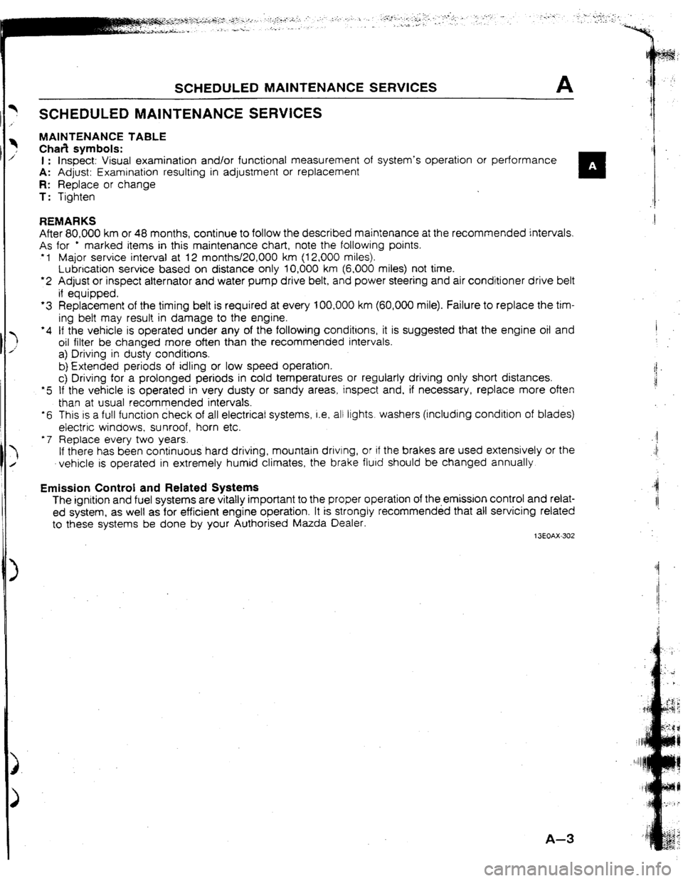
SCHEDULED MAINTENANCE SERVICES A
SCHEDULED MAINTENANCE SERVICES
MAINTENANCE TABLE
Chafi symbols:
1 : Inspect: Visual examination and/or functional measurement of system’s operation or
performance , A: Adjust: Examination resulting in adjustment or replacement
n
R: Replace or change
T: Tighten
REMARKS
After 80,000 km or 48 months, continue to follow the described maintenance at the recommended intervals.
As for * marked items in this maintenance chart, note the following points.
+ 1 Major service interval at 12 months/20,000 km (12,000 miles).
Lubrication service based on distance only 10,000 km (6,000 miles) not time.
l 2 Adjust or inspect alternator and water pump drive belt, and power steering and air conditioner drive belt
if equipped.
‘3 Replacement of the timing belt is required at every 100,000 km (60,000 mile). Failure to replace the tim-
ing bett may result in damage to the engine.
‘4 tf the vehicle is operated under any of the following conditions, it is suggested that the engine oil and
oil filter be changed more often than the recommended intervals.
a) Driving in dusty conditions. I
:
b) Extended periods of idling or low speed operation. i
i!
c) Driving for a prolonged periods in cold temperatures or regularly driving onty short distances.
*5 If the vehicle is operated in very dusty or sandy areas, inspect and, if necessary, replace more often
than at usual recommended intervals.
l 6 This IS a full function check of all electrical systems, i.e, atl
ltghts. washers (including condition of blades)
electric windows, sunroof, horn etc.
‘7 Replace every two years. $1
‘I
If there has been continuous hard driving, mountain
drivtng, or if the brakes are used extensively or the
vehicle is operated in extremely humid climates, the brake fluid should be changed annually.
Emission Control and Related Systems
The ignition and fuel systems are vitally important to the proper operation of the-emission control and relat-
ed system, as well as for efficient engine operation. It is strongly recommended that all servicing related
to these systems be done by your Authorised Mazda Dealer.
13EOAX-302 -4
I!
A-3
Page 23 of 279

A SCHEDULED MAtNTENANCE SERVtCES (Europe)
Maintenance Number of months or km (miles), whichever comes first
Months” - 6 12 18 24 30 36 42 48
Kllometers 1,000 10,000 20,000 30,000 40,000 50,000 60,000 70,000 80,000
{Miles)
(600) (6,000) f[t2,000) (18,000) (24,000) (3U,OOO) (36,000) (42,000) {48,000), Engine
Intake and exhaust manrfold nuts (Bolts)
Drive belts”
i Engine trmlng beltW3
Engine oil (Turbo)‘4
01 filter
l *
Cool!ng system (Includtng
coolant level adlustment)
Engrne coolant T T T
A A A
A A
Replace every 100,000 km (60,000 miles)
Replace every 5,000 km (3,000 miles) or 6 months
R R R R R 1 R R R
I I I I
I
Replace every 2 years Fuel system
Idle speed
Air cleaner element * 5
Fuel
falter
Fuel Ilnes and hoses Ignition system
A f 1
I R I R
R R
I I f t I ~
lnlttal rgnrtloh trmlng 1 I I I I I I I I
Spark plugs A
A. A A
Spark plugs (Only for Sweden) Adjust every 30.000 km (t8.000 mrls) Evaporative emission control system
Throttle sensor Throttle sensor (Only for Sweden)
Evaporative system
Evaporatrve system (Only for Sweden) 1 A 1 1 A 1 1 A 1 ) A
Adjust every 80,000 km (48,000 miles)
1 I 1 1 I’ 1 1 I 1 1 I
Inspect every 80,000 km (48,000 mites) Electrical system
Battery electrolyte level and specific gravity 1 I f I I I
All Electrical system
l ’ 1 I
I 1 I I I
1 . 1 I I
Headlight alrgnment 1 A A A . A. Chassis and body
t 3EOAX-303
A-4 Chas
SW31 Rear
Tires
Hing
Seat
Page 24 of 279
![MAZDA 323 1992 Suplement Owners Manual SCHEDULED MAINTENANCE SERVICES (Europe) A
Maintenance Number of months or km (miles), whichever comes first
Months’ ’
- 6 12 18 1 24 30 36 ] 42 48
Kllometers 1,000
10,000 20,000 30,000 1 40,0 MAZDA 323 1992 Suplement Owners Manual SCHEDULED MAINTENANCE SERVICES (Europe) A
Maintenance Number of months or km (miles), whichever comes first
Months’ ’
- 6 12 18 1 24 30 36 ] 42 48
Kllometers 1,000
10,000 20,000 30,000 1 40,0](/img/28/57055/w960_57055-23.png)
SCHEDULED MAINTENANCE SERVICES (Europe) A
Maintenance Number of months or km (miles), whichever comes first
Months’ ’
- 6 12 18 1 24 30 36 ] 42 48
Kllometers 1,000
10,000 20,000 30,000 1 40,000 50,000 60,000 1 70,000
80,000
(Miles) (600)
(6,000) j(12,000)~(18,000)~(24,000) (30,000) (36,000)~(42,000) (48,000)
Chassis and body (Cont’d)
Steering and front suspension
I ’ I
I 1 I
MTX oil A R
Rear axle oil
I R A A R
A A A R I
Trabsfercarrier oil R A 1 A
R A A A R
Bolts, nuts on chassis and body T T 1
T , T T
Body condltlon (Visual only) Inspect annually
Exhaust system heat shields I 1 I
Tires (Including spare tjresj with inflation
pressure adjustment I
I I I
Hinges and catches A A
A 1 A
Underside of vehicle I
I i 1 I I
Seat belt I
I f
I ’ I
Dnveshafl dust boots I I 1 I I
13EOAX.304
A-5
Page 25 of 279

B2
ENGINE
(DOHC)
1 FEATURES j
OUTLINE ................................................
B2- 2
OUTLINE OF CONSTRUCTION..
.............. B2- 2
SPEClFICATlONS
..................................
82- 2
INTERCHANGEABILITY ..........................
B2- 3
PISTON ...............................................
82- 4
CONNECTING ROD ...............................
82- 5
CRANKSHAFT PULLEY ..........................
B2- 6
EXHAUST VALVE ..................................
B2- 7
INSTRUCTION FOR HANDLING METALLIC
SODllJM~FlLLED EXHAUST VALVE .........
82- 8
SUPPLEMENTAL SERVICE INFORMATION 820 9
4
13E082-301
Page 26 of 279
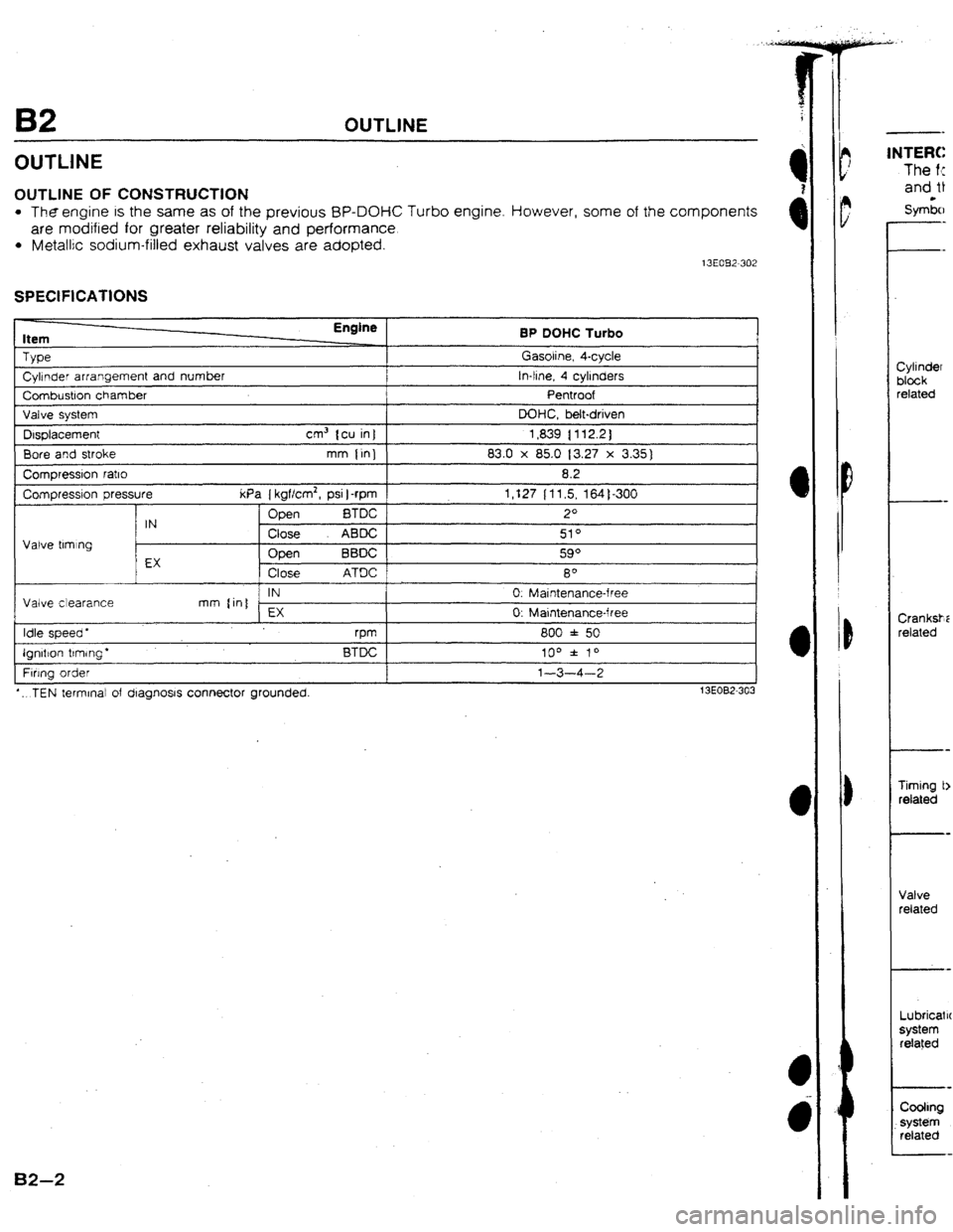
B2 OUTLINE
OUTLINE
OUTLINE OF CONSTRUCTION
l Theengine is the same as of the previous BP-DOHC Turbo engine. However, some of the components
are modified for greater reliability and performance.
l Metallic sodium-filled exhaust valves are adopted. 13E032-302
SPECtFlCATIONS
Item
TYPe
Cyhnder arrangement and number
Combustion chamber
Valve system
Displacement cm3 tcu in]
Bore and stroke mm {in)
Compressron ratio
Compressron pressure kPa [ kgf/cm2, psi 1
-rpm
Open
BTDC
IN
Close ABDC
Valve tlmlng
EX Open BBDC
Close ATDC
IN
Valve clearance mm (in]
EX
Idle speed *
rpm
Ignltlon trmrng’ BTDC
Fwng order
*.. TEN terminal of dragnosrs connector grounded. Gasoline, 4-cycle
tn-line, 4 cyljnders
Pentroof
DOHC, belt-driven
1,839 { 112.2)
83.0 x 85.0 13.27 x 3.35)
8.2
1,127 lt1.5, 164)-300
2O
510
590
8O
0. Maintenance-free
0: Maintenance-free
800 f 50
100 f 70
l-3-4-2
13EOB2-303
82-2
1NTERC
The f<
and 0
S ym&l
-
Cytinder
block
related
Crank&;
related
Timing b
related
Vatve
related
Lubricatrc
system related
Coohng
. . system
related
Page 27 of 279

The following chart shows interchangeability of the main parts of the previous BP DOHC Turbo engine
and the new BP DOHC Turbo engine for 4WD models.
S ymiols: 0 _. lnterc hangeable X . . . Not Interchangeable
Part name tnterchangeability
Remark
Cytlnder head 0
Camshaft 011 seal 0
Cvllnder head bolt 0
CB :
Cyh nder
blcck
related
Crankshaft
related
Timing belt
related
Valve
related
Lubrication
system
related Cylrnder head gasket 0
Wnder head cover 0
Cylinder head cover gasket
Cylinder block
MaEn bearina cao 0
0
0
Ma+n bearino suo~oFt elate I
0 I ” ,I I
Oil pan
Timrno belt cover I X
0 I
Turbocharger oil return pipe hole increased from
13mm IO.51 in) to 17mm IO.67 in)
Seal elate
Front orl seal I 0 I
I I 0
1
Rear 011 seal 0
Crankshaft 0
Marn bearina 0
Thrust bearing
Connectmg rod
Connecting rod beartng
Piston 0
;J
X
Shape different
Piston skirt shortened
I Piston pm cl
Tw
X Sectional shape different
Piston rrng Piston ring end gap increased from 0:?5--0.30mm
Second
X ~0.006-0.011 in ) to 0.35-0.50mm IO.01 4-0.019
in ] (Measured In cylinder)
Crankshaft pulley Shape different
Rear cover ;5
Flywheel
I 0
Flywheel bolt 0
Tbmlng belt 0
Timing belt crank pulley 0
Camshaft pulley 0
Timing belt tensioner and spring
0
Idler 0
Camshaft 0
AA
Valve Intake
Exhaust
cl
0
X Metallic sodium-filled valve
Valve spring Intake
I 0
and seat
Exhaust 0
Vatve wide I 0
Valve seal
Oil pump 0
Oil pump gasket 0
oil strainer 0
Oil strainer gasket 0
Oil cooler
X Heat dissi patlon capacity increased
Oil jet
Oil filter Shape different
1 Water pump 0
Coohng Thermostat 0
system
related Radiator 0
Cooling fan 0
I 3EO32.304
BZ-3.
Page 28 of 279
![MAZDA 323 1992 Suplement Owners Manual B2 OUTl1NE
COOUNG CHANNEL RtNG CARRtER
61.5mm i 2.42 in ] - 56.5mm (2.22 in
Piston diameter Piston diameter
Measured at 90* Measured at 90°
to pin bore axis I+ to pin bore axis
and t6.5mm and 1 MAZDA 323 1992 Suplement Owners Manual B2 OUTl1NE
COOUNG CHANNEL RtNG CARRtER
61.5mm i 2.42 in ] - 56.5mm (2.22 in
Piston diameter Piston diameter
Measured at 90* Measured at 90°
to pin bore axis I+ to pin bore axis
and t6.5mm and 1](/img/28/57055/w960_57055-27.png)
B2 OUTl1NE
COOUNG CHANNEL RtNG CARRtER
61.5mm i 2.42 in ] - 56.5mm (2.22 in
Piston diameter Piston diameter
Measured at 90* Measured at 90°
to pin bore axis I+ to pin bore axis
and t6.5mm and 11 .Omm
IO.650 in 1 below 10.433 in 1 below
oil rmg groove. oil ring groove.
COOLING CHANNEL
*IL YTLET
OIL t NiET
l The piston skirt is shortened for reduced weight and friction. l A cast iron ring carrier is installed in the piston to reduce piston-ring groove wear. l A cooling channel is incorporated in the body of the piston. The 011 jet squirts oil into this cootrng channel
and the or! absorbs
the heat from around the ring lands, reducing piston ring and cylinder wat! wear
Bz-4
Page 29 of 279
OUTLINE B2
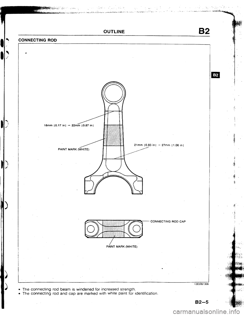
CONNECTING ROD
18mm 10.17 in!
PAINT
MARK @VHITE) in t - 27mm Il.06 ml
CONNECTING ROD CAP
PiINT MARK (WHITE)
l The connecting rod beam is windened for increased strength.
l The connecting rod and cap are marked with white paint for identification.
Page 30 of 279
B2 CXJTUNE
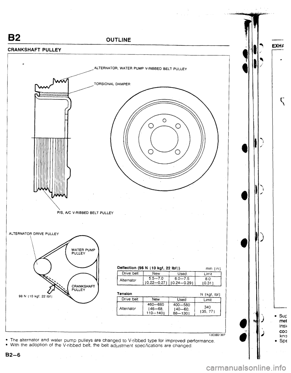
CRANKSHAFT PULLEY
ALTERNATOR, WATER PUMP V-RIBBED BELT PULLEY
/TORSIONAL DAMPER
P/S, A/C V-RI3BED BELT PULLEY
ALTERNATOR DRIVE PULLEY
Deflectton (98 N ( 10 kgf, 22 Ibf f ) mm ftn)
Owe belt New Used. Lrmlt
Alternator 5.5-7.0 6.0-7.5 8.0
{0.22-0.27 ) IO.24-0.29) to.31 )
fension
Owe belt
Alternator New
460-660
(46-68,
llO--140) Used
400-580
{‘IO-60,
88-130 1 N I kgf, Ibf]
Ltmit
340
135, 771
l The alternator and water pump pulleys are changed to V-ribbed type for improved performance l With the adoptjon of the V-ribbed betf. the belt adjustment specifications are changed.
B2-6