MAZDA 323 1992 Suplement User Guide
Manufacturer: MAZDA, Model Year: 1992, Model line: 323, Model: MAZDA 323 1992Pages: 279, PDF Size: 24.15 MB
Page 11 of 279

. _ .
GI JACK AND SAFETY STAND POSlTiOtWVEHlCLE LIFT (2-SUPPORT TYPE) POSlTlONS
JACK AND SAFETY STAND POSITIONS
FRONT END
JacKposition:
At the front crossmember Safety stand positions:
On both sides of the body frame
REAR END
Jack position:
At the center of the rear crossmember Safety stand positions:
On both sides of the body frame
At the rear differential (4WD)
--
03UGW80
VEHICLE LIFT (2-SUPPORT TYPE) POSITIONS
FRONT END, REAR END
Frame Frame
Side sills Side sills
9MuGIX 010 9MVGtX 01
Page 12 of 279

MAlNTENANCE NOTE GI
.
FREE ROLLER
I t 3EGlX-304
MAlNTENANCE NOTE
SPEEDOMETER TESTER CHECK
Caution
l Do not clutch abruptly.
l Do not attempt rabbit starts or accelerate quickly. 13EGIX-302
[Front wheel free-roller method]
1. Set the free roller securely on the floor under the front wheels
by matching it to the wheel base and front tread.
2. Place the vehicle softly on the tester and free roller.
3. Start the engine, and engage the clutch softly at a low speed
in 2nd gear; then gradually increase the speed.
4. Upon completion of the test, stop the engine by gradually
decelerating with soft braking.
[Front wheel jack-up method1
1’. Place the rear wheels on the roller.
2. Jack up the front wheels and mount on a safety stand.
3. Start the engine, and engage the clutch softly at a low speed
in 2nd gear; then gradually increase the speed.
Caution
l When using either the front wheel free-roller meth-
od or front wheel jack-up method, secure the vehi-
cle to prevent forward and lateral movement by
attaching towing hardware (chain or wire) to the
front and rear tow hook or tie-down hook.
BRAKE TESTER CHECK
Caution
. To stabilize the drag force of the viscous coupling,
conduct the brake test after the speedometer test.
1. Place the wheels to be tested (front or rear) on the roller.
2. Shift itit0 NEUTRAL.
3. Drive the tester roller and check.
a-9
Page 13 of 279

GI MAINTENANCE NOTE
VIEWED
.OM BELOW
‘REE
13EGfX-307
I
I t3EGIX-308 CHASSIS DYNAMOMETER CHECK
Caution
l Do not clutch abruptly. l Do not attempt rabbit starts or accelerate quickly.
1. Remove the propeller shaft.
2. Lock the center differential (2WD).
3. Place the front wheets on the roller.
4. Lock the rear wheels and apply the parking brake.
5. Drive the tester roller and check.
6. Upon completion of the test, gradually decelerate with soft
braking and stop the engine.
7. When the test is done, return the differential lclck rod to the
free condition (4WD) and reinstall the propeller shaft.
WHEEL BALANCER (On-the-car Balance)
1.
Jack up all four wheels. Support the wheels to be checked
(front or rear) with the wheel balancer sensor stand and the
remainrng wheels with safety stands.
2. Set the on-the-car balancer. With the center differential in
free condition, drove the tires with the engine; then check.
Page 14 of 279

MAINTENANCE NOTE
TOWlNG
Caution
g Use method @I to tow vehicles having problems in the steering system or drivetrain.
Towing method
0 Rope towing items to confirm
Parking brake Transaxle shtft posttton Remarks
Released Neutral
@ Towlng with front wheels off
ground
Released Neutral Remove propeller shaft
@ Towtng by wrecker truck
Released Neutral
Rempve propetler shaft
@Towing or hauling with all wheels
off ground
Engaged Any posItIon
13EGIX.30
TIE-DOWN HOOKS - FRONT TIE-DOWN HOOKS
- REAR (HATCHBACK)
!
Page 15 of 279

GI IDENTIFICATION NUMBER tOCATlONS/UNlTS/ABBREVIATlONS
IDENTIFICATION NUMBER LOCATIONS
VEHICLE tDENTtRCATtUN NUM8ER (VIM) ENGINE MODEL AND NUMBER
I
UNITS
N.rn { kgf m or kgfcm,
f-t&f or tn.lbf 1 . . . . . . . . . . . . . . . . Torque
rpm ._ . . . Revolutions per minute
A.. ,_...___.... Ampere(s)
v I... Volt(s)
$2 . .._..__......_.....__... Ohm(s) (resls‘tance)
kPa { kgflcm*, psr] . . . . . . . Pressure
{usually positive)
mmHg I inl-lg ] . . . . . . . . . Pressure
(usually negatrve)
W . . . ._ .._.__ .._ . . . . . . ..,......... Watt
titers [US qt, Imp qt 1 . V&me
mm { rn 1 . . . . . . . . . . . . . . . . . . . . . . . Length
89UOGX-006
ABBREWATIONS
ABDC _. . . . . . . . . . . After bottom dead
center
A/C . . . . . . . ._.. _. . . . . . . . . Air conditioner
ACC .__ . . . . . . . Accessones
ATX .._ ._ . . . . . . . . . . . . . . Automate transaxle
ATDC _.. __ _. . . . . After top dead center
ATF ,... ._....__._.. Automatic transmission
fluid
BAC ._ . . . . . . . . . . . . . . ,. Bypass air control
BBDC _. . . . . . . . . . . . . .._. Before bottom dead
center
BTDC ., ._._... . . . Before top dead center
CPU . . . . . . . . . Central processrng unit EC-AT
........................... Electronrcally-controlled
automatic transmlsslon
ECU ._ ....................... Engine control unit
EG 1 ..................... Electronc gasoll ne
injectron
E/L. ............................ Electrrcal load
EX .............................. Exhaust
IC ................................ Integrated clrcult
IGN ........................... lgnrtlon
IN ..... ........................ Intake
INT
............................... Intermittent
ISC ............................ Idle speed control
U-l ................................
Left hand
M..
........................... Motor
MIL
........ ...................... MatfunctIon Indicator
iamp
MTX. ........................... Manual transaxle
00.. .............................. Overdnve
Of F .............................. Swrtch off
ON
............................... Switch
on
PCV .............................. Positive crankcase
ventilation
PRC .......................... Pressure regulator
control
P/S ............................. Power steerrng
P/W ............................
Power window
RH ............................... Rlght hand
SST
............................. Special service tool
ST.. ............................... Starl
SW.. ............................. Switch
TDC. ............................ Top dead center
4WD .............................
4-wheel drive
03UGIX-802
INS7
If a t’
and
Whe
1, II-!
2. II-!
3. E-
4. Dr
W-1 2
Page 16 of 279

CAUTION Gl
CAUTlUN
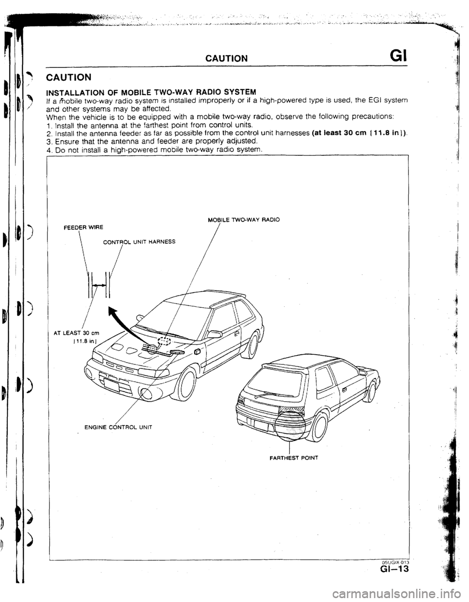
INSTALLATION OF MOBILE TWO-WAY RADIO SYSTEM
If a rkobile two-way radio system is installed improperly or if a high-powered type is used, the EGI system
and other systems may be affected.
When the vehicle is to be equipped with a mobile two-way radio, observe the following precautions:
1. Install the antenna at the farthest point from control units.
2. lnstatt the antenna feeder as far as possible from the control unit harnesses (at least 30 cm [ If .8 in 1).
3. Ensure that the antenna and feeder are properly adjusted.
4. Do not instali a high-powered mobile two-way radio svstem.
AT MOBlLE TWO-WAY RADIO
FARTHEST POINT
Page 17 of 279

..,. .
a
._
GI CAUTKN
PRECAUTIONS TO TAKE WHEN SERVICING AN ELECTRICAL SYSTEM l Note the following items when servicing the electrical system.
l Do not alter the wiring or electrical equipment in any way; this may damage the vehicle or cause a fire
from short-circuiting a circuit or overloading it.
l The negatrve (-) battery cable must be removed first and
rnstalled last. l Do not reptace with fuses exceedrng specified capacity
Cautron
l 8e sure that the ignitton and other switches are off
before disconnectrng or connecting the battery cables.
Failure to do so may damage the semrconductor
components. Caution l Repfacing a fuse with one of a larger capacrty than
desrgnated may damage components or cause a frre.
l Secure harnesses with provrded clamps to take up slack. l Tape areas of the harness
that may rub or bump l When mounting
components, be sure the
against sharp edges to
protect rt from damage. harness IS not caught or
damaged.
Caution
l Clamp all harnesses near vibratrng components (for
example, the engine) to remove slack and to prevent
contact resultrng from vibration. i Drsconnect heatsensitive l Make sure that the
parts (for example, relays
and ECU) when performing connectors are securely
connected when installed.
l Do not handle electrical components roughly or drop
them. maintenance (such as
weldrng) where
temperatures may exceed
80°C [176OFj.
-*
HI
Page 18 of 279

CAUTION GI
HANDLING CONNECTORS
Caution
*‘Be sure to grasp the connectors, not the wires, when disconnecting them.
1. Raise the rear
2. Lift the tab with a
thin piece of metal
and remove the
poor termrnat contact.
Lift the tab with a thin
When using a matching Make sure the termmals
male terminal, make are
not pushed out of
sure there
IS no
c Round connectors >
1. Raise the cover.
2. Lift the termrnal to
3. Make sure the
terminal is securely
mounted in the
Pull lightty on individual
wires to check that they
are secured rn the 1. Raise the cover.
2. Remove A.
3. Lift the tab with a
thin piece of metal
and remove the
Page 19 of 279

:
.
GI CAUTION
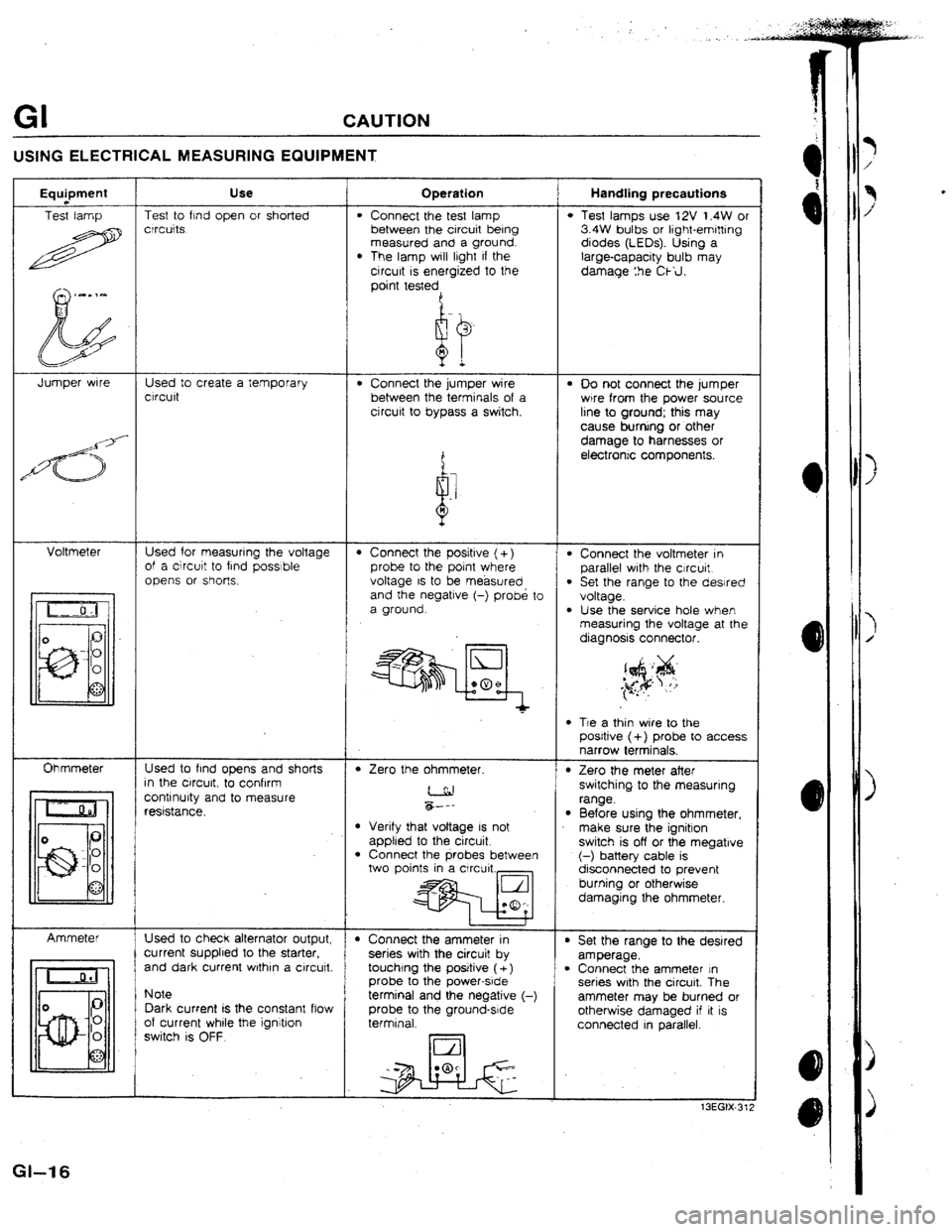
USING ELECTRICAL MEASURING EQUIPMENT
Use Handling precautions Operation Equpment
Test lamp Test to find open or shorted
crrcuits
l Connect the test lamp
between the circuit being
measured and a ground.
l The lamp will lrght if the
circurt is energized to the
point testedA
l Test lamps use 12V t.4W or
3.4W bulbs or light-emitting
diodes (LEOs). Using a
large-capacity bulb may
damage :he Ckil.
Jumper wrre Used to create a temporary
ctrcult . Connect the jumper wire
between the terminals of a
cjrcurt to bypass a switch. l 00 not connect the lumper
wrre from the power source
line to ground; this may
cause burning or other
damage to harnesses or
electrontc components.
Voltmeter Used for measuring the voltage
of a circutt to find possible
opens or shot-k.
l Connect the voltmeter in
parallel wrth the cjrcurt.
l Set the range to the dewed
voltage.
l Use the service hole when measuring the voltage at the
diagnosis connector.
l Connect the positive (+)
probe to the point where
voltage IS to be. measured
and the negatrve (-) probe to
a ground.
l Tie a thin wire to the
posrtive (+) probe to access
narrow terminals.
Ohmmeter Used to find opens and shorts
In the ctrcurt, to confrrm
contrnurty and to measure
reststance.
l Zero the ohmmeter. l Zero the meter after
switching to the measuring
range.
l Before using the ohmmeter,
make sure the ignitron
switch is off or the megatrve
(-) battery cable is
disconnected to prevent
burning or otherwise
damaging the ohmmeter. &--- l Verify that voltage IS not
applied to the circuit
l Connect the probes between
two points in a Circuit.,
t I t
+ Connect the ammeter in
series with the circuit by
touchtng the positive ( +)
probe to the power-srde
terminal and the negative (-
probe to the ground-srde
terminal. Ammeter
Used to check alternator output,
current supplied to the starter.
and dark current wrthrn a circutt. l Set the range to the desired
amperage.
l Connect the ammeter In
series with the circuit. The
ammeter may be burned or
otherwise damaged if it IS
connected in parallel. Note
Dark current IS the constant flow
of current whrle
the ignitron
switch is OFF.
13EGIX-31;
Gl-t 6
Page 20 of 279

c
PRE-DELIVERY INSPECTION
AND
SCHEDULED MAINTENANCE
SERVICES
ME-DELIVERY INSPECTION TABLE . . . . . . . . . . A- 2
SCHEDULED MAINTENANCE SERVICES . . . . . A- 3
MAINTENANCE TABLE ..*.*.............,....**a,. A- 3
REMARKS . ..*...*...............**~.*...*.....t...*... A- 3
13EOAX.301