MAZDA 323 1992 Suplement Owner's Guide
Manufacturer: MAZDA, Model Year: 1992, Model line: 323, Model: MAZDA 323 1992Pages: 279, PDF Size: 24.15 MB
Page 31 of 279

EXHAUST ViitVE
EXHAUST SIDE
VALVE GUIDE
METALLIC SODIUM
(ABOUT 30% VOLUME)
VALVE STEM
.‘.‘*
:::I
:::I
VALVE HEAD
CYttNDER HEAD
IDENTlFtCATION OF METALLIC SODIUM-FILLED EXHAUST VALVE
l Superior he& dissipating .metallic sodium-filled exhaust valves are adopted. During engine operation, the
metalic sodium inside the valve stem melts. As the valve moves up and down, the sodium splashes around
inside the valve and helps to absorb heat from the cylinder head and to transfer it back to the engine
coolant through the valve guide. In this way, the combustion chamber temperature is reduced, reducing
knocking and improving fuel efficeincy.
l Special handling of sodium filled valves is required for personal safety. (See next page.)
B2-7
Page 32 of 279
82 INSTRUCTlUN FOR HANDLING METALUC SODIUM-FltLED EXHAUST VALVE
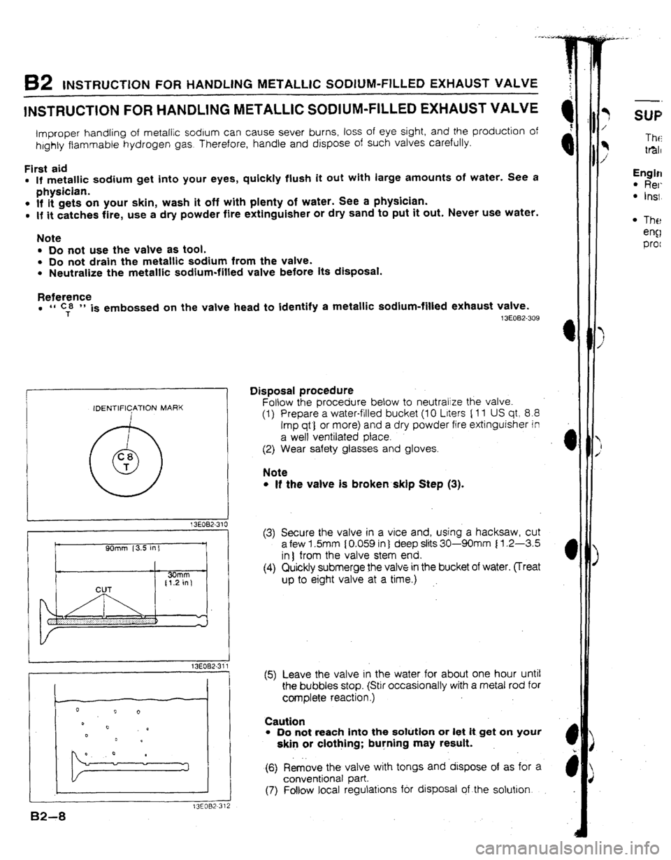
1NSTRUCTION FOR IiANDLlNG METALLIC SODIUM-FILLED EXHAUST VALVE
improper handling of metallic sodium can cause sever burns, loss of eye sight, and the production of
htghty ftammabie hydrogen gas. Therefore, handle and dispose of such valves carefully.
First aid
l If metallic sodium get into your eyes, quickly fiush it out with large amounts of water. See a
physician.
l If it gets on your skin, wash it off with plenty of water. See a physician.
l If it catches fire, use a dry powder fire extinguisher or dry sand to put it out. Never use water.
Note
l Do not use the valve as tool.
l Do not drain the metaltic sodium from the vatve.
l Neutralize the metallic sodium-filled valve before its disposal.
Re!e;,nEe
l
T is embossed on the valve head to identify a metallic sodium-filled exhaust valve. 13E082-309
IDENTIFICATION MARK
0 C8
T
9Omm 13.5 in] Disposal procedure
Follow the procedure below to neutralize the valve.
(1) Prepare a water-filled bucket (10 Liters [ 11 US qt? 8.8
Imp qtj or more> and a dry powder fire extinguisher in
a well ventilated place.
(2) Wear safety glasses and gloves.
Note
l If the valve is broken skip Step (3).
I
1 X002-31 1
, (3) Secure the valve in a vice and, using a hacksaw, cut
a few 1.5mm [ 0.059 in) deep slits 30-90mm 11.2-3.5
in) from the valve stem end.
(4) Quickly submerge the valve in the bucket of water. vreat
up to eight valve at a time.)
:
1
t3EOB2-312 (5) Leave the valve in the water for about one hour until
the bubbles stop. (Stir occasionally with a metat rod for
complete reaction.)
Caution
l Do not reach into the solution or let it get on your
skin or clothing; burning may result.
(6) Remove the valve with tongs and dtspose of as for a
conventional part.
(7) Follow local regulations fbr disposal of the solution. /
q Tht-i
i tmr
Engin
l Rer.
l Ins;
l The
eng
proc
Page 33 of 279
SUPPLEMENTAL SERVICE HWURMATION B2
SUPPLEMENTAL SERVICE 1NFORMATION
The following points in this section are changed in comparison with 323 Workshop Manual [Europe, AUS- tfilia (I 229-I O-89L)j.
Engine
l Removal
. Installation
I
m I
l The intercooler installation position is changed because the intercooler is enlarged. With this change, the
engine can be removed and ‘installed without removing the intercooler. The engine removal I installation
procedure is the same as of the previous BP-DOHC Turbo engine.
13E082-313
82-9
Page 34 of 279

F3
c
FUEL AND EMISSION
CONTROL
SYSTEMS
i
INDEX . . . . . . . . l ..,.... *..,. . . . . . . m...*.*...*..... F3- 2
UUTLtNE
...................................... F3- 4
OUTLINE OF CONSTRUCTION.. ....
F3- 4
SYSTEM DIAGRAM ...................... F3- 5
VACUUM HOSE ROUTING
DIAGRAM
................................. F3- 6
WIRING DIAGRAM.. .....................
F3- 7
ECU RELATIONSHIP DIAGRAM ...... F3- 8
SPECIFICATIONS.. ....................... F3- 9
TURBOCHARGER CONTROL .......... F3-IO
OUTLINE
.................................... F3-10
SYSTEM DIAGRAM ...................... F3-10
WASTEGATE CONTROL ............... F3-11
FUEL SYSTEM
.............................. F3-12
OUTLINE ....................................
F3-12
CONTROL SYSTEM .......................
F3-13
STRUCTURAL VIEW .....................
F3-13
PRESSURE REGULATOR
CONTROL SYSTEM ....................
F3-14 SUPPLEMENTAL SERVICE
tNFOF?MATtON
............................. F3-I 5
SELF-DtAGNOStS FUNCTtON.. ........
F3-16
OUTLINE ....................................
F3-16
SERVICE CODE NUMBERS..
......... F3-16
TROU8LESHOOTtNG GUtDE
........... F3-19
RELATIONSHtP
CHART.. F3-19 ..............
DIAGNOSTIC JNDEX
.................... F3-20
PRECAUTIONS
............................
F3-21
SYMPTOM TROUBLESHOOTING .... F3-22
TURBOCHARGERCONTROL
SYSTEM ......................................
F3-37
TURBOCHARGER F3-37 ........................
WASTEGATE SOLENOID VALVE.. .. F3-38
INTERCOOLER ............................
F3-39
FUELSYSTEM ..............................
F3-40
FUEL PUMP ................................
F3-40
FUEL PUMP RESISTOR/RELAY ......
F3-40
PRESSURE
REGULATOR .............. F3-41
INJECTOR ..................................
F3-42
INJECTOR RESISTOR
................... F3-42
PRESSUR REGULATOR CONTROL
SYSTEM ......................................
F3-43
SOLENOID VALVE (PRESSURE
REGULATOR CONTROL)
............. F3-43
CONTROL SYSTEM
....................... F3-44
PREPARATION ............................ F3-44
ENGINE CONTROL UNIT (ECU) ..... F3-45
7 3EOF3-301
Page 35 of 279
F3 INDEX
INDEX
I
J
D1AGNOSIS
CONNECTOR
SELF-DlAGNOSIS
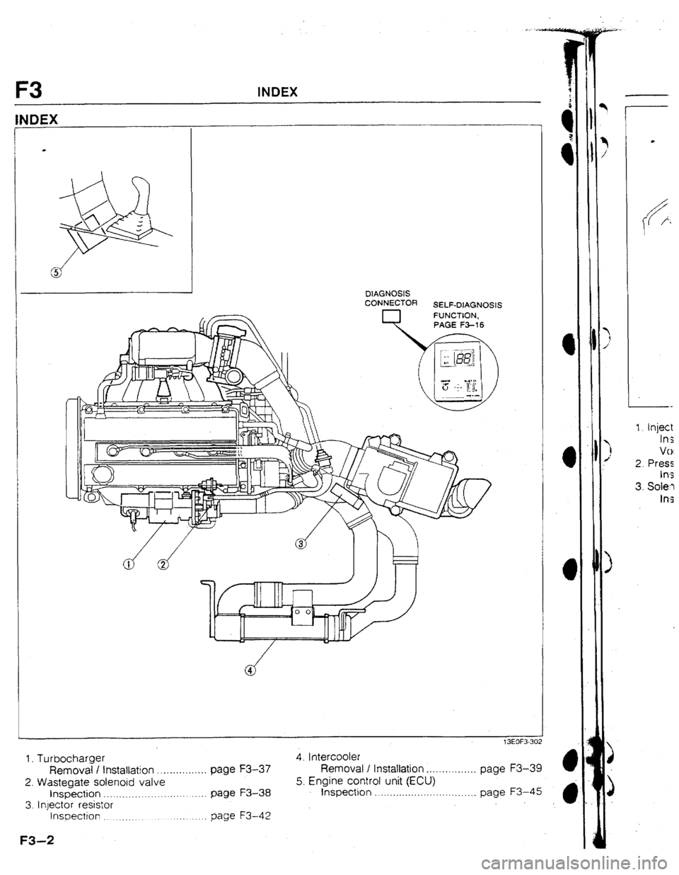
1. Turbocharger
Removal I installation . . . . . . . . . . . . . . . . page F3-37
2. Wastegate solenoid valve
inspection . .__._. ._. . . . . . . . . . page W-38
3. Injector resistor
Inspection __ __,., __ . page F3-42 4, I ntercooler
Removal / Installation . . . . . . . .._...... page F3-39
5. Engine control unit (ECU)
lnspect~on . . . . . .._........... . . . . . . . . . . . page F3-45
F3-2
--
I. Inject
IfI;
Vr,
2. Press
In3
3. Sole-l
Ins
Page 36 of 279
INDEX F3
t
3EOf3.303
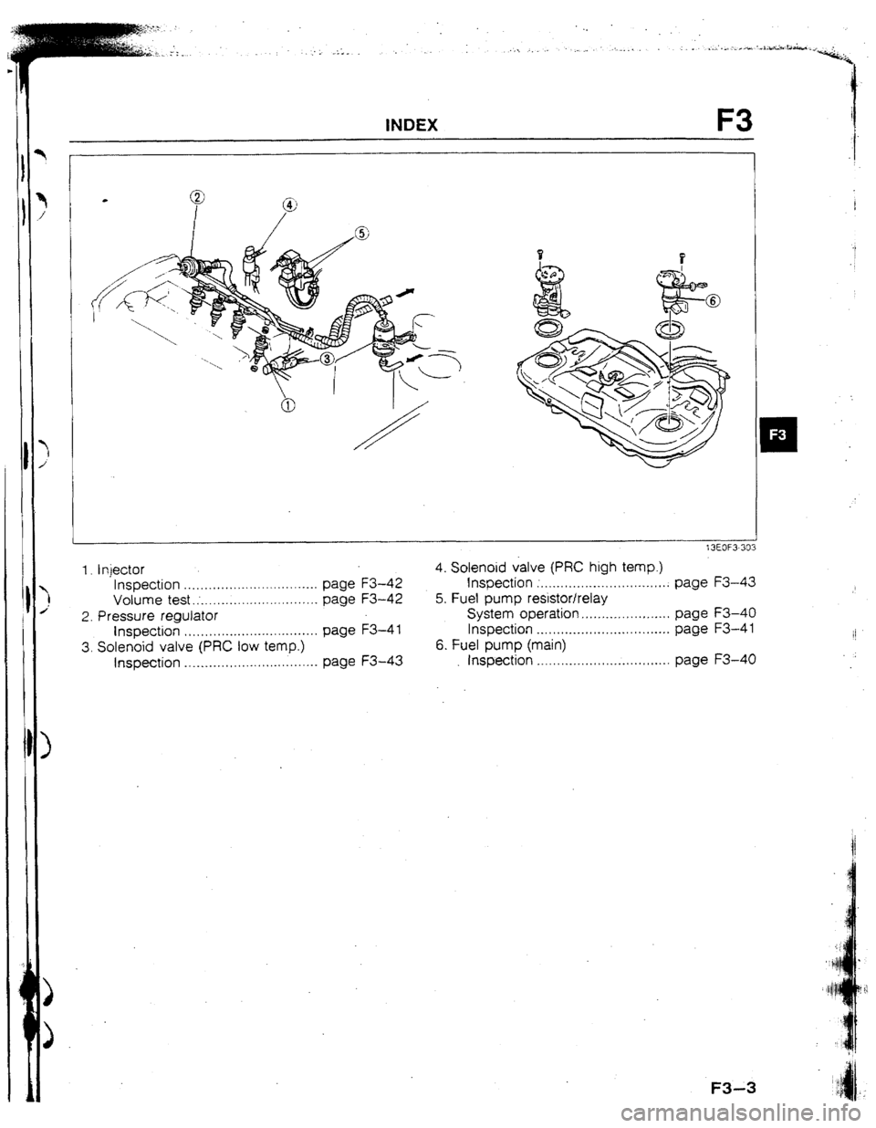
1. Injector 4. Solenoid valve (PRC high temp.)
Inspection ................................. page F3-42 Inspection ;. ............................... page F3-43
Volume test.; ............................. page F3-42 5. Fuel pump resistor/relay
2. Pressure regulator System operation ...................... page F3-40
Inspection ................................. page F3-4 1 Inspection ....... . .........................
page F3-4 1
II
3. Solenoid valve (PRC low temp.) 6. Fuel pump (main)
Inspection ................................. page F3-43 Inspection .......... . ...................... page F3-40
Page 37 of 279

F3 OUTLINE
OUTLINE
OUTLINE OF CONSTRUCTION
Theefuel and emission control system of the new 323 4WD model 1s basically the same as that of the prevr-
ous 323 4WD model; however some parts are changed. The changed parts and interchangable parts
are shown betow.
13EOF3-304
Changed parts
1 ~ components Contents and purpose Reference pagl
INTAKE AlR
SYSTEM Turbocharger
Intercooler
l Size Increased for greater boost pressure l Wastegate solenord valve IS lozated on Intake port of F3-10
turbocharger to make system more compact F3-37
Volume increased for Improved F3-10
t F3-39
Wastegate sojenold valve
l Wastegate solenoid valve changed to duty solenoid
type for Increased engine power and response
l Wastegate solenoid valve is located on Intake port of
turbocharger to make system more compact F3-1 f
F3-38
I r
Pressure regulator One-stage operattlon changed to two-stage operatron F3-14
to improve hot restarting f3-41
L
FUEL SYSTEM High-ohmic type change to low-ohmrc type with exter-
Fuel qector na solenoid reslstor for improved fuel supply during F3-12
high-speed driving F3-42
Fuel pump reslstor Resistance reduced for
surer fuel supply F3-40
CONTROL
SYSTEM Pressure
regulator control system
Atr flow meter Two-stage operatton used to Improve hot restarting
Measures larger amount of air flow Increased power
Resistance values changed F3-t4
F3-43
F3- 9
f3EOF3-305 lnterchangable parts
tntake air system
l
Air valve
l Air bypass valve
l Air cleaner
l Air cleaner element
Fuel system
l Fuel filter assembly
l Fuel pu.mp (transfer
l Fuel vapor valve Control system
. l Throttle sensor
l Water thermosensor
l Knock sensor and control unit
l Oxygen sensor
l Fuel pump control unit
l Main relay
l Circuit opening relay
l Check valve (two-way) .
Evaporative system
l Charcoal canister
l Check valve (two-way)
13EOF3-306
F3-4
Page 38 of 279

CHECK VALVE SOLENOID VALVE
(PURGE CONTROL)
llll
*
SOLENOID VALVE
(PRC LOW TEMP.)
3 ~NTERCOOLERII’ I ,‘/ I
II II
’ f frrmvmlHHt-----lHt I -1 II II
IIt - --M:l, i -KNmK~[I~ ,
’ ISC VALVE
VALVE WATER CHAkCOAL
CANISTOR
CHECK VALVE
I FUEL FUEL FILTER
PUMP
I FUEL FILTER
TRANSFER
PUMP
AIRkLOW METER
(WITH INTAKE AIR THERMOSENSOR)
DISTRIBUTOR
CATALYTIC CONVERTER
l TO ENGINE CONTROL UNIT
Page 39 of 279
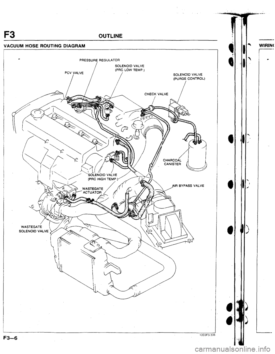
F3 OUTLINE
VACUUM HOSE ROUTING DIAGRAM
PRESSURE REGULATOR
IF1 BYPASS VALVE
Page 40 of 279
.
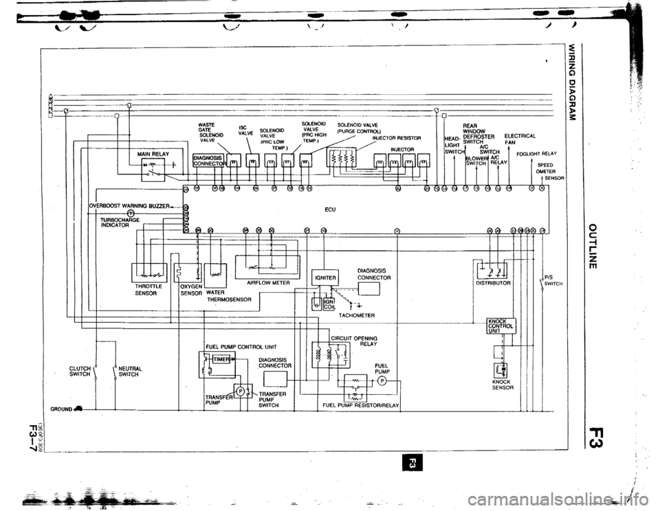
I I I I I tii I
ti I
I I
PIS
SWITCH
Q ‘.
;
E
p‘