air condition MAZDA 6 2002 Workshop Manual Suplement
[x] Cancel search | Manufacturer: MAZDA, Model Year: 2002, Model line: 6, Model: MAZDA 6 2002Pages: 909, PDF Size: 17.16 MB
Page 707 of 909

ON-BOARD DIAGNOSTIC
M–77
M
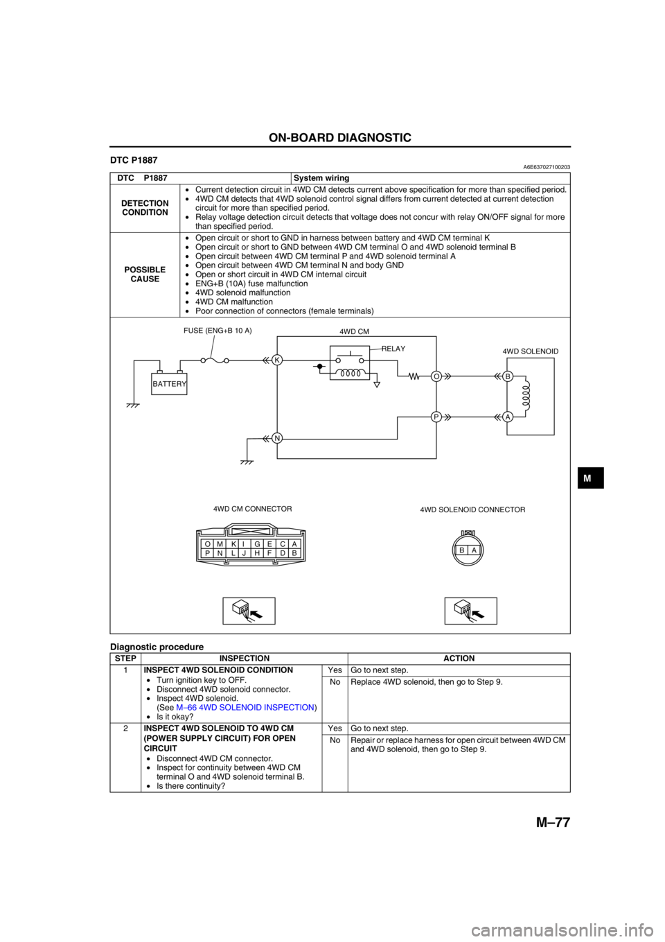
DTC P1887A6E637027100203
Diagnostic procedure
DTC P1887 System wiring
DETECTION
CONDITION•Current detection circuit in 4WD CM detects current above specification for more than specified period.
•4WD CM detects that 4WD solenoid control signal differs from current detected at current detection
circuit for more than specified period.
•Relay voltage detection circuit detects that voltage does not concur with relay ON/OFF signal for more
than specified period.
POSSIBLE
CAUSE•Open circuit or short to GND in harness between battery and 4WD CM terminal K
•Open circuit or short to GND between 4WD CM terminal O and 4WD solenoid terminal B
•Open circuit between 4WD CM terminal P and 4WD solenoid terminal A
•Open circuit between 4WD CM terminal N and body GND
•Open or short circuit in 4WD CM internal circuit
•ENG+B (10A) fuse malfunction
•4WD solenoid malfunction
•4WD CM malfunction
•Poor connection of connectors (female terminals)
STEP INSPECTION ACTION
1INSPECT 4WD SOLENOID CONDITION
•Turn ignition key to OFF.
•Disconnect 4WD solenoid connector.
•Inspect 4WD solenoid.
(See M–66 4WD SOLENOID INSPECTION)
•Is it okay?Yes Go to next step.
No Replace 4WD solenoid, then go to Step 9.
2INSPECT 4WD SOLENOID TO 4WD CM
(POWER SUPPLY CIRCUIT) FOR OPEN
CIRCUIT
•Disconnect 4WD CM connector.
•Inspect for continuity between 4WD CM
terminal O and 4WD solenoid terminal B.
•Is there continuity?Yes Go to next step.
No Repair or replace harness for open circuit between 4WD CM
and 4WD solenoid, then go to Step 9.
A A
B C
D E
F G
H I
J K
L M
N O
PB K
O B
A
N P BATTERYFUSE (ENG+B 10 A)
4WD CM
4WD CM CONNECTOR4WD SOLENOID
4WD SOLENOID CONNECTOR RELAY
Page 708 of 909

M–78
ON-BOARD DIAGNOSTIC
End Of Sie
3INSPECT 4WD SOLENOID TO 4WD CM
(POWER SUPPLY CIRCUIT) FOR SHORT TO
GROUND
•Inspect for continuity between 4WD CM
terminal O and ground.
•Is there continuity?Yes Repair or replace harness for short to ground between 4WD
CM and 4WD solenoid, then go to Step 9.
No Go to next step.
4INSPECT 4WD SOLENOID TO 4WD CM
(GROUND CIRCUIT) FOR OPEN CIRCUIT
•Inspect for continuity between 4WD CM
terminal P and 4WD solenoid terminal A.
•Is there continuity?Yes Replace 4WD CM, then go to next step.
No Repair or replace harness for open circuit between 4WD CM
and 4WD solenoid, then go to Step 9.
5INSPECT 4WD CM POWER SUPPLY CIRCUIT
FOR OPEN CIRCUIT
•Measure voltage between 4WD CM terminal
K and ground.
•Is voltage B+?Yes Replace 4WD CM, then go to Step 9.
No Go to next step.
6INSPECT 4WD CM TO BATTERY FOR OPEN
CIRCUIT
•Disconnect 4WD CM connector and battery
positive terminal.
•Inspect for continuity between 4WD CM
terminal K and battery positive terminal.
•Is there continuity?Yes Go to next step.
No Repair or replace harness for open circuit between 4WD CM
and battery positive terminal, then go to Step 9.
7INSPECT 4WD CM TO BATTERY FOR SHORT
TO GROUND
•Inspect for continuity between 4WD CM
terminal K and ground.
•Is there continuity?Yes Repair or replace harness for short to ground between 4WD
CM and battery positive terminal, then go to Step 9.
No Replace 4WD CM, then go to step 9.
8INSPECT FUSE CONDITION
•Turn ignition key to OFF.
•Is ENG+B fuse (10A) okay?Yes Go to next step.
No Replace fuse, then go to Step 9.
9VERIFY TROUBLESHOOTING COMPLETED
•Make sure to reconnect all disconnected
connectors.
•Clear DTC from memory.
(See M–76 Clearing DTCs Procedures)
•Drive vehicle.
•Is the same DTC present?Yes Replace 4WD CM, then go to next step.
No Go to next step.
10VERIFY AFTER REPAIR PROCEDURE
•Is there any other DTC present?Yes Go to applicable DTC inspection.
No Troubleshooting completed. STEP INSPECTION ACTION
Page 709 of 909

ON-BOARD DIAGNOSTIC
M–79
M
DTC P1888A6E637027100204
Diagnostic procedure
DTC P1888 Differential oil temperature sensor
DETECTION
CONDITION•Differential oil temperature sensor voltage monitor circuit detects abnormal input voltage.
POSSIBLE
CAUSE•Open circuit, or short to battery or GND between 4WD CM terminal A and differential oil temperature
sensor terminal A
•Open circuit or short to battery between 4WD CM terminal C and differential oil temperature sensor
terminal B
•Differential oil temperature sensor malfunction
•4WD CM malfunction
•Poor connection of connectors (female terminals)
STEP INSPECTION ACTION
1INSPECT DIFFERENTIAL OIL
TEMPERATURE SENSOR CONDITION
•Turn ignition key to OFF.
•Disconnect differential oil temperature
sensor connector.
•Is it okay?Yes Go to next step.
No Replace differential oil temperature sensor, then go to Step
7.
2INSPECT 4WD CM TO DIFFERENTIAL OIL
TEMPERATURE SENSOR FOR OPEN
CIRCUIT
•Disconnect 4WD CM connector.
•Inspect for continuity between 4WD CM
terminal A and differential oil temperature
sensor terminal A.
•Is there continuity?Yes Go to next step.
No Repair or replace harness for open circuit between 4WD CM
and differential oil temperature sensor, then go to Step 7.
3INSPECT 4WD CM TO DIFFERENTIAL OIL
TEMPERATURE SENSOR FOR SHORT TO
POWER
•Inspect voltage between 4WD CM terminal A
and ground.
•Is voltage B+?Yes Repair or replace harness for short to power between 4WD
CM and differential oil temperature sensor, then go to Step
7.
No Go to next step.
A B A
B C
D E
F G
H I
J K
L M
N O
PA
C A
B
4WD CM CONNECTOR4WD CM
DIFFERENTIAL OIL
TEMPERATURE SENSOR
DIFFERENTIAL OIL TEMPERATURE
SENSOR CONNECTOR
Page 710 of 909

M–80
ON-BOARD DIAGNOSTIC
End Of Sie
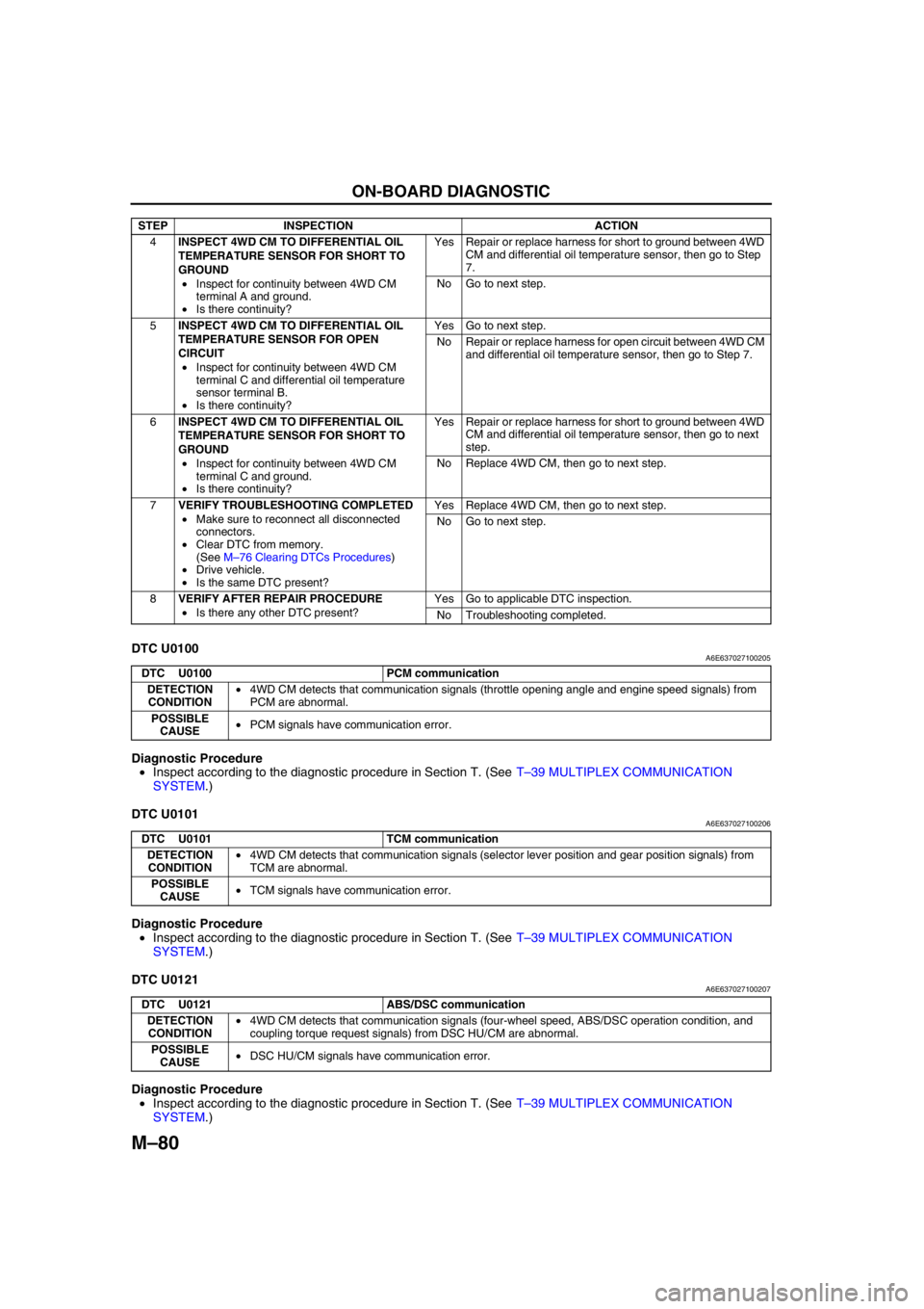
DTC U0100A6E637027100205
Diagnostic Procedure
•Inspect according to the diagnostic procedure in Section T. (See T–39 MULTIPLEX COMMUNICATION
SYSTEM.)
End Of Sie
DTC U0101A6E637027100206
Diagnostic Procedure
•Inspect according to the diagnostic procedure in Section T. (See T–39 MULTIPLEX COMMUNICATION
SYSTEM.)
End Of Sie
DTC U0121A6E637027100207
Diagnostic Procedure
•Inspect according to the diagnostic procedure in Section T. (See T–39 MULTIPLEX COMMUNICATION
SYSTEM.)
End Of Sie
4INSPECT 4WD CM TO DIFFERENTIAL OIL
TEMPERATURE SENSOR FOR SHORT TO
GROUND
•Inspect for continuity between 4WD CM
terminal A and ground.
•Is there continuity?Yes Repair or replace harness for short to ground between 4WD
CM and differential oil temperature sensor, then go to Step
7.
No Go to next step.
5INSPECT 4WD CM TO DIFFERENTIAL OIL
TEMPERATURE SENSOR FOR OPEN
CIRCUIT
•Inspect for continuity between 4WD CM
terminal C and differential oil temperature
sensor terminal B.
•Is there continuity?Yes Go to next step.
No Repair or replace harness for open circuit between 4WD CM
and differential oil temperature sensor, then go to Step 7.
6INSPECT 4WD CM TO DIFFERENTIAL OIL
TEMPERATURE SENSOR FOR SHORT TO
GROUND
•Inspect for continuity between 4WD CM
terminal C and ground.
•Is there continuity?Yes Repair or replace harness for short to ground between 4WD
CM and differential oil temperature sensor, then go to next
step.
No Replace 4WD CM, then go to next step.
7VERIFY TROUBLESHOOTING COMPLETED
•Make sure to reconnect all disconnected
connectors.
•Clear DTC from memory.
(See M–76 Clearing DTCs Procedures)
•Drive vehicle.
•Is the same DTC present?Yes Replace 4WD CM, then go to next step.
No Go to next step.
8VERIFY AFTER REPAIR PROCEDURE
•Is there any other DTC present?Yes Go to applicable DTC inspection.
No Troubleshooting completed. STEP INSPECTION ACTION
DTC U0100 PCM communication
DETECTION
CONDITION•4WD CM detects that communication signals (throttle opening angle and engine speed signals) from
PCM are abnormal.
POSSIBLE
CAUSE•PCM signals have communication error.
DTC U0101 TCM communication
DETECTION
CONDITION•4WD CM detects that communication signals (selector lever position and gear position signals) from
TCM are abnormal.
POSSIBLE
CAUSE•TCM signals have communication error.
DTC U0121 ABS/DSC communication
DETECTION
CONDITION•4WD CM detects that communication signals (four-wheel speed, ABS/DSC operation condition, and
coupling torque request signals) from DSC HU/CM are abnormal.
POSSIBLE
CAUSE•DSC HU/CM signals have communication error.
Page 712 of 909

M–82
TROUBLESHOOTING
FOREWORDA6E638027100202
End Of Sie
SYMPTOM TROUBLESHOOTINGA6E638027100203•Verify the symptoms, and perform troubleshooting according to the appropriate number.
End Of Sie
NO.1 FREQUENT FRONT WHEEL SLIPA6E638027100204
Warning
•During simulation driving, vehicle stability may decrease extremely and cause an accident. Be
sure to perform the simulation test driving in a safe area.
Malfunction vehicle delivered
Questionnaire
Verify malfunction symptoms
Symptom troubleshooting
Verify that malfunctions have been repaired
Troubleshooting completedConfirm all customer problems using a questionnaire.
Confirm malfunction on actual vehicle.
DTC inspection
Inspect for DTCs using WDS or equivalent.
Perform applicable troubleshooting inspection according to
diagnostic index.
A6E63802001
No. Symptom Description
1 Frequent front wheel slip Front wheels slip frequently during acceleration on low-friction road.
2
Tight corner braking effectBrakes seem to be applied during tight cornering while driving very
slowly on paved road.
3 Abnormal noise and/or vibration from
coupling unitThere is abnormal noise and/or vibration from coupling unit during
driving.
1 Frequent front wheel slip
[TROUBLESHOOTING HINTS]
•Tire traction performance is extremely poor for given road friction. (4WD system is normal.)
•Improper wheel alignment (4WD system is normal.)
•Rear differential oil temperature is extremely high (Fail-safe condition)
•Differential oil temperature sensor malfunction (Fail-safe condition)
•Compare slip frequency with another vehicle of the same model (under the same road conditions and tire traction
performance).
•Replace tires with others of the same model and perform test under the same road conditions to determine if the
malfunction was caused by tire traction performance.
•Coupling component malfunction
•4WD solenoid malfunction
Page 714 of 909

M–84
TROUBLESHOOTING
End Of Sie
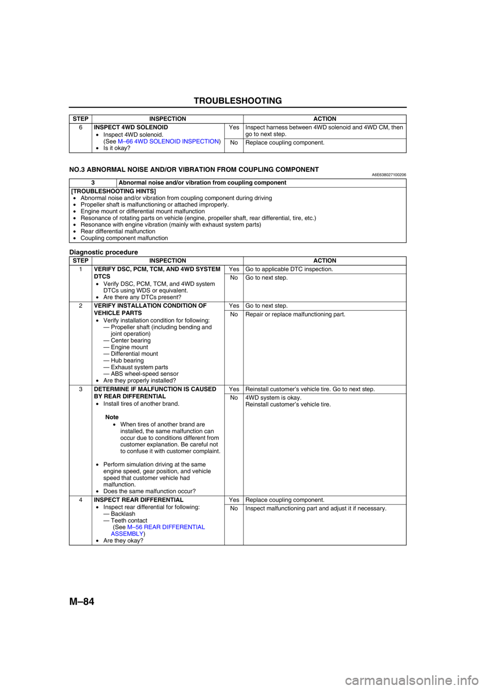
NO.3 ABNORMAL NOISE AND/OR VIBRATION FROM COUPLING COMPONENTA6E638027100206
Diagnostic procedure
End Of Sie
6INSPECT 4WD SOLENOID
•Inspect 4WD solenoid.
(See M–66 4WD SOLENOID INSPECTION)
•Is it okay?Yes Inspect harness between 4WD solenoid and 4WD CM, then
go to next step.
No Replace coupling component. STEP INSPECTION ACTION
3 Abnormal noise and/or vibration from coupling component
[TROUBLESHOOTING HINTS]
•Abnormal noise and/or vibration from coupling component during driving
•Propeller shaft is malfunctioning or attached improperly.
•Engine mount or differential mount malfunction
•Resonance of rotating parts on vehicle (engine, propeller shaft, rear differential, tire, etc.)
•Resonance with engine vibration (mainly with exhaust system parts)
•Rear differential malfunction
•Coupling component malfunction
STEP INSPECTION ACTION
1VERIFY DSC, PCM, TCM, AND 4WD SYSTEM
DTCS
•Verify DSC, PCM, TCM, and 4WD system
DTCs using WDS or equivalent.
•Are there any DTCs present?Yes Go to applicable DTC inspection.
No Go to next step.
2VERIFY INSTALLATION CONDITION OF
VEHICLE PARTS
•Verify installation condition for following:
—Propeller shaft (including bending and
joint operation)
—Center bearing
—Engine mount
—Differential mount
—Hub bearing
—Exhaust system parts
—ABS wheel-speed sensor
•Are they properly installed?Yes Go to next step.
No Repair or replace malfunctioning part.
3DETERMINE IF MALFUNCTION IS CAUSED
BY REAR DIFFERENTIAL
•Install tires of another brand.
Note
•When tires of another brand are
installed, the same malfunction can
occur due to conditions different from
customer explanation. Be careful not
to confuse it with customer complaint.
•Perform simulation driving at the same
engine speed, gear position, and vehicle
speed that customer vehicle had
malfunction.
•Does the same malfunction occur?Yes Reinstall customer’s vehicle tire. Go to next step.
No 4WD system is okay.
Reinstall customer’s vehicle tire.
4INSPECT REAR DIFFERENTIAL
•Inspect rear differential for following:
—Backlash
—Teeth contact
(See M–56 REAR DIFFERENTIAL
ASSEMBLY)
•Are they okay?Yes Replace coupling component.
No Inspect malfunctioning part and adjust it if necessary.
Page 762 of 909

ON-BOARD DIAGNOSTIC
P–29
PEnd Of Sie
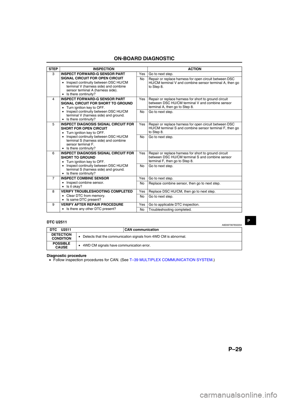
DTC U2511A6E697067650204
Diagnostic procedure
•Follow inspection procedures for CAN. (See T–39 MULTIPLEX COMMUNICATION SYSTEM.)
End Of Sie
3INSPECT FORWARD-G SENSOR PART
SIGNAL CIRCUIT FOR OPEN CIRCUIT
•Inspect continuity between DSC HU/CM
terminal V (harness side) and combine
sensor terminal A (harness side).
•Is there continuity?Yes Go to next step.
No Repair or replace harness for open circuit between DSC
HU/CM terminal V and combine sensor terminal A, then go
to Step 8.
4INSPECT FORWARD-G SENSOR PART
SIGNAL CIRCUIT FOR SHORT TO GROUND
•Turn ignition key to OFF.
•Inspect continuity between DSC HU/CM
terminal V (harness side) and ground.
•Is there continuity?Yes Repair or replace harness for short to ground circuit
between DSC HU/CM terminal V and combine sensor
terminal A, then go to Step 8.
No Go to next step.
5INSPECT DIAGNOSIS SIGNAL CIRCUIT FOR
SHORT FOR OPEN CIRCUIT
•Turn ignition key to OFF.
•Inspect continuity between DSC HU/CM
terminal S (harness side) and combine
sensor terminal F.
•Is there continuity?Yes Repair or replace harness for open circuit between DSC
HU/CM terminal S and combine sensor terminal F, then go
to Step 8.
No Go to next step.
6INSPECT DIAGNOSIS SIGNAL CIRCUIT FOR
SHORT TO GROUND
•Turn ignition key to OFF.
•Inspect continuity between DSC HU/CM
terminal S (harness side) and ground.
•Is there continuity?Yes Repair or replace harness for short to ground circuit
between DSC HU/CM terminal S and combine sensor
terminal F, then go to Step 8.
No Go to next step.
7INSPECT COMBINE SENSOR
•Inspect combine sensor.
•Is it okay?Yes Go to next step.
No Replace combine sensor, then go to next step.
8VERIFY TROUBLESHOOTING COMPLETED
•Clear DTC from memory.
•Is same DTC present?Yes Replace DSC HU/CM, then go to next step.
No Go to next step.
9VERIFY AFTER REPAIR PROCEDURE
•Is there any other DTC present?Yes Go to applicable DTC inspection.
No Troubleshooting completed. STEP INSPECTION ACTION
DTC U2511 CAN communication
DETECTION
CONDITION•Detects that the communication signals from 4WD CM is abnormal.
POSSIBLE
CAUSE•4WD CM signals have communication error.
Page 815 of 909

T–4
MULTIPLEX COMMUNICATION SYSTEM
SYSTEM WIRING DIAGRAMA6E811155430203
.
End Of SieCAN SIGNAL-CHARTA6E811155430204
OUT: Output (sends signal)
IN: Input (receives signal)
1
2
67
3
8
4
5
ROAF AG
HG
2M2J2W
2X
9
10
CAN_L
CAN_H
A6E81111102
1PCM
2 DSC HU/CM (with DSC)
3 ABS (ABS/TCS) HU/CM (with ABS (ABS/TCS))
4 Data link connector-2
5 Instrument cluster
6 TCM (JA5AX-EL)7 4WD control module (4WD)
8Twist pair
9 2R (except MZR-CD (RF Turbo))
39 (MZR-CD (RF Turbo))
10 2U (except MZR-CD (RF Turbo))
13 (MZR-CD (RF Turbo))
SignalMultiplex module
PCM TCMABS (ABS/TCS)
HU/CM or
DSC HU/CM4WD control
moduleInstrument
cluster
Accelerator pedal position
(MZR-CD (RF Turbo))OUT IN IN–IN
Air induction type OUT–IN––
ATF temperature IN OUT–––
AT warning light conditions
(JA5AX-EL)IN OUT––IN
Battery reconnection
(except MZR-CD (RF
Turbo))OUT IN–––
Brake system configuration
(EBD/ABS/TCS/DSC)IN–OUT–IN
Brake system
statusABS IN–OUT––
EBD/ABS/
TCS/DSC––OUT IN IN
Brake system warning light
conditions (brake fluid level
sensor)––IN–OUT
Country OUT–IN––
Coupling torque (with
DSC)––IN OUT–
Coupling torque request
(with DSC)––OUT IN–
Page 864 of 909

U–1
U
UHEATER AND AIR CONDITIONER SYSTEMS
OUTLINE................................................................ U-2
OUTLINE OF CONSTRUCTION.......................... U-2
FEATURES .......................................................... U-2
SPECIFICATIONS ............................................... U-2
CONTROL SYSTEM............................................... U-6
WATER HEATER SYSTEM................................. U-6
OUTLINE................................................................ U-7
SUPPLEMENTAL SERVICE INFORMATION .....U-7
LOCATION INDEX.................................................U-8
BASIC SYSTEM................................................... U-8
CONTROL SYSTEM ............................................ U-9
BASIC SYSTEM................................................... U-10
A/C UNIT REMOVAL/INSTALLATION...............U-10
A/C COMPRESSOR
REMOVAL/INSTALLATION ............................U-11
CONDENSER REMOVAL/INSTALLATION ....... U-12
REFRIGERANT LINES
REMOVAL/INSTALLATION ............................U-13
CONTROL SYSTEM............................................. U-15
WATER HEATER UNIT
REMOVAL/INSTALLATION ............................U-15
FUEL PUMP (WATER HEATER SYSTEM)
INSPECTION .................................................. U-16
CLIMATE CONTROL UNIT INSPECTION.........U-16
ON-BOARD DIAGNOSTIC...................................U-22
FOREWORD ......................................................U-22
DTC TABLE ................................................... U-22-2
PID/DATA MONITOR AND RECORD ........... U-22-2
DTC B1317 .................................................... U-22-3
DTC B1318 ........................................................ U-23
DTC B1342, B2463, B2537, B2538, B2547 ....... U-23
DTC B2449, B2450 ............................................ U-24
DTC B2451, B2452 ............................................ U-24
DTC B2453, B2454 ............................................ U-25
DTC B2548 ........................................................ U-25
TROUBLESHOOTING.......................................... U-26
FOREWORD ......................................................U-26
TROUBLESHOOTING INDEX ...........................U-26 FEATURES
SERVICE
Page 865 of 909

U–2
OUTLINE
OUTLINE OF CONSTRUCTIONA6E850201038201•The construction and operation of the air conditioner system is essentially carried over from that of the previous
Mazda6 (GG) model, except for the following features. (See Mazda6 Training Manual 3359-1*-02C.)
End Of Sie
FEATURESA6E850201038202Improved Comfort
•The water heater system has been adopted. (For MZR-CD (RF Turbo) European (L.H.D.) specs.)
End Of Sie
SPECIFICATIONSA6E850201038203Manual Air Conditioner
OUTLINE
ItemSpecification
L3, L8, LF MZR-CD (RF Turbo)
Heating capacity (kW {kcal/h}) 4.400 {3,784}4.400 {3,784} (L.H.D.)
5.120 {4,403} (R.H.D.)
Airflow volume
(during heater operation)Blower motor
(m
3/h)310 (L.H.D.)
300 (R.H.D.)
Electricity consumption
(during heater operation)Blower motor (W) 184
Cooling capacity (kW {kcal/h}) 4.200 {3,612}
Airflow volume (during air
conditioner operation)Blower motor
(m
3/h)460
Electricity consumption
(during air conditioner
operation)Blower motor (W) 225
Magnetic clutch (W) 46 45
Fan type Blower motor Sirocco fan
RefrigerantType R-134a
Regular amount
(approximate quantity)470 {16.6} (L.H.D.)
430 {15.2} (R.H.D.)
(g {oz})
A/C compressorType Vane-rotary
Discharge capacity
120 {120, 4.06}
(ml {cc, fl oz})
Max. allowable speed
6,400
(rpm)
Lube
oilType ATMOS GU10
Sealed volume
(approximate quantity)
120 {120, 4.06} 150 {150, 5.07}
(ml {cc, fl oz})
Magnetic clutch clearance
0.3—0.5 {0.012—0.019}
(mm {in})
CondenserType Multiflow (sub-cooling type)
Radiated heat (kW {kcal/h})4.69 {4,030}: European (L.H.D.) specs.
5.96 {5,130}: European (U.K.), GCC specs.
Receiver/drier
capacity(ml {cc, fl oz}) 190 {190, 6.42}
Desiccant Synthetic zeolite
Expansion valve Type Block type
Evaporator Type Double-tank drawn cup