light MAZDA 6 2002 Workshop Manual Suplement
[x] Cancel search | Manufacturer: MAZDA, Model Year: 2002, Model line: 6, Model: MAZDA 6 2002Pages: 909, PDF Size: 17.16 MB
Page 792 of 909

EXTERIOR ATTACHMENT
S–11
S
EXTRACTOR CHAMBER REMOVAL/INSTALLATIONA6E772851920201WGN
1. Remove the rear bumper.
2. Remove the left side trunk side trim.
3. Squeeze the clips with your fingers and remove
the extractor chamber from the vehicle side.
4. Install in the reverse order of removal.
End Of Sie
REAR SPOILER REMOVAL/INSTALLATIONA6E772851920202WGN
1. Disconnect the negative battery cable.
2. Remove the liftgate upper trim. (SeeS–23 LIFTGATE UPPER TRIM REMOVAL/INSTALLATION)
3. Remove the bolts and nuts.
4. Disconnect the high-mount brake light connector.
5. Disengage the pin A from the body, then remove
the rear spoiler.
6. Install in the reverse order of removal.
End Of Sie
ROOF RAIL REMOVAL/INSTALLATIONA6E7728517202011. Remove the headliner.
2. Remove the nuts.
3. Remove the roof rail.
4. Install in the reverse order of removal.
End Of Sie
EXTERIOR ATTACHMENT
EXTRACTOR
CHAMBER CLIP AA
A
A6E77281103
BOLT REAR SPOILER
HIGH-MOUNT BRAKE
LIGHT CONNECTOR
NUTPIN A
AA
N·m {kgf·cm, in·lbf} 7.8—9.8
{79—100, 68.8—86.7} 8.9—12.7 {90—130, 79—112}
A6A7728W104
ROOF RAIL
6.9—9.8 N·m
{70—100 kgf·cm,
60.8—86.7 in·lbf}NUT
A6A7728W105
Page 804 of 909

TRIM
S–23
S
TRUNK END TRIM REMOVAL/INSTALLATIONA6E774468890201WGN
1. Pull the trunk end trim upward, then disengage
clips A and pins B from the body.
2. Remove the trunk end trim.
3. Install in the reverse order of removal.
End Of Sie
LIFTGATE UPPER TRIM REMOVAL/INSTALLATIONA6E774468930201WGN
Without rear spoiler
Caution
•Removing the liftgate upper trim by pulling on the middle section of the trim could damage the
high-mount brake light. When removing the trim, be sure to pull on the side edges of the trim only.
1. Pull the liftgate upper trim on the side edges
towards you, then disengage pins A from the
body.
2. Pull the middle section of the trim towards you
and disengage clips B and pin C from the body.
3. Remove the liftgate upper trim.
4. Install in the reverse order of removal.
With rear spoiler
1. Pull the liftgate upper trim toward you, then
disengage the pin A, C and clip B from the body.
2. Remove the liftgate upper trim.
3. Install in the reverse order of removal.
End Of Sie
AB
A
A
B
A
A
A B
TRUNK END TRIM
PIN B
CLIP A
A6A7744W108
AC B
AB
CLIP B
PIN A LIFTGATE UPPER TRIM
PIN C
A6A7744W109
ABAB
C
CLIP BPIN C LIFTGATE UPPER TRIM
PIN A
A6A7744W110
Page 807 of 909

S–26
HEADLINER
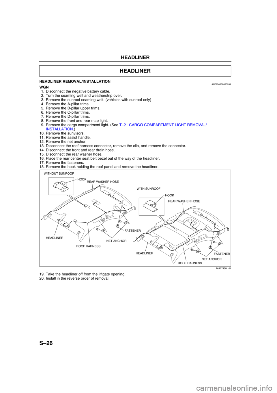
HEADLINER REMOVAL/INSTALLATIONA6E774668030201WGN
1. Disconnect the negative battery cable.
2. Turn the seaming welt and weatherstrip over.
3. Remove the sunroof seaming welt. (vehicles with sunroof only)
4. Remove the A-pillar trims.
5. Remove the B-pillar upper trims.
6. Remove the C-pillar trims.
7. Remove the D-pillar trims.
8. Remove the front and rear map light.
9. Remove the cargo compartment light. (See T–21 CARGO COMPARTMENT LIGHT REMOVAL/
INSTALLATION.)
10. Remove the sunvisors.
11. Remove the assist handle.
12. Remove the net anchor.
13. Disconnect the roof harness connector, remove the clip, and remove the connector.
14. Disconnect the front and rear drain hose.
15. Disconnect the rear washer hose.
16. Place the rear center seat belt bezel out of the way of the headliner.
17. Remove the fasteners.
18. Remove the hook holding the roof panel and remove the headliner.
19. Take the headliner off from the liftgate opening.
20. Install in the reverse order of removal.
End Of Sie
HEADLINER
HOOK
FASTENER
FASTENER ROOF HARNESS HEADLINERHOOK
ROOF HARNESS HEADLINER WITHOUT SUNROOF
WITH SUNROOF REAR WASHER HOSE
REAR WASHER HOSE
NET ANCHOR NET ANCHOR
A6A7746W101
Page 812 of 909

T–1
T
TBODY ELECTRICAL SYSTEM
OUTLINE................................................................ T-2
OUTLINE OF CONSTRUCTION ......................... T-2
FEATURES .......................................................... T-2
POWER SYSTEM................................................... T-2
STRUCTURAL VIEW........................................... T-2
MULTIPLEX COMMUNICATION SYSTEM............ T-3
OUTLINE ............................................................. T-3
STRUCTRURAL VIEW ........................................ T-3
SYSTEM WIRING DIAGRAM .............................. T-4
CAN SIGNAL-CHART.......................................... T-4
ON-BOARD DIAGNOSTIC FUNCTION............... T-6
EXTERIOR LIGHTING SYSTEM............................ T-8
OUTLINE ............................................................. T-8
STRUCTURAL VIEW........................................... T-8
INTERIOR LIGHTING SYSTEM............................. T-8
STRUCTURAL VIEW........................................... T-8
WIPER AND WASHER........................................... T-9
OUTLINE ............................................................. T-9
STRUCTURAL VIEW........................................... T-9
WARNING AND INDICATOR SYSTEM............... T-10
OUTLINE ........................................................... T-10
STRUCTURAL VIEW......................................... T-10
SYSTEM WIRING DIAGRAM ............................ T-11
THEFT-DETERRENT SYSTEM............................ T-11
OUTLINE ........................................................... T-11
INTRUDER SENSOR ........................................ T-11
AUDIO AND NAVIGATION SYSTEM.................. T-13
OUTLINE ........................................................... T-13
STRUCTURAL VIEW......................................... T-13
CRUISE CONTROL SYSTEM.............................. T-13
OUTLINE ........................................................... T-13
AIR BAG SYSTEM............................................... T-13
OUTLINE ........................................................... T-13
OUTLINE.............................................................. T-14
SUPPLEMENTAL SERVICE INFORMATION ... T-14
LOCATION INDEX............................................... T-15
POWER SYSTEM.............................................. T-15
EXTERIOR LIGHTING SYSTEM ....................... T-15
INTERIOR LIGHTING SYSTEM ........................ T-16
WIPER AND WASHER SYSTEM ...................... T-16
WARNING AND INDICATOR SYSTEM............. T-17
THEFT-DETERRENT SYSTEM ........................ T-17
AUDIO AND NAVIGATION SYSTEM ................ T-18
AIR BAG SYSTEM............................................. T-18
POWER SYSTEM................................................. T-19
RELAY LOCATION ............................................ T-19
RELAY INSPECTION ........................................ T-19
EXTERIOR LIGHTING SYSTEM.......................... T-20
REAR AUTO LEVELING SENSOR
REMOVAL/INSTALLATION ............................ T-20HIGH-MOUNT BRAKE LIGHT
REMOVAL/INSTALLATION ............................ T-20
INTERIOR LIGHTING SYSTEM........................... T-21
CARGO COMPARTMENT LIGHT
REMOVAL/INSTALLATION ............................ T-21
CARGO COMPARTMENT LIGHT
INSPECTION .................................................. T-22
WIPER AND WASHER......................................... T-22
REAR WIPER MOTOR
REMOVAL/INSTALLATION ............................ T-22
REAR WIPER MOTOR INSPECTION ............... T-22
REAR WIPER ARM AND BLADE
REMOVAL/INSTALLATION ............................ T-23
REAR WIPER ARM AND BLADE
ADJUSTMENT ................................................ T-24
REAR WASHER NOZZLE
REMOVAL/INSTALLATION ............................ T-24
REAR WASHER NOZZLE ADJUSTMENT ........ T-25
REAR WASHER HOSE
REMOVAL/INSTALLATION ............................ T-25
INTERMITTENT REAR WIPER RELAY
REMOVAL/INSTALLATION ............................ T-26
WARNING AND INDICATOR SYSTEM............... T-27
FUEL GAUGE SENDER UNIT
REMOVAL/INSTALLATION ............................ T-27
FUEL GAUGE SENDER UNIT INSPECTION.... T-28
THEFT-DETERRENT SYSTEM............................ T-29
INTRUDER SENSOR
REMOVAL/INSTALLATION ............................ T-29
AUDIO AND NAVIGATION SYSTEM.................. T-30
NOISE FILTER REMOVAL/INSTALLATION ..... T-30
CONDENSER REMOVAL/INSTALLATION ....... T-30
ANTENNA FEEDER LOCATION ....................... T-31
REAR ANTENNA FEEDER INSPECTION ........ T-31
AIR BAG SYSTEM............................................... T-32
SERVICE WARNINGS....................................... T-32
CURTAIN AIR BAG MODULE
REMOVAL/INSTALLATION ............................ T-35
AIR BAG MODULE AND PRE-TENSIONER
SEAT BELT DEPLOYMENT PROCEDURES. T-35
ON-BOARD DIAGNOSTIC
[MULTIPLEX COMMUNICATION SYSTEM].... T-39
MULTIPLEX COMMUNICATION SYSTEM ....... T-39
DTC TABLE ....................................................... T-41
PID/DATA MONITOR TABLE ............................ T-41
PROCEDURES FOR DETERMINING
THE LOCATION OF A MALFUNCTION ......... T-42
DTC U0073, U1900, U2516 ............................... T-45 FEATURES
SERVICE
Page 813 of 909

T–2
OUTLINE, POWER SYSTEM
OUTLINE OF CONSTRUCTIONA6E810201088201•The construction and operation of the body electrical system is essentially carried over from that of the current
Mazda6 (GG) model, except for the following features. (See Mazda6 Training Manual 3359-1*-02C)
End Of Sie
FEATURESA6E810201088202Improved Safety
•There are two types of high-mount brake lights. (WGN)
Improved Marketability
•A cargo compartment light has been adopted. (WGN)
•The installation positions of the rear wiper and washer components have been changed. (WGN)
•A fuel gauge sender sub-unit has been adopted. (4WD)
•A 4WD indicator light, glow indicator light and sedimentor warning light have been adopted.
•The installation positions of the condenser and the noise filter have been changed. (WGN)
•An antenna feeder has been adopted. (WGN)
•A rear auto leveling sensor especially for the 4WD has been adopted. (4WD)
Improved Security
•A rear intruder sensor has been adopted. (WGN)
End Of Sie
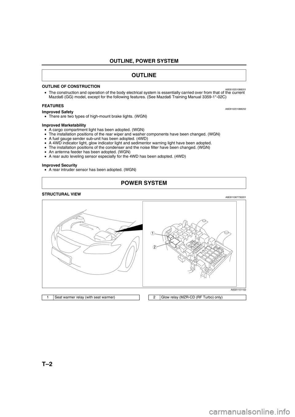
STRUCTURAL VIEWA6E811067730201
.
End Of Sie
OUTLINE
POWER SYSTEM
2
1
A6E81101102
1 Seat warmer relay (with seat warmer)2 Glow relay (MZR-CD (RF Turbo) only)
Page 815 of 909

T–4
MULTIPLEX COMMUNICATION SYSTEM
SYSTEM WIRING DIAGRAMA6E811155430203
.
End Of SieCAN SIGNAL-CHARTA6E811155430204
OUT: Output (sends signal)
IN: Input (receives signal)
1
2
67
3
8
4
5
ROAF AG
HG
2M2J2W
2X
9
10
CAN_L
CAN_H
A6E81111102
1PCM
2 DSC HU/CM (with DSC)
3 ABS (ABS/TCS) HU/CM (with ABS (ABS/TCS))
4 Data link connector-2
5 Instrument cluster
6 TCM (JA5AX-EL)7 4WD control module (4WD)
8Twist pair
9 2R (except MZR-CD (RF Turbo))
39 (MZR-CD (RF Turbo))
10 2U (except MZR-CD (RF Turbo))
13 (MZR-CD (RF Turbo))
SignalMultiplex module
PCM TCMABS (ABS/TCS)
HU/CM or
DSC HU/CM4WD control
moduleInstrument
cluster
Accelerator pedal position
(MZR-CD (RF Turbo))OUT IN IN–IN
Air induction type OUT–IN––
ATF temperature IN OUT–––
AT warning light conditions
(JA5AX-EL)IN OUT––IN
Battery reconnection
(except MZR-CD (RF
Turbo))OUT IN–––
Brake system configuration
(EBD/ABS/TCS/DSC)IN–OUT–IN
Brake system
statusABS IN–OUT––
EBD/ABS/
TCS/DSC––OUT IN IN
Brake system warning light
conditions (brake fluid level
sensor)––IN–OUT
Country OUT–IN––
Coupling torque (with
DSC)––IN OUT–
Coupling torque request
(with DSC)––OUT IN–
Page 816 of 909

MULTIPLEX COMMUNICATION SYSTEM
T–5
T
End Of Sie
Cruise main indicator light
conditions (MZR-CD (RF
Turbo))OUT–––IN
Cruise set indicator light
conditions (MZR-CD (RF
Turbo))OUT–––IN
Desired gear/
selector lever
positionFN4A-EL OUT–IN–IN
JA5AX-EL IN OUT IN IN IN
ECT OUT IN–IN
Engine control condition OUT–IN––
Engine displacement OUT–IN––
Engine loss torque (except
MZR-CD (RF Turbo))OUT IN–––
Engine speed OUT IN IN IN IN
Engine torque (except
MZR-CD (RF Turbo))OUT IN–––
Fuel injection information OUT–IN––
Fuel type and delivery OUT–IN––
Gear position IN OUT IN IN IN
Generator warning light
conditions (except MZR-
CD (RF Turbo))OUT–––IN
Glow indicator light
condition (MZR-CD (RF
Turbo))OUT–––IN
HOLD indicator light
conditions (FN4A-EL)OUT–––IN
Idle speed up request IN OUT–––
MIL condition (except
MZR-CD (RF Turbo))OUT–––IN
MIL indicate request IN OUT–––
Number of cylinders OUT–IN––
Racing select
determinationIN OUT–––
TCC condition IN OUT–––
Tire circumference (front/
rear)OUT–IN––
Torque reduction inhibit OUT IN IN––
TP OUTINININ–
Transmission/axle type OUT–IN––
Travelled distanceIN–OUT––
IN OUT––IN
OUT–––IN
Torque
reduction
requestJA5AX-EL IN OUT–––
except
JA5AX-ELIN–OUT––
Turbine speed IN OUT–––
Upper torque limit IN OUT–––
Vehicle speedOUT–––IN
IN OUT–––
Wheel speed (front left/
front right/rear left/rear
right)IN IN OUT IN–
OUT–––IN
4WD system operating
condition (warning light
information)–––OUT IN SignalMultiplex module
PCM TCMABS (ABS/TCS)
HU/CM or
DSC HU/CM4WD control
moduleInstrument
cluster
Page 817 of 909

T–6
MULTIPLEX COMMUNICATION SYSTEM
ON-BOARD DIAGNOSTIC FUNCTIONA6E811155430205Outline
•The on-board diagnostic function is incorporated into the PCM, TCM, ABS (ABS/TCS) HU/CM (with ABS (ABS/
TCS)), DSC HU/CM (with DSC), 4WD control module, and instrument cluster. This function can narrow down
CAN system malfunction locations.
•Due to the adoption of the TCM and the 4WD CM, some DTCs and PID/data monitor items have been added.
Other functions are the same as those of the current Mazda6 (GG) model.
Block Diagram
.
Fail-Safe Function
•When the failure detection function detemines that there is a malfunction, the fail-safe function illuminates a
warning light to advise the driver of the malfunction.
1
3
24
5
6
A6E81111103
1PCM
2 TCM (JA5AX-EL)
3 ABS (ABS/TCS) HU/CM or DSC HU/CM4 4WD control module (4WD)
5 Instrument cluster
6Twist pair
Module Fail-safe function
PCM•MIL illuminated
TCM•AT warning light illuminated
•ABS (ABS/TCS) HU/CM (with ABS (ABS/TCS))
•DSC HU/CM (with DSC)•ABS (ABS/TCS) suspended (with ABS (ABS/TCS))
•DSC suspended (with DSC)
•ABS warning light illuminated
•DSC/TCS indicator light illuminated
•DSC OFF light illuminated
•TCS OFF light illuminated
4WD control module•4WD indicator light illuminated
Instrument cluster•Speedometer, tachometer, water temperature gauge: 0 displayed
Page 819 of 909

T–8
EXTERIOR LIGHTING SYSTEM, INTERIOR LIGHTING SYSTEM
OUTLINEA6E811201052201•In-vehicle-type high-mount brake light and rear spoiler type high-mount brake light have been adopted. (WGN)
End Of Sie
STRUCTURAL VIEWA6E811201052202
.
End Of Sie
STRUCTURAL VIEWA6E811401052201
.
End Of Sie
EXTERIOR LIGHTING SYSTEM
2
1
A6E8112T101
1 High-mount brake light (in-vehicle-type)2 High-mount brake light (rear spoiler type)
INTERIOR LIGHTING SYSTEM
FRONT
1
A6E81141001
1 Cargo compartment light
Page 821 of 909

T–10
WARNING AND INDICATOR SYSTEM
OUTLINEA6E811801069201•In accordance with the 4WD setting, the following indicator light has been added:
—4WD indicator light
•In accordance with the MZR-CD (RF Turbo) setting, the following indicator lights have been added:
—Glow indicator light
—Sedimentor warning light
•A fuel gauge sender sub-unit has been adopted. (4WD)
End Of Sie
STRUCTURAL VIEWA6E811801069202
.
End Of Sie
WARNING AND INDICATOR SYSTEM
3
2
1
4
5
4WD
A6E81181101
1 Sedimentor warning light
2 4WD indicator light
3 Glow indicator light4 Fuel gauge sender unit
5 Fuel gauge sender sub-unit