light MAZDA 6 2002 Workshop Manual Suplement
[x] Cancel search | Manufacturer: MAZDA, Model Year: 2002, Model line: 6, Model: MAZDA 6 2002Pages: 909, PDF Size: 17.16 MB
Page 645 of 909

ELECTRONIC 4WD CONTROL SYSTEM
M–15
M
Operation
Normal control
•When starting off or accelerating during straight-ahead driving, torque transmitted to the rear wheels is
optimally controlled to ensure sufficient acceleration performance. Due to this, standing-start and acceleration
performance is improved.
•Also, in order to improve fuel economy when driving at a stable, consistent speed, torque transmitted to the
rear wheels is damped, and rear-wheel drive is controlled to maintain it close to that of the front wheels.
Tight cornering control
•When the 4WD CM determines, based on the four-wheel speed signal, that the vehicle is in tight cornering, it
reduces the torque transmitted to the rear wheels to avoid tight corner braking characteristics.
Integrated DSC control
•If a signal from the DSC HU/CM input to the 4WD CM indicates that ABS control is activated, the module
controls the torque transmitted to the rear wheels to prevent undue influence on ABS control.
•Also, when a coupling torque request signal is received from the DSC HU/CM, the module controls the torque
transmitted to the rear wheels to match the amount of requested torque.
Other control
•In case the rear differential oil temperature exceeds the specified amount, or when there is an unusually large
variation in the rotation speed of the front and rear wheels (ex. when trying to get unstuck), control is
temporarily suspended in order to protect the 4WD system. When this occurs the 4WD warning light flashes to
indicate the situation to the driver.
End Of Sie
CONTROLLER AREA NETWORK (CAN)A6E632227100207Outline
•The 4WD CM transmits/receives information using the CAN system. See Section T for detailed information
regarding the CAN system.
Operation
Transmitted information
•Coupling torque
•4WD system operating condition (warning light information)
Received information
•Four-wheel speed
•Throttle opening angle
•Engine speed
•ABS/DSC operating condition
•Gear position
•Selector lever position
•Coupling torque request
End Of Sie
Page 646 of 909
M–16
ELECTRONIC 4WD CONTROL SYSTEM
ON-BOARD DIAGNOSTICA6E632227100208Outline
•The on-board diagnostic function allows for detecting malfunctions in the input/output signals when the ignition
key is at the ON position.
•The DLC-2, which combines the failure detection and detection maintenance connectors, has been adopted to
improve serviceability. By connecting a WDS or equivalent to the DLC-2, malfunction diagnosis can be carried
out.
•Using a WDS or equivalent DTCs can be retrieved or erased, depending on the screen display, thus improving
serviceability.
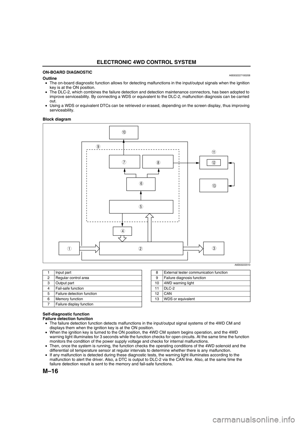
Block diagram
.
Self-diagnostic function
Failure detection function
•The failure detection function detects malfunctions in the input/output signal systems of the 4WD CM and
displays them when the ignition key is at the ON position.
•When the ignition key is turned to the ON position, the 4WD CM system begins operation, and the 4WD
warning light illuminates for 3 seconds while the function checks for open circuits. At the same time the function
monitors the condition of the power supply voltage and checks for internal malfunctions.
•Then, once the system is running, the function checks the operating conditions of the 4WD solenoid and the
differential oil temperature sensor at regular intervals to determine whether there is any malfunction.
•If any malfunction is detected during these diagnostic tests, the warning light illuminates according to the
malfunction to alert the driver. Also, a DTC is output to DLC-2 via the CAN line. Also, at the same time the
failure detection result is sent to the memory and fail-safe functions.
9
87
5
4
3
10
13
11
12
6
12
A6E63222010
1 Input part
2 Regular control area
3 Output part
4 Fail-safe function
5 Failure detection function
6 Memory function
7 Failure display function8 External tester communication function
9 Failure diagnosis function
10 4WD warning light
11 DLC-2
12 CAN
13 WDS or equivalent
Page 647 of 909

ELECTRONIC 4WD CONTROL SYSTEM
M–17
M
Memory function
•This function stores DTCs for malfunctions of the input/output signal systems as determined by the failure
detection function. Once a DTC is stored, it is not cleared even if the input/output signal system malfunction
returns to normal when the ignition key is turned to the LOCK position (engine OFF).
•Since DTCs are stored in the non-volatile memory inside the 4WD CM, they are not cleared even if the battery
is disconnected. Therefore, it is necessary to clear the memory when maintenance has been completed. For
clearing DTCs, refer to the procedures in the Workshop Manual.
•When inspecting DTCs using a WDS or equivalent, only one memory stored DTC at a time can be displayed.
Therefore, when multiple DTCs have been stored, it is necessary to inspect for DTCs again after repairing and
clearing the present DTC to ensure that there are no more DTCs present in the memory.
Fail-safe function
•When the failure detection function determines that there is a malfunction, the 4WD warning light illuminates to
alert the driver. At this time, the fail-safe function suspends control or takes other measures to ensure that
driving stability is not lost.
X:Available
*1: Does not illuminate when only the coupling torque request signal from the DSC HU/CM cannot be received.*2: Only integrated DSC control is prohibited when only the coupling torque request signal from the DSC HU/CM
cannot be received.
External tester communication function
•This function allows for the storing and clearing of DTCs due to a communication link between the 4WD CM
and an external tester.
End Of Sie
DTC Malfunction location4WD warning
lightconditionDTC stored in
memoryControl condition
P1887 System wiring Illuminated X Stop
P1888 Differential oil temperature sensor Illuminated X Stop
U0100 PCM communication system Illuminated X Stop
U0101 TCM communication system Illuminated X Stop
U0121 DSC communication system
Illuminated
*1X
Stop*2
Page 652 of 909
M–22
REAR AXLE
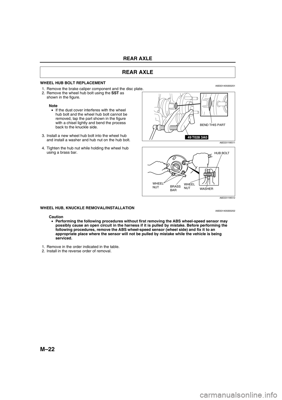
WHEEL HUB BOLT REPLACEMENTA6E6314050002011. Remove the brake caliper component and the disc plate.
2. Remove the wheel hub bolt using the SST as
shown in the figure.
Note
•If the dust cover interferes with the wheel
hub bolt and the wheel hub bolt cannot be
removed, tap the part shown in the figure
with a chisel lightly and bend the process
back to the knuckle side.
3. Install a new wheel hub bolt into the wheel hub
and install a washer and hub nut on the hub bolt.
4. Tighten the hub nut while holding the wheel hub
using a brass bar.
End Of Sie
WHEEL HUB, KNUCKLE REMOVAL/INSTALLATIONA6E631405000202
Caution
•Performing the following procedures without first removing the ABS wheel-speed sensor may
possibly cause an open circuit in the harness if it is pulled by mistake. Before performing the
following procedures, remove the ABS wheel-speed sensor (wheel side) and fix it to an
appropriate place where the sensor will not be pulled by mistake while the vehicle is being
serviced.
1. Remove in the order indicated in the table.
2. Install in the reverse order of removal.
REAR AXLE
49 T028 3A0
BEND THIS PART
A6E0311W011
HUB BOLT
WHEEL
NUT WHEEL
NUT
WASHER
BRASS
BAR
A6E0311W012
Page 684 of 909
M–54
REAR DIFFERENTIAL
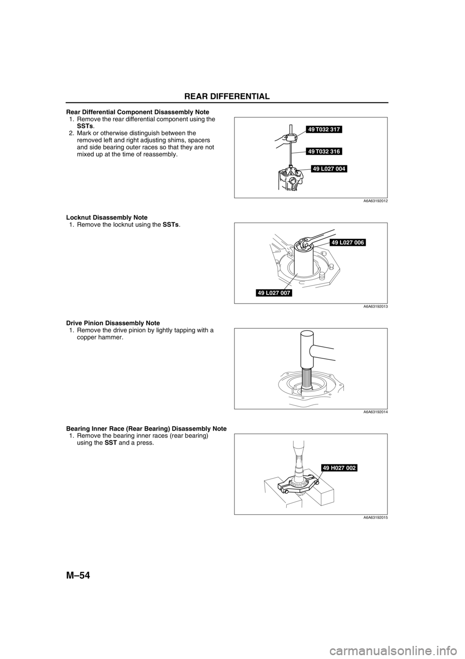
Rear Differential Component Disassembly Note
1. Remove the rear differential component using the
SSTs.
2. Mark or otherwise distinguish between the
removed left and right adjusting shims, spacers
and side bearing outer races so that they are not
mixed up at the time of reassembly.
Locknut Disassembly Note
1. Remove the locknut using the SSTs.
Drive Pinion Disassembly Note
1. Remove the drive pinion by lightly tapping with a
copper hammer.
Bearing Inner Race (Rear Bearing) Disassembly Note
1. Remove the bearing inner races (rear bearing)
using the SST and a press.
49 T032 317
49 T032 316
49 L027 004
A6A63192012
49 L027 006
49 L027 007
A6A63192013
A6A63192014
49 H027 002
A6A63192015
Page 685 of 909
REAR DIFFERENTIAL
M–55
M
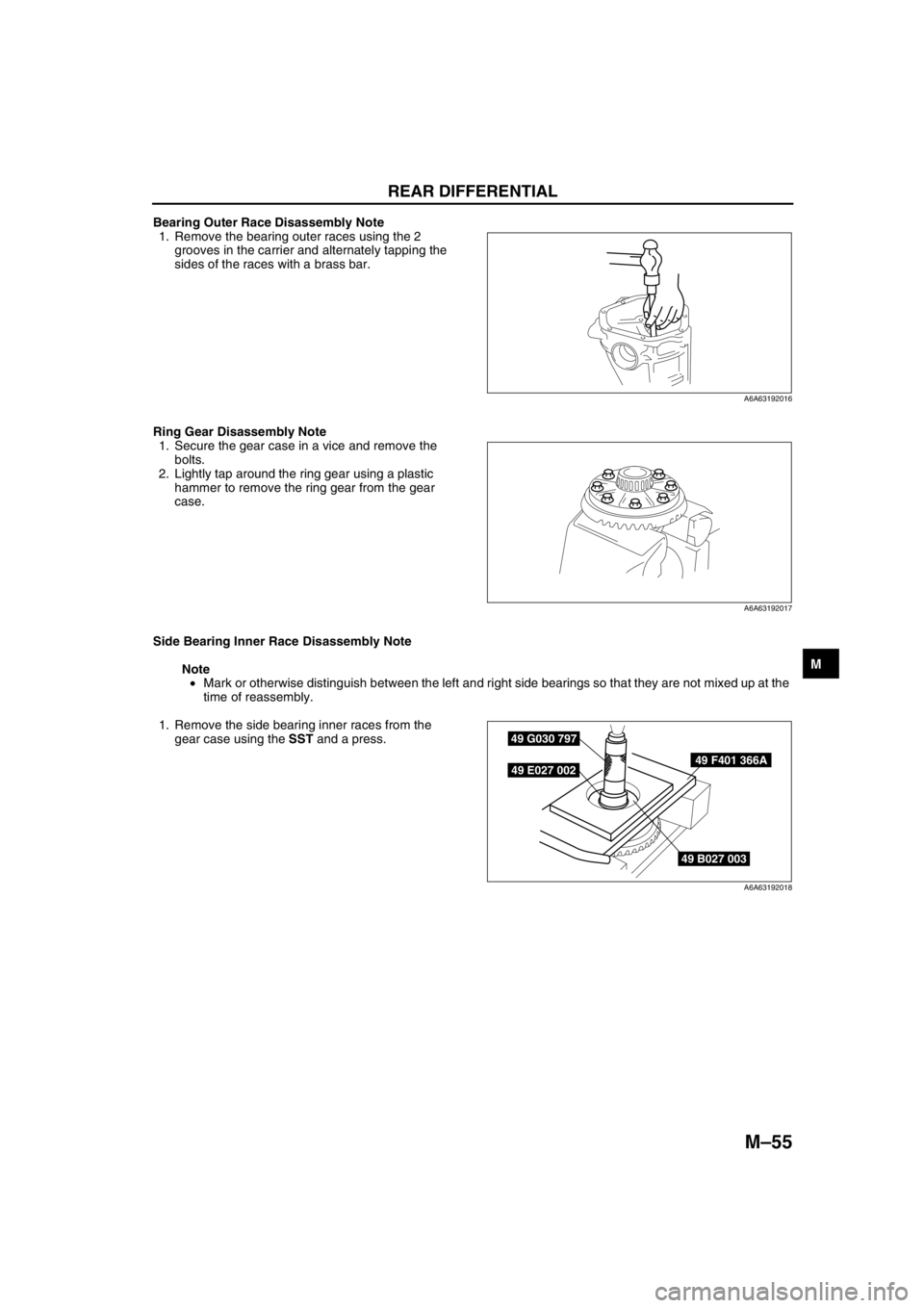
Bearing Outer Race Disassembly Note
1. Remove the bearing outer races using the 2
grooves in the carrier and alternately tapping the
sides of the races with a brass bar.
Ring Gear Disassembly Note
1. Secure the gear case in a vice and remove the
bolts.
2. Lightly tap around the ring gear using a plastic
hammer to remove the ring gear from the gear
case.
Side Bearing Inner Race Disassembly Note
Note
•Mark or otherwise distinguish between the left and right side bearings so that they are not mixed up at the
time of reassembly.
1. Remove the side bearing inner races from the
gear case using the SST and a press.
End Of Sie
A6A63192016
A6A63192017
49 B027 003
49 F401 366A
49 G030 797
49 E027 002
A6A63192018
Page 713 of 909

TROUBLESHOOTING
M–83
M
Diagnostic procedure
End Of Sie
NO.2 TIGHT CORNER BRAKINGA6E638027100205
Diagnostic procedure
STEP INSPECTION ACTION
1VERIFY DSC, PCM, TCM, AND 4WD SYSTEM
DTCs
•Verify DSC, PCM, TCM, and 4WD system
DTCs using WDS or equivalent.
•Are there any DTCs present?Yes Go to applicable DTC inspection.
No Go to next step.
2VERIFY TIRE AIR PRESSURE
•Inspect tire air pressure.
•Is it within specification?Yes Go to next step.
No Adjust tire air pressure, then go to next step.
3COMPARE WITH SAME MODEL TIRES
•Install tires of the same model.
•Perform simulation driving.
•Does malfunction recur?Yes Go to next step.
No 4WD system is okay.
4COMPARE WITH SAME MODEL VEHICLE
•Install tires of malfunctioning vehicle to
another same model vehicle.
•Perform simulation driving.
•Does malfunction recur?Yes 4WD system is okay.
No Go to next step.
5INSPECT 4WD SOLENOID
•Inspect 4WD solenoid.
(See M–66 4WD SOLENOID INSPECTION)
•Is coupling component solenoid okay?Yes Inspect harness between 4WD solenoid and 4WD CM, then
go to next step.
No Replace coupling component.
6INSPECT WHEEL ALIGNMENT
•Inspect wheel alignment.
•Is it okay?Yes Replace coupling component.
No Inspect wheel alignment, and adjust it if necessary.
2 Tight corner braking
[TROUBLESHOOTING HINTS]
•Because the coupling component locks up easily (similar to direct 4WD), rotational difference between the front
and rear wheels cannot be absorbed and brake-like phenomenon occurs.
•Due to the coupling component construction, slight tight corner braking effect occurs during tight cornering on a
paved road. (4WD system is okay. Compare with another same model vehicle to determine malfunction.)
•Coupling component malfunction
•4WD solenoid malfunction
STEP INSPECTION ACTION
1VERIFY DSC, PCM, TCM, AND 4WD SYSTEM
DTCS
•Verify DSC, PCM, TCM, and 4WD system
DTCs using WDS or equivalent.
•Are there any DTCs present?Yes Go to applicable DTC inspection.
No Go to next step.
2VERIFY TIRE AIR PRESSURE
•Inspect tire air pressure.
•Is it within specification?Yes Go to next step.
No Adjust tire air pressure, then go to next step.
3INSPECT ABS WHEEL-SPEED SENSOR
•Inspect ABS wheel-speed sensor.
•Is it okay?Yes Go to next step.
No Repair or replace malfunctioning part.
4COMPARE WITH SAME MODEL VEHICLE
•Perform simulation driving with another
same model vehicle.
•Does malfunction recur on the same model
vehicle?Yes 4WD system is okay.
No Go to next step.
5PERFORM SIMULATION DRIVING WITH 4WD
SOLENOID CONNECTOR DISCONNECTED
•Turn ignition key OFF.
•Disconnect 4WD solenoid connector.
•Perform simulation driving. (Clear DTC after
simulation driving.)
•Does malfunction recur?Yes Replace coupling component.
No Go to next step.
Page 722 of 909
N–8
ENGINE SPEED SENSING POWER STEERING
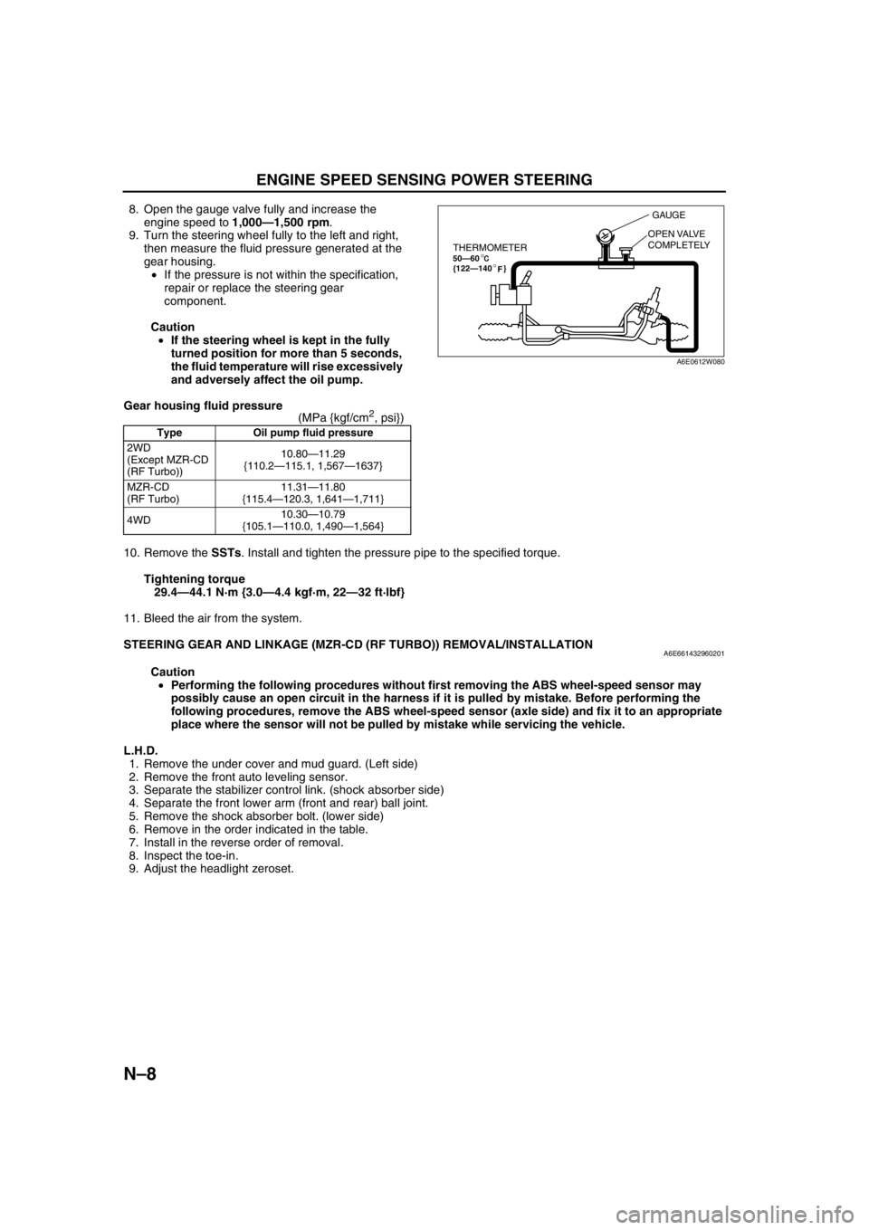
8. Open the gauge valve fully and increase the
engine speed to 1,000—1,500 rpm.
9. Turn the steering wheel fully to the left and right,
then measure the fluid pressure generated at the
gear housing.
•If the pressure is not within the specification,
repair or replace the steering gear
component.
Caution
•If the steering wheel is kept in the fully
turned position for more than 5 seconds,
the fluid temperature will rise excessively
and adversely affect the oil pump.
Gear housing fluid pressure
(MPa {kgf/cm
2, psi})
10. Remove the SSTs. Install and tighten the pressure pipe to the specified torque.
Tightening torque
29.4—44.1 N·m {3.0—4.4 kgf·m, 22—32 ft·lbf}
11. Bleed the air from the system.
End Of Sie
STEERING GEAR AND LINKAGE (MZR-CD (RF TURBO)) REMOVAL/INSTALLATIONA6E661432960201
Caution
•Performing the following procedures without first removing the ABS wheel-speed sensor may
possibly cause an open circuit in the harness if it is pulled by mistake. Before performing the
following procedures, remove the ABS wheel-speed sensor (axle side) and fix it to an appropriate
place where the sensor will not be pulled by mistake while servicing the vehicle.
L.H.D.
1. Remove the under cover and mud guard. (Left side)
2. Remove the front auto leveling sensor.
3. Separate the stabilizer control link. (shock absorber side)
4. Separate the front lower arm (front and rear) ball joint.
5. Remove the shock absorber bolt. (lower side)
6. Remove in the order indicated in the table.
7. Install in the reverse order of removal.
8. Inspect the toe-in.
9. Adjust the headlight zeroset.
Type Oil pump fluid pressure
2WD
(Except MZR-CD
(RF Turbo))10.80—11.29
{110.2—115.1, 1,567—1637}
MZR-CD
(RF Turbo)11.31—11.80
{115.4—120.3, 1,641—1,711}
4WD10.30—10.79
{105.1—110.0, 1,490—1,564}
THERMOMETER50—60
{122—140 }°
°F
GAUGE
OPEN VALVE
COMPLETELY
A6E0612W080
Page 727 of 909

ENGINE SPEED SENSING POWER STEERING
N–13
N
STEERING GEAR AND LINKAGE (4WD) REMOVAL/INSTALLATIONA6E661432960202
Caution
•Performing the following procedures without first removing the ABS wheel-speed sensor may
possibly cause an open circuit in the harness if it is pulled by mistake. Before performing the
following procedures, remove the ABS wheel-speed sensor (axle side) and fix it to an appropriate
place where the sensor will not be pulled by mistake while servicing the vehicle.
1. Remove the under cover and mud guard. (Left side)
2. Remove the front auto leveling sensor.
3. Separate the stabilizer control link. (shock absorber side)
4. Separate the front lower arm (front and rear) ball joint.
5. Remove the shock absorber bolt. (lower side)
6. Remove in the order indicated in the table.
7. Install in the reverse order of removal.
8. Inspect the toe-in.
9. Adjust the headlight zeroset.
Page 737 of 909
P–4
ABS/TCS
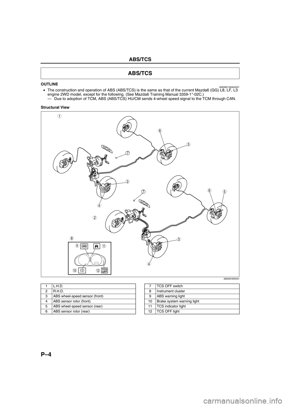
OUTLINEA6E692146444201•The construction and operation of ABS (ABS/TCS) is the same as that of the current Mazda6 (GG) L8, LF, L3
engine 2WD model, except for the following. (See Mazda6 Training Manual 3359-1*-02C.)
—Due to adoption of TCM, ABS (ABS/TCS) HU/CM sends 4-wheel speed signal to the TCM through CAN.
Structural View
.
ABS/TCS
5
3
1
2
6
7
5
3
6
8
4
4
7
9
10TCS
OFF
11
12
A6E6916W201
1 L.H.D.
2 R.H.D.
3 ABS wheel-speed sensor (front)
4 ABS sensor rotor (front)
5 ABS wheel-speed sensor (rear)
6 ABS sensor rotor (rear)7 TCS OFF switch
8 Instrument cluster
9 ABS warning light
10 Brake system warning light
11 TCS indicator light
12 TCS OFF light