light MAZDA 6 2002 Workshop Manual Suplement
[x] Cancel search | Manufacturer: MAZDA, Model Year: 2002, Model line: 6, Model: MAZDA 6 2002Pages: 909, PDF Size: 17.16 MB
Page 608 of 909
TROUBLESHOOTING
K2–193
K2
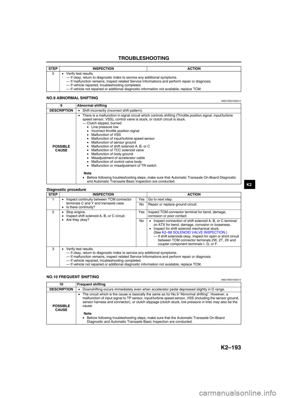
End Of SieNO.9 ABNORMAL SHIFTINGA6E578001030212
Diagnostic procedure
End Of Sie
NO.10 FREQUENT SHIFTINGA6E578001030213
End Of Sie
5•Verify test results.
—If okay, return to diagnostic index to service any additional symptoms.
—If malfunction remains, inspect related Service Informations and perform repair or diagnosis.
—If vehicle repaired, troubleshooting completed.
—If vehicle not repaired or additional diagnostic information not available, replace TCM. STEP INSPECTION ACTION
9 Abnormal shifting
DESCRIPTION•Shift incorrectly (incorrect shift pattern).
POSSIBLE
CAUSE•There is a malfunction in signal circuit which controls shifting (Throttle position signal, input/turbine
speed sensor, VSS), control valve is stuck, or clutch circuit is stuck.
—Clutch slipped, burned
•Line pressure low
•Incorrect throttle position signal
•Malfunction of VSS
•Malfunction of input/turbine speed sensor
•Malfunction of sensor ground
•Malfunction of shift solenoid A, B, or C
•Malfunction of TCC solenoid valve
•Malfunction of body ground
•Misadjustment of accelerator cable
•Malfunction of control valve body
•Malfunction or misadjustment of TR switch
Note
•Before following troubleshooting steps, make sure that Automatic Transaxle On-Board Diagnostic
and Automatic Transaxle Basic Inspection are conducted.
STEP INSPECTION ACTION
1•Inspect continuity between TCM connector
terminals C and Y and transaxle case.
•Is there continuity?Yes Go to next step.
No Repair or replace ground circuit.
2•Stop engine.
•Inspect shift solenoid A, B, or C circuit.
•Are they okay?Yes Inspect TCM connector terminal for bend, damage,
corrosion or poor contact.
No•Inspect connection of shift solenoid A, B, or C terminal
on ATX for bend, damage, corrosion or looseness.
•Inspect for shift solenoid mechanical stuck.
(See K2–88 SOLENOID VALVE INSPECTION.)
—If shift solenoids okay, inspect for open or short circuit
between TCM connector terminals 2W, 2T, 2X and
coupler component terminals I, G, or F.
3•Verify test results.
—If okay, return to diagnostic index to service any additional symptoms.
—If malfunction remains, inspect related Service Informations and perform repair or diagnosis.
—If vehicle repaired, troubleshooting completed.
—If vehicle not repaired or additional diagnostic information not available, replace TCM.
10 Frequent shifting
DESCRIPTION•Downshifting occurs immediately even when accelerator pedal depressed slightly in D range.
POSSIBLE
CAUSE•The circuit which is the cause is basically the same as for No.9 “Abnormal shifting”. However, a
malfunction of input signal to TP sensor, input/turbine speed sensor, VSS (including the sensor ground,
sensor harness and connector), or clutch slippage (clutch stuck, low pressure in line) may also be the
cause.
Note
•Before following troubleshooting steps, make sure that the Automatic Transaxle On-Board
Diagnostic and Automatic Transaxle Basic Inspection are conducted.
Page 609 of 909

K2–194
TROUBLESHOOTING
NO.11 SHIFT POINT IS HIGH OR LOWA6E578001030214
End Of SieNO.12 TORQUE CONVERTER CLUTCH (TCC) NON-OPERATIONA6E578001030215
Diagnostic procedure
11 Shift point is high or low
DESCRIPTION•Shift point considerably different from automatic shift diagram.
•Shift delays when accelerating.
•Shift occurs quickly when accelerating and engine speed does not increase.
POSSIBLE
CAUSE•If the transaxle does not shift abnormally, there is a malfunction of input signal to TP sensor, input/
turbine speed sensor, or VSS.
•If engine speed is high or low regardless that shifting is normal, inspect tachometer.
•Verify that output signal of TP sensor changes linearly.
Note
•Before following troubleshooting steps, make sure that Automatic Transaxle On-Board Diagnostic
and Automatic Transaxle Basic Inspection are conducted.
12 Torque converter clutch (TCC) non-operation
DESCRIPTION•TCC does not operate when vehicle reaches TCC operation range.
POSSIBLE
CAUSE•Basically, TCC does not operate when fail-safe is operating. Verify DTC at first. If TCC operates when
driving at high speeds only, the malfunction (improper adjustment) is in D and/or M ranges switch circuit
or TR switch circuit.
Note
•If the TCC or piston is stuck, inspect them. In addition, inspect the oil cooler for foreign particles
which may have mixed in with the ATF.
•TCC piston slipped, burned
—Line pressure low
•Incorrect throttle position signal
•Input/turbine speed sensor malfunction
•TFT sensor malfunction
•Sensor ground malfunction
•VSS malfunction
•Malfunction of output solenoid valve system (Sticking)
•TCC solenoid valve malfunction
•Malfunction of control valve body system (Poor operation, sticking)
•TCC piston hydraulic pressure system malfunction
•Malfunction of TP sensor (Not operating linearly)
•Malfunction of input/turbine speed sensor or VSS
Note
•Before following troubleshooting steps, make sure that Automatic Transaxle On-Board Diagnostic
and Automatic Transaxle Basic Inspection are conducted.
STEP INSPECTION ACTION
1•Turn ignition switch to ON.
•Does gear position lamp indication
correspond to selector lever position?Yes Go to next step.
No Go to symptom troubleshooting No.27 “Gear position
indicator light does not illuminate in M range”, or No.28
“Gear position indicator light illuminates in D range or P, N,
R positions”.
2•Disconnect TCM.
•Is resistance between ground terminals 1C,
1Y at TCM connector and body ground less
than 5.0 ohm?Yes Go to next step.
No Repair open ground circuit.
3•Remove torque converter.
•Inspect torque converter.
(See ATX Workshop Manual.)
•Is torque converter okay?Yes•Overhaul control valve body and repair or replace any
defective parts.
(See ATX Workshop Manual.)
•If problem remains, replace or overhaul transaxle and
repair or replace any defective parts.
(See ATX Workshop Manual.)
No•Replace torque converter.
4•Verify test results.
—If okay, return to diagnostic index to service any additional symptoms.
—If malfunction remains, inspect related Service Informations and perform repair or diagnosis.
—If vehicle repaired, troubleshooting completed.
—If vehicle not repaired or additional diagnostic information not available, replace TCM.
Page 615 of 909
K2–200
TROUBLESHOOTING
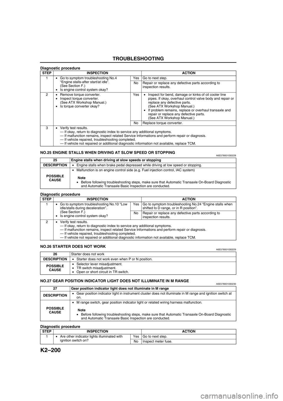
Diagnostic procedure
End Of SieNO.25 ENGINE STALLS WHEN DRIVING AT SLOW SPEED OR STOPPINGA6E578001030228
Diagnostic procedure
End Of SieNO.26 STARTER DOES NOT WORKA6E578001030229
End Of SieNO.27 GEAR POSITION INDICATOR LIGHT DOES NOT ILLUMINATE IN M RANGEA6E578001030230
Diagnostic procedure
STEP INSPECTION ACTION
1•Go to symptom troubleshooting No.4
“Engine stalls-after start/at idle”.
(See Section F.)
•Is engine control system okay?Yes Go to next step.
No Repair or replace any defective parts according to
inspection results.
2•Remove torque converter.
•Inspect torque converter.
(See ATX Workshop Manual.)
•Is torque converter okay?Yes•Inspect for bend, damage or kinks of oil cooler line
pipes. If okay, overhaul control valve body and repair or
replace any defective parts.
(See ATX Workshop Manual.)
•If problem remains, replace or overhaul transaxle and
repair or replace any defective parts.
(See ATX Workshop Manual.)
No Replace torque converter.
3•Verify test results.
—If okay, return to diagnostic index to service any additional symptoms.
—If malfunction remains, inspect related Service Informations and perform repair or diagnosis.
—If vehicle repaired, troubleshooting completed.
—If vehicle not repaired or additional diagnostic information not available, replace TCM.
25 Engine stalls when driving at slow speeds or stopping
DESCRIPTION•Engine stalls when brake pedal depressed while driving at low speed or stopping.
POSSIBLE
CAUSE•Malfunction is on engine control side (e.g. Fuel injection control, IAC system)
Note
•Before following troubleshooting steps, make sure that Automatic Transaxle On-Board Diagnostic
and Automatic Transaxle Basic Inspection are conducted.
STEP INSPECTION ACTION
1•Go to symptom troubleshooting No.10 “Low
idle/stalls during deceleration”.
(See Section F.)
•Is engine control system okay?Yes Go to symptom troubleshooting No.24 “Engine stalls when
shifted to D range, or in R position”.
No Repair or replace any defective parts according to
inspection results.
2•Verify test results.
—If okay, return to diagnostic index to service any additional symptoms.
—If malfunction remains, inspect related Service Informations and perform repair or diagnosis.
—If vehicle repaired, troubleshooting completed.
—If vehicle not repaired or additional diagnostic information not available, replace TCM.
26Starter does not work
DESCRIPTION•Starter does not work even when P or N position.
POSSIBLE
CAUSE•Selector lever misadjustment.
•TR switch misadjustment.
•Open or short circuit in TR switch.
27 Gear position indicator light does not illuminate in M range
DESCRIPTION•Gear position indicator light in instrument cluster does not illuminate in M range and ignition switch at
on.
POSSIBLE
CAUSE•M range switch, gear position indicator light or related wiring harness malfunction.
Note
•Before following troubleshooting steps, make sure that Automatic Transaxle On-Board Diagnostic
and Automatic Transaxle Basic Inspection are conducted.
STEP INSPECTION ACTION
1•Are other indicator lights illuminated with
ignition switch on? Yes Go to next step.
No Inspect meter fuse.
Page 616 of 909
TROUBLESHOOTING
K2–201
K2
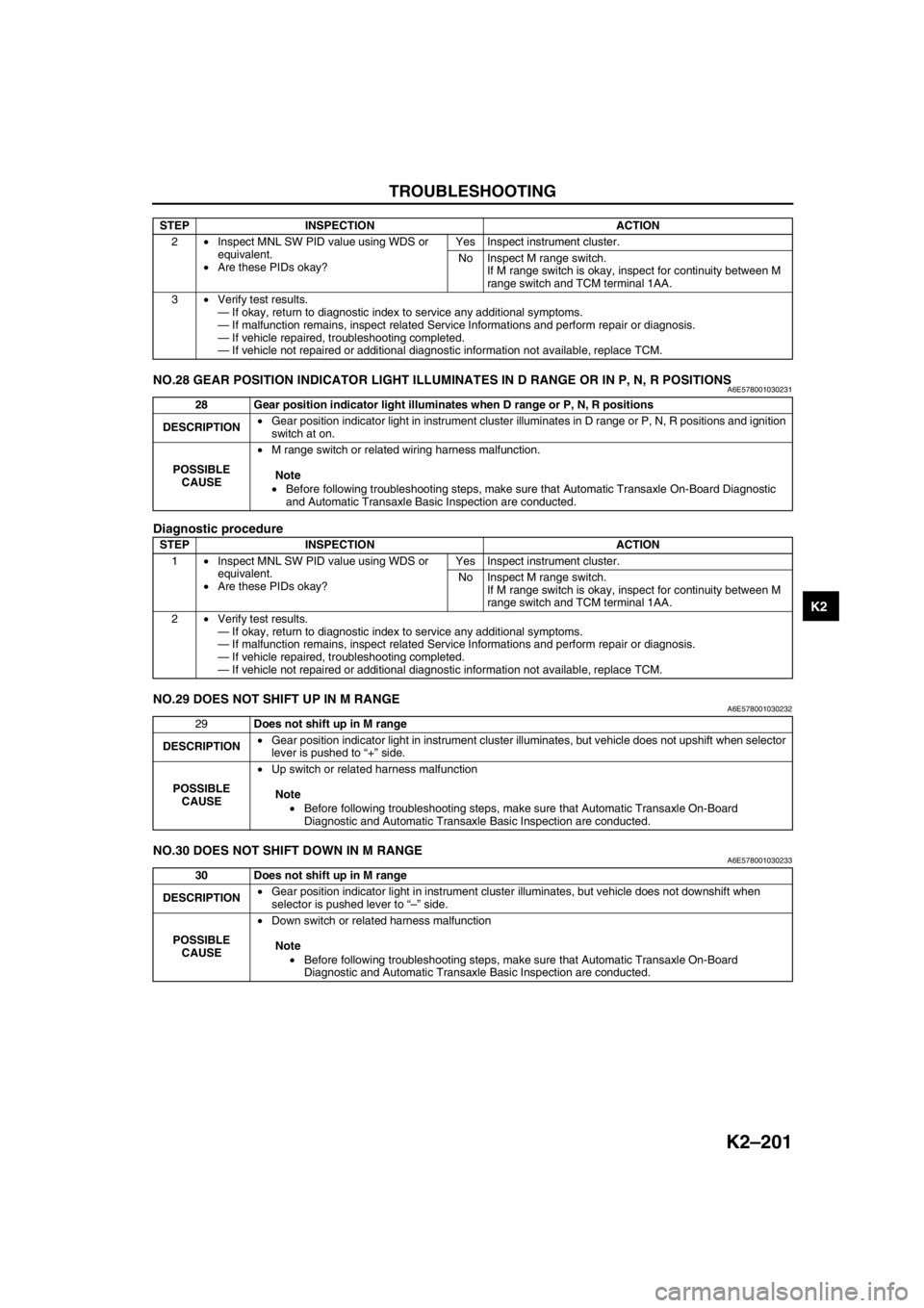
End Of SieNO.28 GEAR POSITION INDICATOR LIGHT ILLUMINATES IN D RANGE OR IN P, N, R POSITIONSA6E578001030231
Diagnostic procedure
End Of SieNO.29 DOES NOT SHIFT UP IN M RANGEA6E578001030232
End Of SieNO.30 DOES NOT SHIFT DOWN IN M RANGEA6E578001030233
End Of Sie
2•Inspect MNL SW PID value using WDS or
equivalent.
•Are these PIDs okay?Yes Inspect instrument cluster.
No Inspect M range switch.
If M range switch is okay, inspect for continuity between M
range switch and TCM terminal 1AA.
3•Verify test results.
—If okay, return to diagnostic index to service any additional symptoms.
—If malfunction remains, inspect related Service Informations and perform repair or diagnosis.
—If vehicle repaired, troubleshooting completed.
—If vehicle not repaired or additional diagnostic information not available, replace TCM. STEP INSPECTION ACTION
28 Gear position indicator light illuminates when D range or P, N, R positions
DESCRIPTION•Gear position indicator light in instrument cluster illuminates in D range or P, N, R positions and ignition
switch at on.
POSSIBLE
CAUSE•M range switch or related wiring harness malfunction.
Note
•Before following troubleshooting steps, make sure that Automatic Transaxle On-Board Diagnostic
and Automatic Transaxle Basic Inspection are conducted.
STEP INSPECTION ACTION
1•Inspect MNL SW PID value using WDS or
equivalent.
•Are these PIDs okay?Yes Inspect instrument cluster.
No Inspect M range switch.
If M range switch is okay, inspect for continuity between M
range switch and TCM terminal 1AA.
2•Verify test results.
—If okay, return to diagnostic index to service any additional symptoms.
—If malfunction remains, inspect related Service Informations and perform repair or diagnosis.
—If vehicle repaired, troubleshooting completed.
—If vehicle not repaired or additional diagnostic information not available, replace TCM.
29Does not shift up in M range
DESCRIPTION•Gear position indicator light in instrument cluster illuminates, but vehicle does not upshift when selector
lever is pushed to “+” side.
POSSIBLE
CAUSE•Up switch or related harness malfunction
Note
•Before following troubleshooting steps, make sure that Automatic Transaxle On-Board
Diagnostic and Automatic Transaxle Basic Inspection are conducted.
30 Does not shift up in M range
DESCRIPTION•Gear position indicator light in instrument cluster illuminates, but vehicle does not downshift when
selector is pushed lever to “–” side.
POSSIBLE
CAUSE•Down switch or related harness malfunction
Note
•Before following troubleshooting steps, make sure that Automatic Transaxle On-Board
Diagnostic and Automatic Transaxle Basic Inspection are conducted.
Page 629 of 909
PROPELLER SHAFT
L–13
L
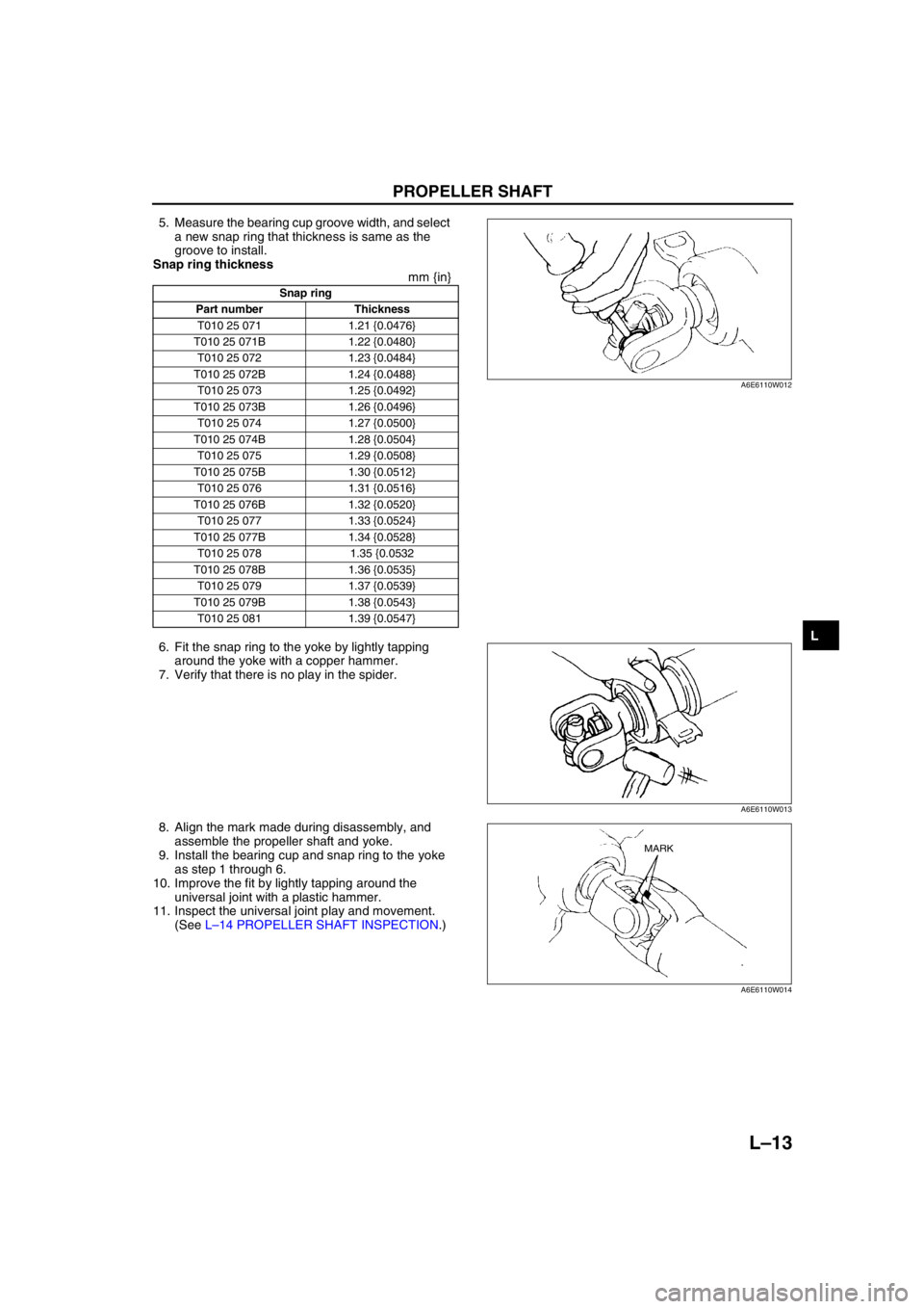
5. Measure the bearing cup groove width, and select
a new snap ring that thickness is same as the
groove to install.
Snap ring thickness
mm {in}
6. Fit the snap ring to the yoke by lightly tapping
around the yoke with a copper hammer.
7. Verify that there is no play in the spider.
8. Align the mark made during disassembly, and
assemble the propeller shaft and yoke.
9. Install the bearing cup and snap ring to the yoke
as step 1 through 6.
10. Improve the fit by lightly tapping around the
universal joint with a plastic hammer.
11. Inspect the universal joint play and movement.
(See L–14 PROPELLER SHAFT INSPECTION.)
End Of Sie
Snap ring
Part number Thickness
T010 25 071 1.21 {0.0476}
T010 25 071B 1.22 {0.0480}
T010 25 072 1.23 {0.0484}
T010 25 072B 1.24 {0.0488}
T010 25 073 1.25 {0.0492}
T010 25 073B 1.26 {0.0496}
T010 25 074 1.27 {0.0500}
T010 25 074B 1.28 {0.0504}
T010 25 075 1.29 {0.0508}
T010 25 075B 1.30 {0.0512}
T010 25 076 1.31 {0.0516}
T010 25 076B 1.32 {0.0520}
T010 25 077 1.33 {0.0524}
T010 25 077B 1.34 {0.0528}
T010 25 078 1.35 {0.0532
T010 25 078B 1.36 {0.0535}
T010 25 079 1.37 {0.0539}
T010 25 079B 1.38 {0.0543}
T010 25 081 1.39 {0.0547}
A6E6110W012
A6E6110W013
MARK
A6E6110W014
Page 631 of 909
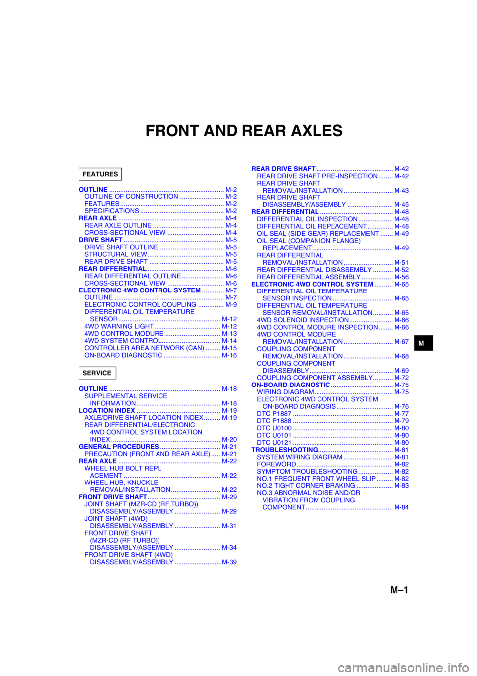
M–1
M
MFRONT AND REAR AXLES
OUTLINE............................................................... M-2
OUTLINE OF CONSTRUCTION ........................ M-2
FEATURES ......................................................... M-2
SPECIFICATIONS .............................................. M-2
REAR AXLE.......................................................... M-4
REAR AXLE OUTLINE ....................................... M-4
CROSS-SECTIONAL VIEW ............................... M-4
DRIVE SHAFT....................................................... M-5
DRIVE SHAFT OUTLINE.................................... M-5
STRUCTURAL VIEW.......................................... M-5
REAR DRIVE SHAFT ......................................... M-5
REAR DIFFERENTIAL.......................................... M-6
REAR DIFFERENTIAL OUTLINE ....................... M-6
CROSS-SECTIONAL VIEW ............................... M-6
ELECTRONIC 4WD CONTROL SYSTEM............ M-7
OUTLINE ............................................................ M-7
ELECTRONIC CONTROL COUPLING .............. M-9
DIFFERENTIAL OIL TEMPERATURE
SENSOR ........................................................ M-12
4WD WARNING LIGHT .................................... M-12
4WD CONTROL MODURE .............................. M-13
4WD SYSTEM CONTROL................................ M-14
CONTROLLER AREA NETWORK (CAN) ........ M-15
ON-BOARD DIAGNOSTIC ............................... M-16
OUTLINE............................................................. M-18
SUPPLEMENTAL SERVICE
INFORMATION .............................................. M-18
LOCATION INDEX.............................................. M-19
AXLE/DRIVE SHAFT LOCATION INDEX ......... M-19
REAR DIFFERENTIAL/ELECTRONIC
4WD CONTROL SYSTEM LOCATION
INDEX ............................................................ M-20
GENERAL PROCEDURES................................. M-21
PRECAUTION (FRONT AND REAR AXLE) ..... M-21
REAR AXLE........................................................ M-22
WHEEL HUB BOLT REPL
ACEMENT ..................................................... M-22
WHEEL HUB, KNUCKLE
REMOVAL/INSTALLATION ........................... M-22
FRONT DRIVE SHAFT........................................ M-29
JOINT SHAFT (MZR-CD (RF TURBO))
DISASSEMBLY/ASSEMBLY ......................... M-29
JOINT SHAFT (4WD)
DISASSEMBLY/ASSEMBLY ......................... M-31
FRONT DRIVE SHAFT
(MZR-CD (RF TURBO))
DISASSEMBLY/ASSEMBLY ......................... M-34
FRONT DRIVE SHAFT (4WD)
DISASSEMBLY/ASSEMBLY ......................... M-39REAR DRIVE SHAFT.......................................... M-42
REAR DRIVE SHAFT PRE-INSPECTION ........ M-42
REAR DRIVE SHAFT
REMOVAL/INSTALLATION ........................... M-43
REAR DRIVE SHAFT
DISASSEMBLY/ASSEMBLY ......................... M-45
REAR DIFFERENTIAL........................................ M-48
DIFFERENTIAL OIL INSPECTION ................... M-48
DIFFERENTIAL OIL REPLACEMENT .............. M-48
OIL SEAL (SIDE GEAR) REPLACEMENT ....... M-49
OIL SEAL (COMPANION FLANGE)
REPLACEMENT ............................................ M-49
REAR DIFFERENTIAL
REMOVAL/INSTALLATION ........................... M-51
REAR DIFFERENTIAL DISASSEMBLY ........... M-52
REAR DIFFERENTIAL ASSEMBLY ................. M-56
ELECTRONIC 4WD CONTROL SYSTEM.......... M-65
DIFFERENTIAL OIL TEMPERATURE
SENSOR INSPECTION ................................. M-65
DIFFERENTIAL OIL TEMPERATURE
SENSOR REMOVAL/INSTALLATION ........... M-65
4WD SOLENOID INSPECTION........................ M-66
4WD CONTROL MODURE INSPECTION ........ M-66
4WD CONTROL MODURE
REMOVAL/INSTALLATION ........................... M-67
COUPLING COMPONENT
REMOVAL/INSTALLATION ........................... M-68
COUPLING COMPONENT
DISASSEMBLY .............................................. M-69
COUPLING COMPONENT ASSEMBLY........... M-72
ON-BOARD DIAGNOSTIC.................................. M-75
WIRING DIAGRAM ........................................... M-75
ELECTRONIC 4WD CONTROL SYSTEM
ON-BOARD DIAGNOSIS ............................... M-76
DTC P1887 ....................................................... M-77
DTC P1888 ....................................................... M-79
DTC U0100 ....................................................... M-80
DTC U0101 ....................................................... M-80
DTC U0121 ....................................................... M-80
TROUBLESHOOTING......................................... M-81
SYSTEM WIRING DIAGRAM ........................... M-81
FOREWORD ..................................................... M-82
SYMPTOM TROUBLESHOOTING ................... M-82
NO.1 FREQUENT FRONT WHEEL SLIP ......... M-82
NO.2 TIGHT CORNER BRAKING .................... M-83
NO.3 ABNORMAL NOISE AND/OR
VIBRATION FROM COUPLING
COMPONENT ................................................ M-84 FEATURES
SERVICE
Page 637 of 909
ELECTRONIC 4WD CONTROL SYSTEM
M–7
M
OUTLINEA6E632227100201Features
Improved off-road mobility, handling stability, operability, fuel economy and marketability
•An electronic 4WD control system, which automatically optimizes traction distribution to the front and rear
wheels, has been adopted.
Improved serviceability
•A self-diagnostic function has been adopted for the electronic 4WD control system.
Electronic 4WD control system outline
•The newly adopted electronic 4WD control system automatically and optimally controls drive torque distribution
for the front and rear wheels. Due to this off-road mobility, driving stability and fuel economy are improved.
•Based on the input signals from each sensor, the 4WD control modure (4WD CM) determines vehicle driving
and road conditions, and controls output current to the electronic control coupling (4WD solenoid) inside the
rear differential. This control allows for optimal distribution of the drive torque from the engine to the rear
wheels.
•Also, the 4WD CM automatically controls the 4WD, greatly reducing the load on the driver and improving
operability.
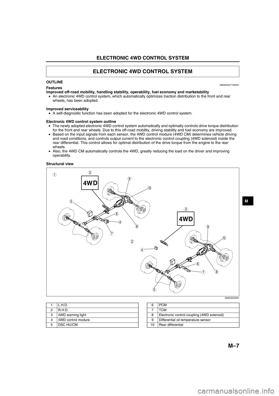
Structural view
.
ELECTRONIC 4WD CONTROL SYSTEM
87
5
4
3
6
9
8
7
5
4
3
10
6
1
2
9
10
A6E63222001
1L.H.D.
2 R.H.D.
3 4WD warning light
4 4WD control modure
5 DSC HU/CM6PCM
7TCM
8 Electronic control coupling (4WD solenoid)
9 Differential oil temperature sensor
10 Rear differential
Page 638 of 909
M–8
ELECTRONIC 4WD CONTROL SYSTEM
Components and Functions
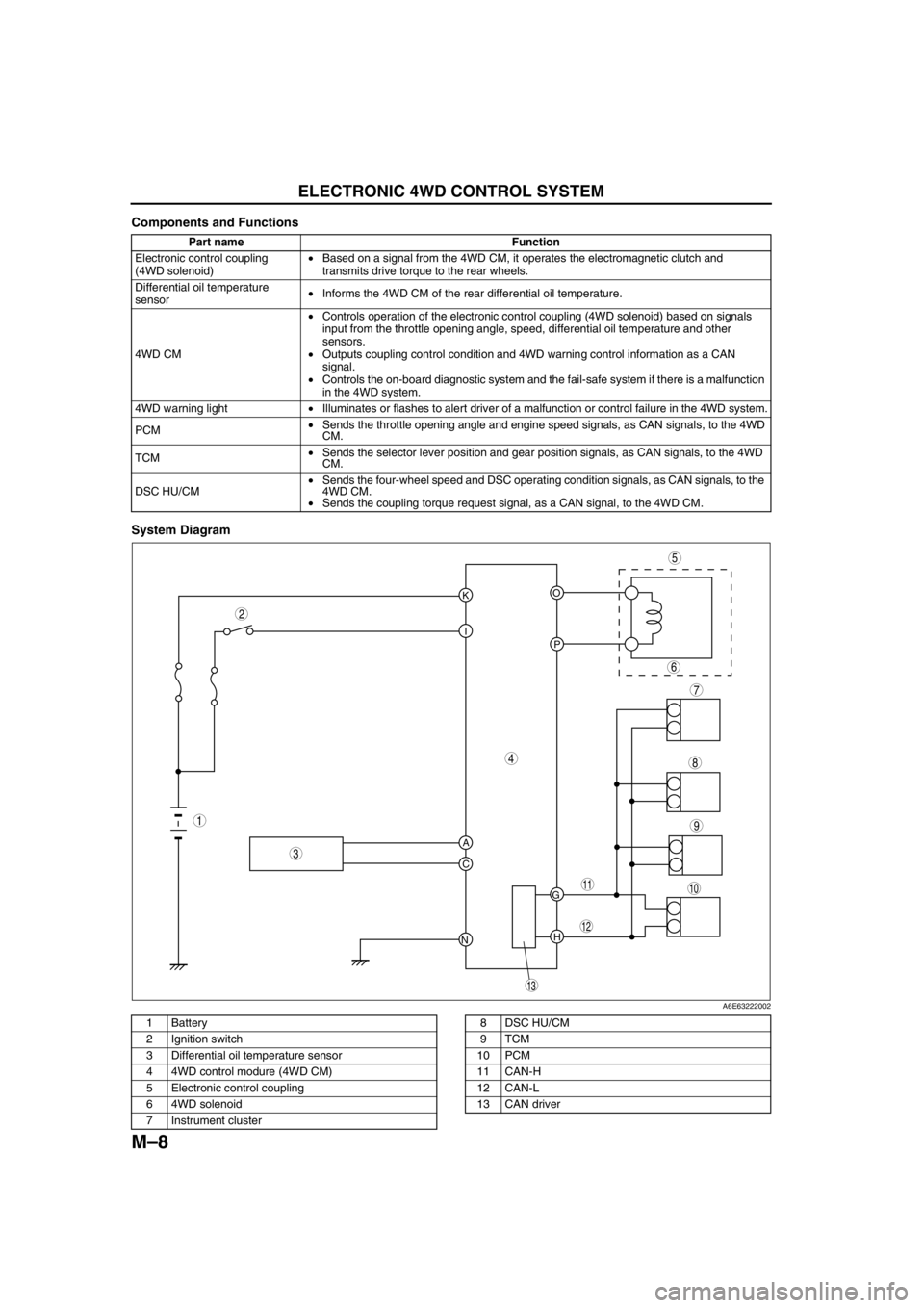
System Diagram
.
Part name Function
Electronic control coupling
(4WD solenoid)•Based on a signal from the 4WD CM, it operates the electromagnetic clutch and
transmits drive torque to the rear wheels.
Differential oil temperature
sensor•Informs the 4WD CM of the rear differential oil temperature.
4WD CM•Controls operation of the electronic control coupling (4WD solenoid) based on signals
input from the throttle opening angle, speed, differential oil temperature and other
sensors.
•Outputs coupling control condition and 4WD warning control information as a CAN
signal.
•Controls the on-board diagnostic system and the fail-safe system if there is a malfunction
in the 4WD system.
4WD warning light•Illuminates or flashes to alert driver of a malfunction or control failure in the 4WD system.
PCM•Sends the throttle opening angle and engine speed signals, as CAN signals, to the 4WD
CM.
TCM•Sends the selector lever position and gear position signals, as CAN signals, to the 4WD
CM.
DSC HU/CM•Sends the four-wheel speed and DSC operating condition signals, as CAN signals, to the
4WD CM.
•Sends the coupling torque request signal, as a CAN signal, to the 4WD CM.
KO
P I
A
C
NH G
9
8
7
5
4
3
10
13
11
12
6
1
2
A6E63222002
1 Battery
2 Ignition switch
3 Differential oil temperature sensor
4 4WD control modure (4WD CM)
5 Electronic control coupling
6 4WD solenoid
7 Instrument cluster8 DSC HU/CM
9TCM
10 PCM
11 CAN-H
12 CAN-L
13 CAN driver
Page 642 of 909
M–12
ELECTRONIC 4WD CONTROL SYSTEM
DIFFERENTIAL OIL TEMPERATURE SENSORA6E632227100203Function
•The differential oil temperature sensor detects the rear differential oil temperature based on the resistance of
the thermistor, and inputs it to the 4WD control modure (4WD CM).
Construction/Operation
•The differential oil temperature sensor is installed in the rear differential carrier.
•The differential oil temperature sensor uses a thermistor whose resistance changes according to changes in
the rear differential oil temperature.
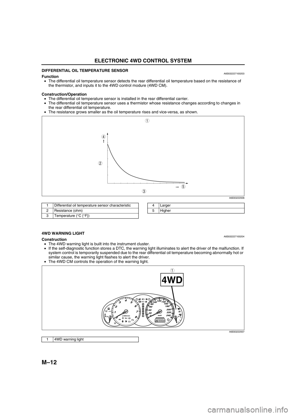
•The resistance grows smaller as the oil temperature rises and vice-versa, as shown.
.
End Of Sie
4WD WARNING LIGHTA6E632227100204Construction
•The 4WD warning light is built into the instrument cluster.
•If the self-diagnostic function stores a DTC, the warning light illuminates to alert the driver of the malfunction. If
system control is temporarily suspended due to the rear differential oil temperature becoming abnormally hot or
similar cause, the warning light flashes to alert the driver.
•The 4WD CM controls the operation of the warning light.
.
End Of Sie
5
4
3
1
2
A6E63222006
1 Differential oil temperature sensor characteristic
2 Resistance (ohm)
3 Temperature (°C {°F})4 Larger
5 Higher
1
A6E63222007
1 4WD warning light
Page 643 of 909
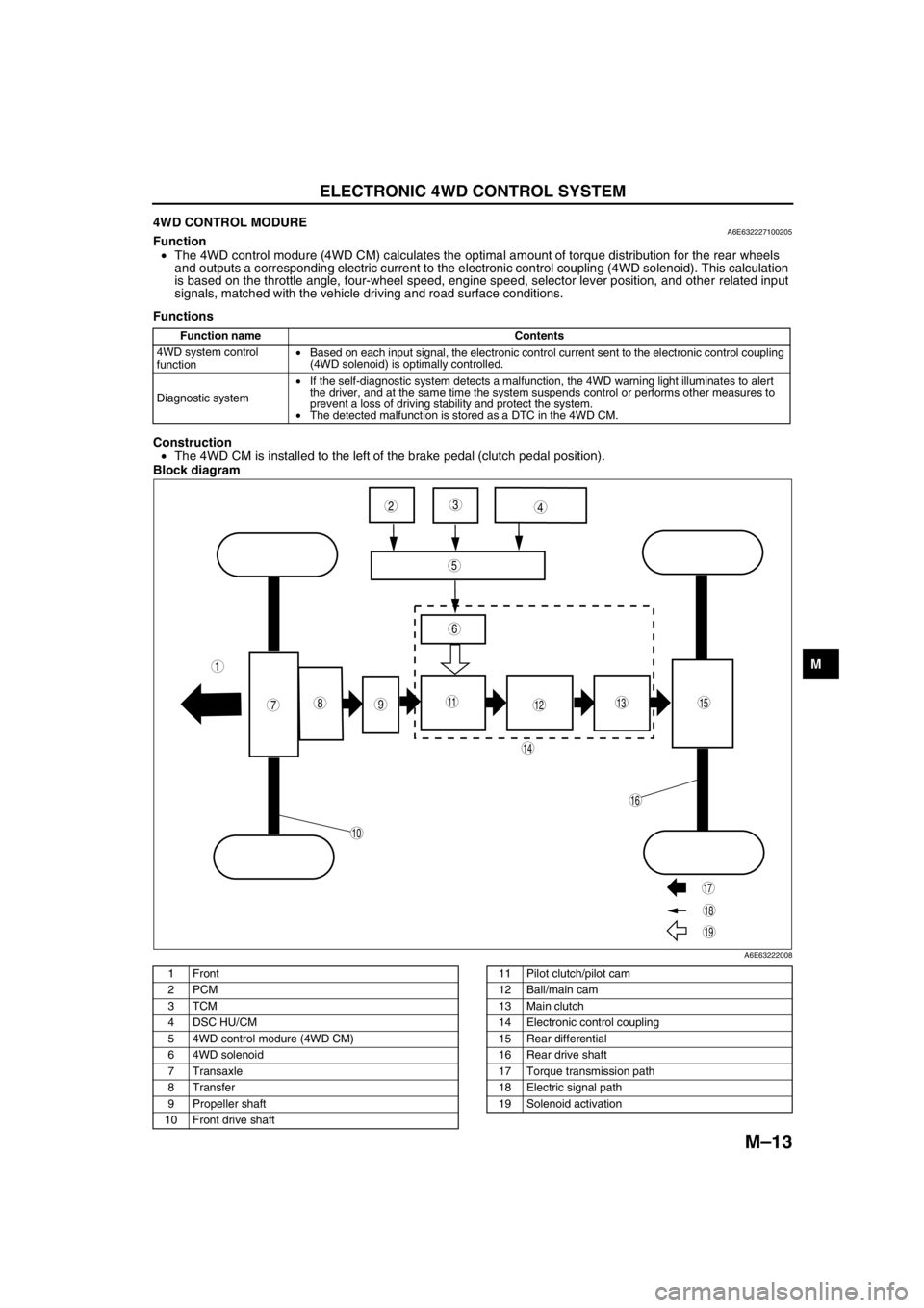
ELECTRONIC 4WD CONTROL SYSTEM
M–13
M
4WD CONTROL MODUREA6E632227100205Function
•The 4WD control modure (4WD CM) calculates the optimal amount of torque distribution for the rear wheels
and outputs a corresponding electric current to the electronic control coupling (4WD solenoid). This calculation
is based on the throttle angle, four-wheel speed, engine speed, selector lever position, and other related input
signals, matched with the vehicle driving and road surface conditions.
Functions
Construction
•The 4WD CM is installed to the left of the brake pedal (clutch pedal position).
Block diagram
.
Function name Contents
4WD system control
function•Based on each input signal, the electronic control current sent to the electronic control coupling
(4WD solenoid) is optimally controlled.
Diagnostic system•If the self-diagnostic system detects a malfunction, the 4WD warning light illuminates to alert
the driver, and at the same time the system suspends control or performs other measures to
prevent a loss of driving stability and protect the system.
•The detected malfunction is stored as a DTC in the 4WD CM.
987
5
43
10
19
18
17
15
16
14
131112
6
1
2
A6E63222008
1Front
2PCM
3TCM
4 DSC HU/CM
5 4WD control modure (4WD CM)
6 4WD solenoid
7Transaxle
8Transfer
9 Propeller shaft
10 Front drive shaft11 Pilot clutch/pilot cam
12 Ball/main cam
13 Main clutch
14 Electronic control coupling
15 Rear differential
16 Rear drive shaft
17 Torque transmission path
18 Electric signal path
19 Solenoid activation