sensor MAZDA 6 2002 Workshop Manual Suplement
[x] Cancel search | Manufacturer: MAZDA, Model Year: 2002, Model line: 6, Model: MAZDA 6 2002Pages: 909, PDF Size: 17.16 MB
Page 427 of 909

K2–12
AUTOMATIC TRANSAXLE
Electronic Control Item and Control
Component Description (Electronic Control)
Control item Contents
Shift control•Detects engine load condition and vehicle speed. Shifts to the best gear
position according to the programmed automatic shift diagram.
Line pressure control•Generates line pressure matching the engine load condition and driving
conditions. Optimizes line pressure for each shift. When the ATF
temperature is low, automatically optimizes line pressure for quick clutch
engagement.
Revers inhibition control•When the shift lever is shifted to R position while the vehicle is running
forward at approx. 30 km/h{19 mph} or more, the TCM turns the neutral
shift solenoid valve on and drains the low and reverse brake hydraulic
pressure. Due to this, the transaxle shifts to neutral.
Shift transient control•Adjusts transient hydraulic pressure according to engine load and
vehicle driving conditions when shifting using the pressure control
solenoid, 2-4 brake solenoid valve, the high clutch solenoid valve, and
each accumulator control valve.
•Temporarily lowers engine torque during shift (up and down) to improve
shift feel
•The lock timing for the reduction brake band is controlled by the control
of the reduction timing solenoid valve ON/OFF timing.
•The lock timing for the clutch brake is controlled by the control of shift
solenoid A, B, and C ON/OFF timing.
Feedback control•Corrects clutch engagement pressure and timing on drain side to
compensate for changes in engine performance and changes in
transaxle
TCC control•Controls TCC according to the programmed TCC points
N-D select control•When a driving range is selected from P/N, the fuel injection amount is
controlled to prevent fluctuation in engine speed.
Slope mode control•Changes the shift point to prevent frequent shifting up/down when
climbing hills
OBD system•Detects and/or memorizes failure of input/output part and transaxle
condition
Part name Function
Input system TR switch•Detects selector lever ranges/positions
Input/turbine speed sensor•Detects reverse clutch drum revolution speed
Intermediate sensor•Detects output gear revolution speed
Vehicle speedometer sensor•Detects parking gear revolution speed
TFT sensor•Detects the ATF temperature
Brake switch•Detects the brake pedal depressed
Cruise control module (in cruise actuator)•When the cruise control is in use, the signal detects when the
difference between the target speed and actual speed
exceeds specification
M range switch•Detects selector lever shifted M range
Up switch•Detects up shift in M range
Down switch•Detects down shift in M range
CAN signal Throttle position signal•Input throttle opening angle from PCM
Engine torque signal
(without torque down)•Input engine torque from PCM
Engine torque signal (with
torque down)•Input engine torque from PCM
Engine torque signal (loss
torque)•Input engine loss torque from PCM
Torque reduced signal•Detects signals indicating torque down availability
Engine coolant
temperature signal•Input engine coolant temperature from PCM
Engine speed signal•Input engine speed from PCM
Battery OFF signal•Detect negative battery cable disconnected
4 wheel speed signal•Input wheel speed from ABS HU/CM or DSC HU/CM
Page 428 of 909

AUTOMATIC TRANSAXLE
K2–13
K2
End Of SieAUTOMATIC TRANSAXLE DEVICE RELATIONSHIP CHARTA6E571401030206
Output system ON/OFF
typeShift solenoid A•Switches ON and OFF based on electric signals from the
TCM, changes hydraulic circuit to control shifting
Shift solenoid B•Switches ON and OFF based on electric signals from the
TCM, changes hydraulic circuit to control shifting
Shift solenoid C•Switches ON and OFF based on electric signals from the
TCM, changes hydraulic circuit to control shifting
Reduction timing solenoid
valve•Switches ON and OFF based on electric signals from the
TCM, changes hydraulic circuit to control shifting
Neutral shift solenoid valve•Switches ON and OFF based on electric signals from the
TCM, changes hydraulic circuit to control shifting
Duty type
Pressure control solenoid•Switches ON and OFF based on electric signal (duty signals)
from the TCM adjusts line pressure to match driving
conditions
2-4 brake solenoid valve•Switches ON and OFF based on electric signal (duty signals)
from the TCM adjusts line pressure to match driving
conditions
High clutch solenoid valve•Switch ON and OFF based on electric signal (duty signals)
from the TCM adjusts line pressure to match driving
conditions
TCC solenoid valve•Switch ON and OFF based on electric signal (duty signals)
from the TCM to control TCC
CAN signal Reduce torque signal•Sends signals to the PCM during shifting
Range signal•Output transaxle load condition to PCM
Turbine speed signal•Output turbine speed to PCM
ATF temperature signal•Output ATF high temperature signal to PCM
TCC signal•Output TCC signal to PCM
Racing select signal•Requests fuel cut when selector lever is shifted during racing
MIL indicate request signal•Requests MIL illumination when failure is detected by
diagnosis function
AT warning light request
signal•Requests AT warning light indication when failure is detected
by diagnosis function for ATX Part name Function
ComponentControl item
Shift
controlLine
pressure
controlReverse
inhibition
controlShift
transient
controlFeedbac
k controlTCC
controlN-D
select
controlSlope
mode
controlOBD
system
Input
TR switch XXXXXXX X
Input/turbine
speed sensorX XXXXXX
Intermediate
sensorXXX X
Vehicle
speedometer
sensorXXXXXXXXX
TFT sensor XX XXXX X
Brake switch X X X
Cruise control
module (4GR
inhibit signal)XX
M range switch X X
Up switch X X
Down switch X X
Page 460 of 909
AUTOMATIC TRANSAXLE
K2–45
K2
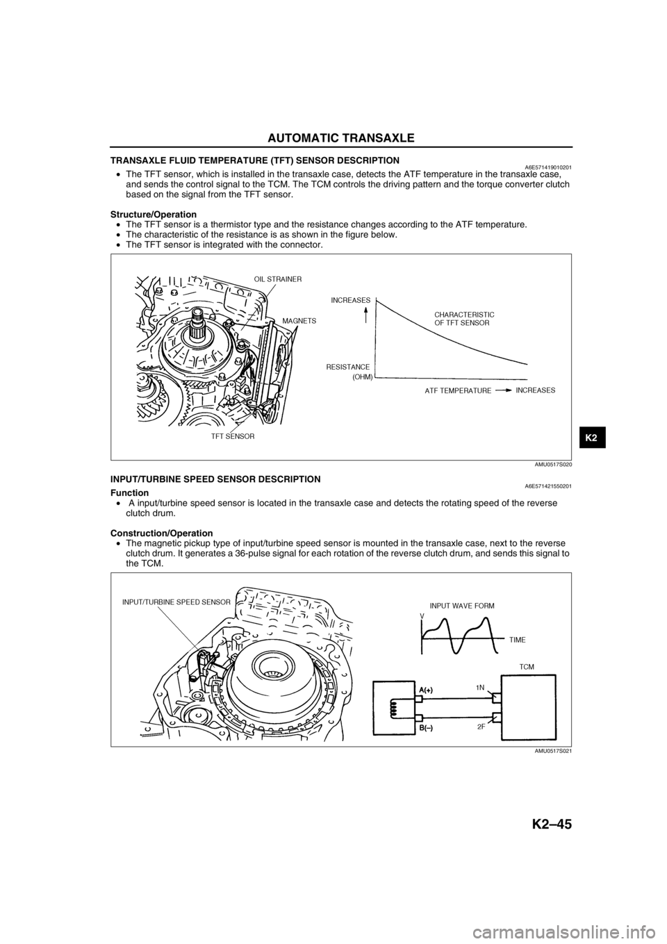
TRANSAXLE FLUID TEMPERATURE (TFT) SENSOR DESCRIPTIONA6E571419010201•The TFT sensor, which is installed in the transaxle case, detects the ATF temperature in the transaxle case,
and sends the control signal to the TCM. The TCM controls the driving pattern and the torque converter clutch
based on the signal from the TFT sensor.
Structure/Operation
•The TFT sensor is a thermistor type and the resistance changes according to the ATF temperature.
•The characteristic of the resistance is as shown in the figure below.
•The TFT sensor is integrated with the connector.
End Of SieINPUT/TURBINE SPEED SENSOR DESCRIPTIONA6E571421550201Function
• A input/turbine speed sensor is located in the transaxle case and detects the rotating speed of the reverse
clutch drum.
Construction/Operation
•The magnetic pickup type of input/turbine speed sensor is mounted in the transaxle case, next to the reverse
clutch drum. It generates a 36-pulse signal for each rotation of the reverse clutch drum, and sends this signal to
the TCM.
End Of Sie
AMU0517S020
AMU0517S021
Page 461 of 909
K2–46
AUTOMATIC TRANSAXLE
INTERMEDIATE SENSOR DESCRIPTIONA6E571419550201Function
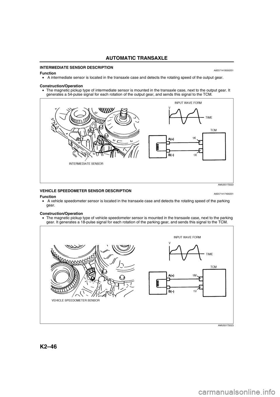
• A intermediate sensor is located in the transaxle case and detects the rotating speed of the output gear.
Construction/Operation
•The magnetic pickup type of intermediate sensor is mounted in the transaxle case, next to the output gear. It
generates a 54-pulse signal for each rotation of the output gear, and sends this signal to the TCM.
End Of SieVEHICLE SPEEDOMETER SENSOR DESCRIPTIONA6E571417400201Function
• A vehicle speedometer sensor is located in the transaxle case and detects the rotating speed of the parking
gear.
Construction/Operation
•The magnetic pickup type of vehicle speedometer sensor is mounted in the transaxle case, next to the parking
gear. It generates a 18-pulse signal for each rotation of the parking gear, and sends this signal to the TCM.
End Of Sie
AMU0517S022
AMU0517S023
Page 466 of 909
AUTOMATIC TRANSAXLE
K2–51
K2
TRANSAXLE CONTROL MODULE (TCM) DESCRIPTIONA6E571418901202Outline
•The TCM controls the automatic transaxle operations. The TCM outputs a control signal to the transaxle
according to the signal from other sensors and/or switches.
•In driving mode, there are three mode selections: NORMAL, high temp, and SLOPE. The TCM automatically
selects the proper mode according to driving condition.
End Of Sie
SHIFT CONTROL DESCRIPTIONA6E571418901203Outline
Features
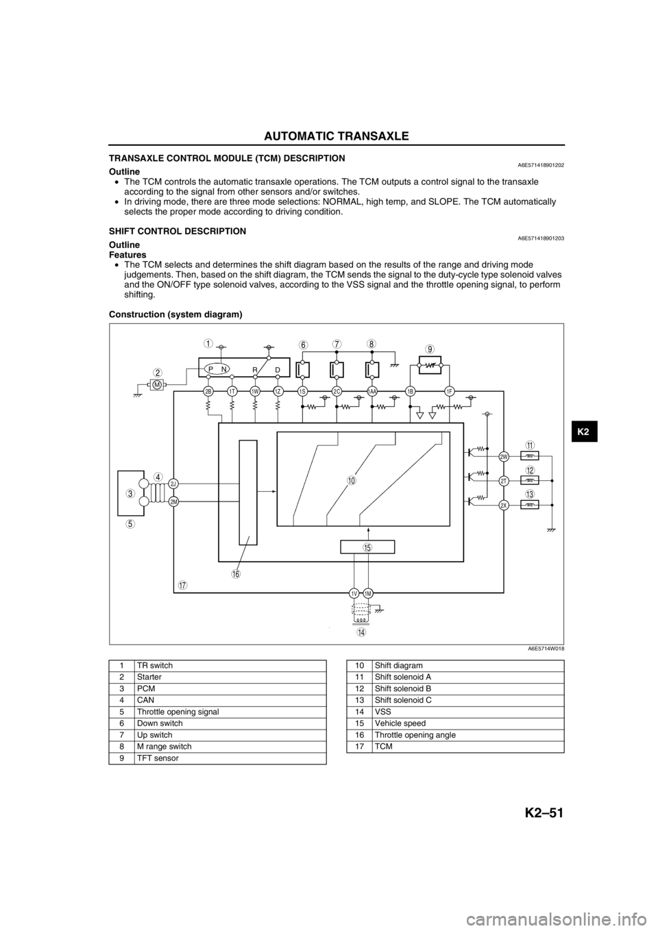
•The TCM selects and determines the shift diagram based on the results of the range and driving mode
judgements. Then, based on the shift diagram, the TCM sends the signal to the duty-cycle type solenoid valves
and the ON/OFF type solenoid valves, according to the VSS signal and the throttle opening signal, to perform
shifting.
Construction (system diagram)
.
2C 2B
2J
2M1AA 1S 1T 1Z1W 1B 1F
2W
1M 1V2T
2X
PN
RD
M
987
5
4
3
1
2
10
17
15
16
14
13
11
12
6
A6E5714W018
1 TR switch
2Starter
3PCM
4CAN
5 Throttle opening signal
6 Down switch
7 Up switch
8 M range switch
9 TFT sensor10 Shift diagram
11 Shift solenoid A
12 Shift solenoid B
13 Shift solenoid C
14 VSS
15 Vehicle speed
16 Throttle opening angle
17 TCM
Page 468 of 909

AUTOMATIC TRANSAXLE
K2–53
K2
Operation
Manual mode shift
•When the selector lever is shifted over from the D to M range position, the M range switch in the selector lever
component turns on, sending a manual mode command signal to the PCM which activates the manual mode
shift control.
•When in manual mode and the selector lever is operated in the back (+) direction, the up switch in the selector
lever component is turned on and an up-shift command signal is inputted to the PCM.
—The PCM, triggered by the up-shift command signal, carries out shifting by outputting an operation signal to
the shift solenoid if the ATF temperature is not low (for 3GR only), vehicle speed is higher than the set
speed and the gear position is 3GR or lower.
•Conversely, when the selector lever is operated in the forward (-) direction, the down switch in the selector lever
component turns on, and a down-shift command signal is inputted to the PCM.
—The PCM, triggered by the down-shift command signal, carries out shifting by outputting an operation
signal to the shift solenoid if the vehicle speed is less than the set speed and the gear position is 2GR or
above.
•The PCM utilizes a specialized M range automatic shift diagram when down shifting. This restriction of manual
downshifting is carried out to reduce load on the ATX and prevent engine over-revving.
13 Instrument cluster
14 Input15 Selector lever component
-M range switch
-Up switch
-Down switch
16 TR switch
17 ABS HU/CM or DSC HU/CM
18 TFT sensor
Condition Shift control Note
2GR→3GR up-shift command
at low speed•To reduce load on the ATX, upshifting is
inhibited until vehicle reaches speed
possible for upshifting
— 3GR→4GR up-shift command
at low speed
3GR→4GR up-shift command,
low ATF temperature•To reduce load on the ATX, upshifting to
4GR is inhibited
4GR→3GR down-shift
command, above set speed•To prevent engine over-rev, downshifting is
inhibited until vehicle reaches speed
possible for downshifting•Selector indicator “M” light and gear
position indicator light flash to alert
driver
3GR→2GR down-shift
command, above set speed
2GR→1GR down-shift
command, above set speed
In 4GR deceleration, speed
goes below coast-down set
speed (deceleration down-
shift)•To assure drive stability, automatically
downshifts from 4GR to 3GR
— In 3GR deceleration, speed
goes below coast-down set
speed (deceleration down-
shift)•To assure drive stability, automatically
downshifts from 3GR to 1GR
In 2GR deceleration, speed
goes below coast-down set
speed (deceleration down-
shift)•To assure driving stability, automatically
downshifts from 2GR to 1GR
Page 470 of 909
AUTOMATIC TRANSAXLE
K2–55
K2
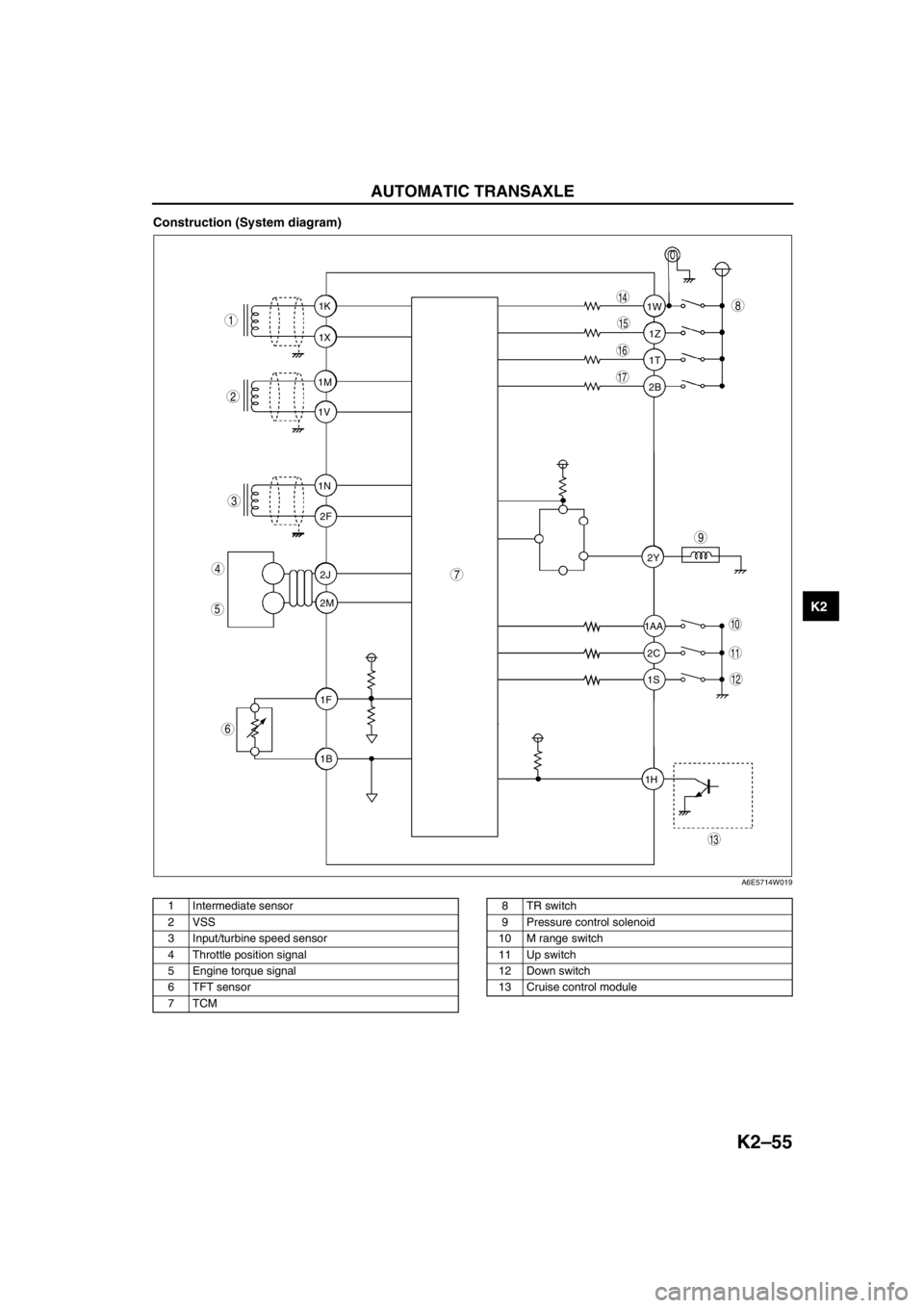
Construction (System diagram)
.
1T 1Z 1W
1AA
2C 2Y
1S
1H2B 1K
1X
1M
1V
1N
2F
2J
2M
1F
1B
9
8
7
5
4
3
1
2
10
17
15
16
14
13
11
12
6
A6E5714W019
1 Intermediate sensor
2 VSS
3 Input/turbine speed sensor
4 Throttle position signal
5 Engine torque signal
6 TFT sensor
7TCM8TR switch
9 Pressure control solenoid
10 M range switch
11 Up switch
12 Down switch
13 Cruise control module
Page 473 of 909
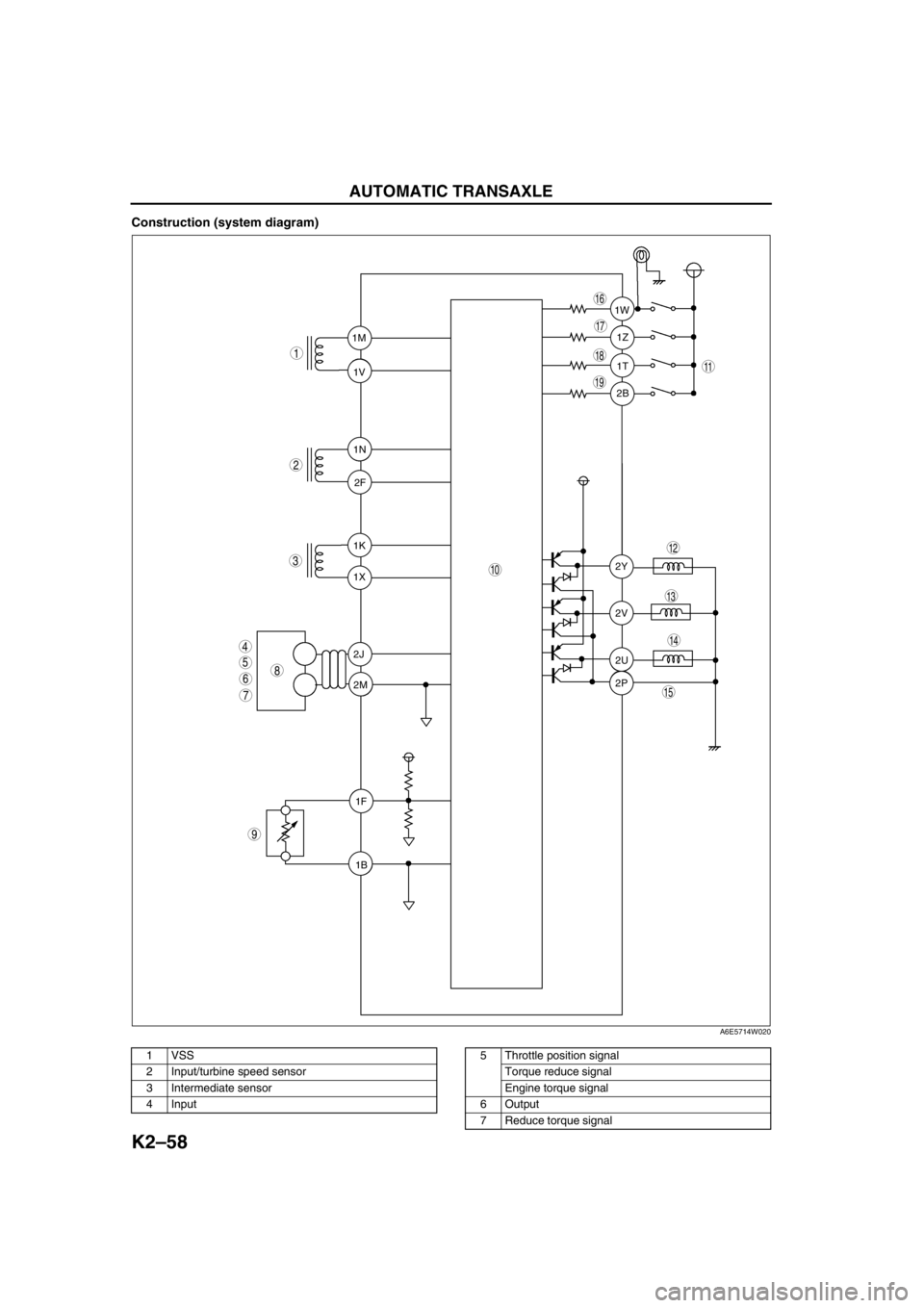
K2–58
AUTOMATIC TRANSAXLE
Construction (system diagram)
.
1T 1Z 1W
2B
2Y
2V
2U
2P 1K
1X 1M
1V
1N
2F
2J
2M
1F
1B
9
8
7
5
4
3
1
2
10
19
18
17
15
16
14
13
11
12
6
A6E5714W020
1 VSS
2 Input/turbine speed sensor
3 Intermediate sensor
4 Input5 Throttle position signal
Torque reduce signal
Engine torque signal
6Output
7 Reduce torque signal
Page 474 of 909
AUTOMATIC TRANSAXLE
K2–59
K2
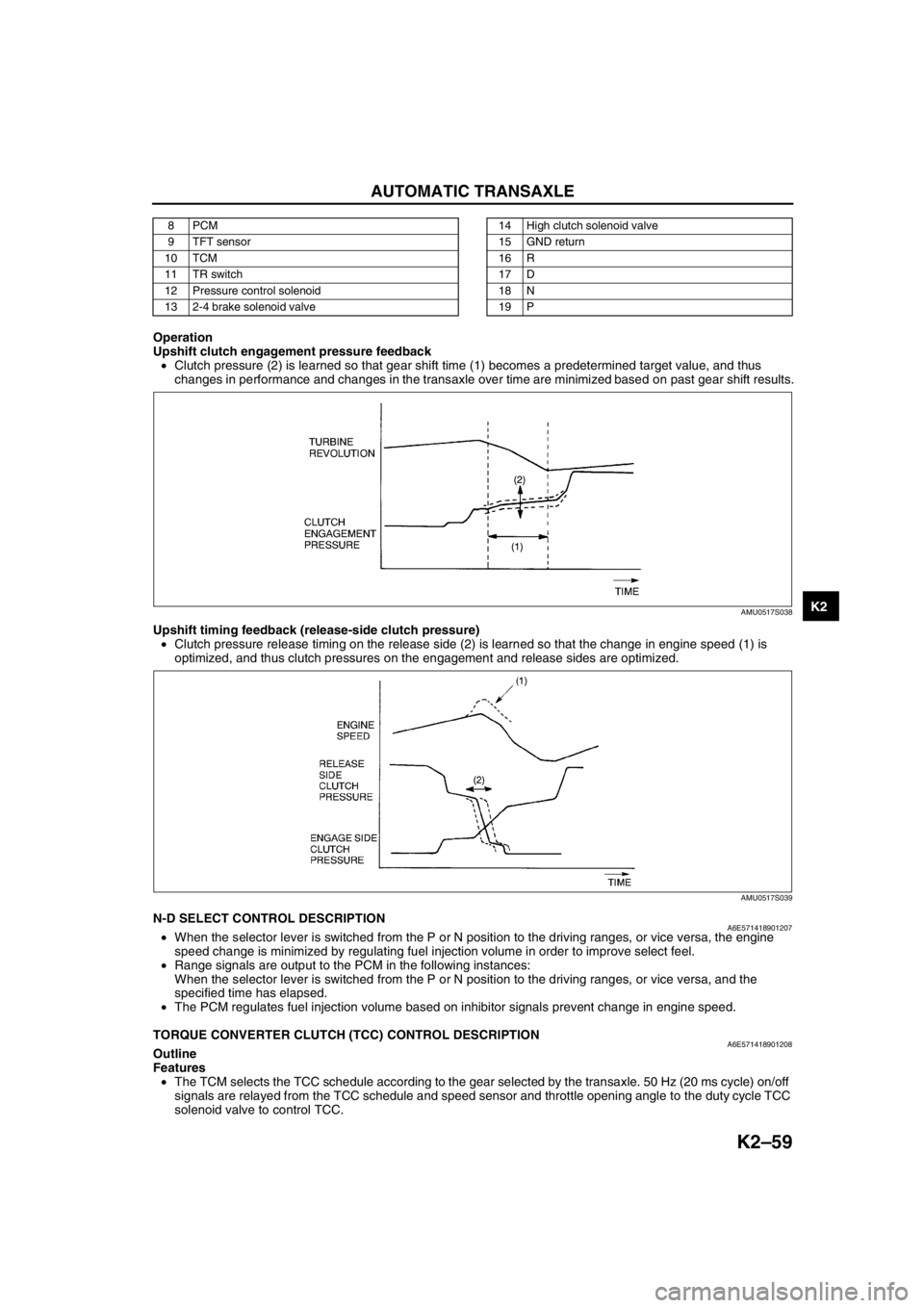
Operation
Upshift clutch engagement pressure feedback
•Clutch pressure (2) is learned so that gear shift time (1) becomes a predetermined target value, and thus
changes in performance and changes in the transaxle over time are minimized based on past gear shift results.
Upshift timing feedback (release-side clutch pressure)
•Clutch pressure release timing on the release side (2) is learned so that the change in engine speed (1) is
optimized, and thus clutch pressures on the engagement and release sides are optimized.
End Of SieN-D SELECT CONTROL DESCRIPTIONA6E571418901207•When the selector lever is switched from the P or N position to the driving ranges, or vice versa, the engine
speed change is minimized by regulating fuel injection volume in order to improve select feel.
•Range signals are output to the PCM in the following instances:
When the selector lever is switched from the P or N position to the driving ranges, or vice versa, and the
specified time has elapsed.
•The PCM regulates fuel injection volume based on inhibitor signals prevent change in engine speed.
End Of Sie
TORQUE CONVERTER CLUTCH (TCC) CONTROL DESCRIPTIONA6E571418901208Outline
Features
•The TCM selects the TCC schedule according to the gear selected by the transaxle. 50 Hz (20 ms cycle) on/off
signals are relayed from the TCC schedule and speed sensor and throttle opening angle to the duty cycle TCC
solenoid valve to control TCC.
8PCM
9 TFT sensor
10 TCM
11 TR switch
12 Pressure control solenoid
13 2-4 brake solenoid valve14 High clutch solenoid valve
15 GND return
16 R
17 D
18 N
19 P
AMU0517S038
AMU0517S039
Page 475 of 909
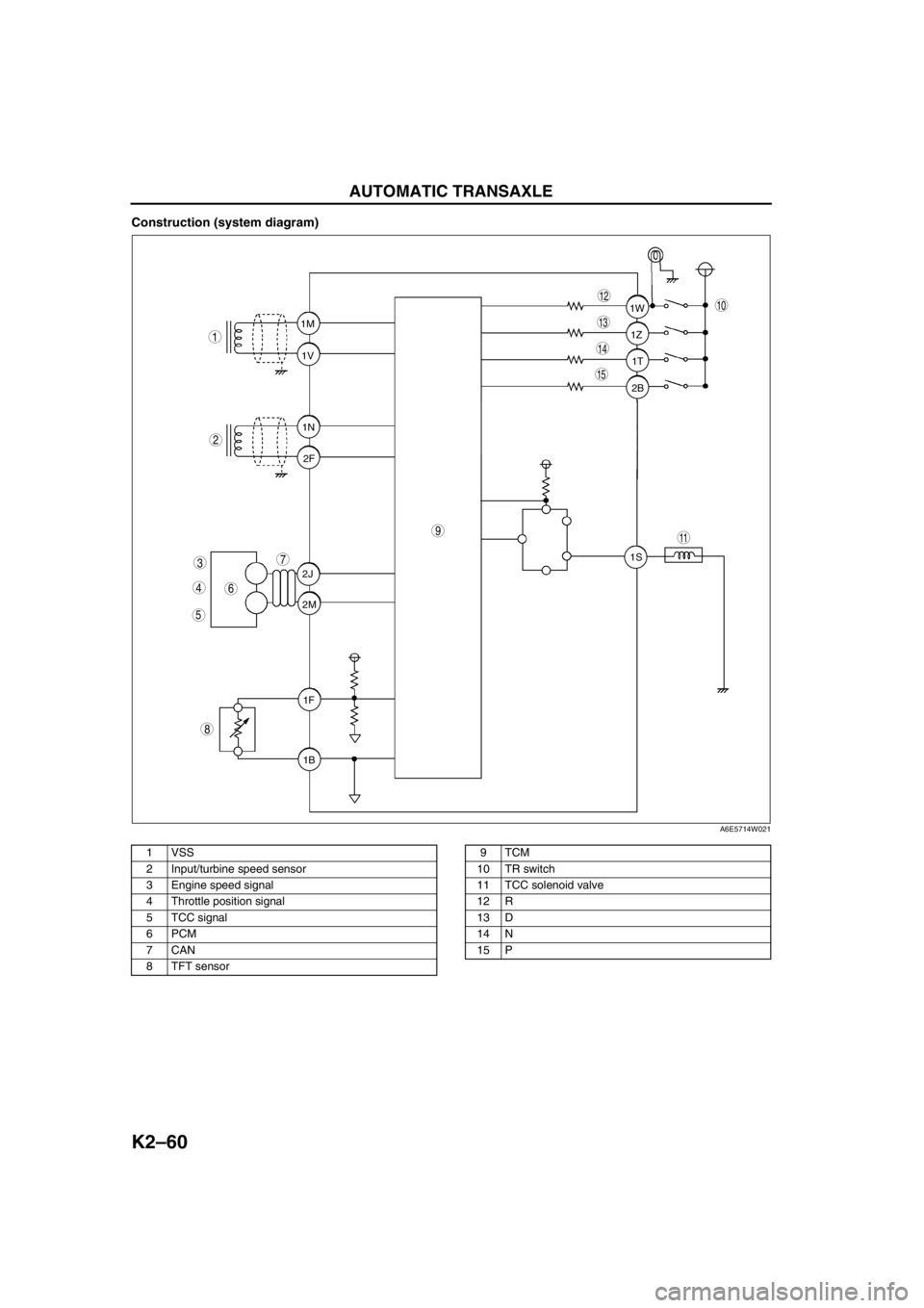
K2–60
AUTOMATIC TRANSAXLE
Construction (system diagram)
.
1T 1Z 1W
2B
1S 1M
1V
1N
2F
2J
2M
1F
1B
9
8
7
5
4
3
1
2
10
15
14
13
11
12
6
A6E5714W021
1 VSS
2 Input/turbine speed sensor
3 Engine speed signal
4 Throttle position signal
5 TCC signal
6PCM
7CAN
8 TFT sensor9TCM
10 TR switch
11 TCC solenoid valve
12 R
13 D
14 N
15 P