brake MAZDA 6 2002 Suplement User Guide
[x] Cancel search | Manufacturer: MAZDA, Model Year: 2002, Model line: 6, Model: MAZDA 6 2002Pages: 909, PDF Size: 17.16 MB
Page 18 of 909

GI–14
SC HE DU LE D MAI NTE NA NCE
Mai nten ance I temM ain tenan ce I nter val (Nu mber o f mo nths or km (mil es), whi chever co mes fi rst)
Mo nth s 12 24 36 48 60 72 84 96 108 120 132 144
×1000 km 15 30 45 60 75 90 105 120 135 150 165 180
×1000 mil es 9 18 27 36 45 54 63 72 81 90 99 108
EN GIN E
Engine valve clearanc e Audible inspec t every 120, 000 k m (75, 000 m iles), if nois y, adjus t
Drive belts *2III II II II II I
Engine oil *1RRR RR RR RR RR R
Engine oil filter *1RRR RR RR RR RR R
C OOLI NG SYSTEM
C ooling s ys tem
(I ncluding coolant level adjust ment )IIIIII
Engine coolantReplac e at f irst 4 years or 90,000 km (54,000 miles );
af ter that , ev ery 2 y ears
F UEL SYST EM
Air cleaner element *4 C C C R C C C R C C C R
F uel f ilter R eplace ev ery 105,000 km (63, 000 m iles)
F uel lines and hosesIIIIII
I GNI TI ON SYSTEM
Spark plugs Replac e every 90, 000 k m (54,000 miles )
EM ISSI ON CON TROL SYST EM
Ev aporat ive sy st em I I I
EL ECT RI CA L SYSTEM
Bat ter y elec troly te level and spec ific grav ity I I I I I I I I I I I I
All electrical system *5III II II II II I
C HA S S IS AN D BO DY
Brake lines, hos es and c onnect ions I I I I I I I I I I I I
Brake fluid *3IRI RI RI RI RI R
Parking brake III II II II II I
Power brak e unit and hoses I I I I I I I I I I I I
Disc brakes III II II II II I
Power st eering f luid, lines, hoses , and
c onnect ionsIII II II II II I
St eering operat ion and linkagesIIIIII
M anual t ransax le oil R R
Automatic transaxle fluid level IIIIII
Front and rear s uspens ion and ball joint s I I I I I
D rives haft dus t boots I I I I I
Ex haust s ys tem and heat shields Ins pect every 75, 000 k m (45,000 miles )
Body c ondition (for r ust , corros ion and
perforat ion)Ins pect annually
C abin air filt er (if ins talled) R R R R R R R R R R R R
Tyres (inc luding s pare t yre)
(w ith inflat ion pres sure adjust ment )III II II II II I
Page 19 of 909

SCHEDULED MAINTENANCE
GI–15
GI
For GCC
Applied VIN (assumed):
JM7 GG323✻✻
✻✻✻✻ ✻✻
# 128767-, JM7 GG423✻✻
✻✻✻✻ ✻✻
# 128767-, JM7 GG343✻✻
✻✻✻✻ ✻✻
# 128767-
JM7 GG443✻✻
✻✻✻✻ ✻✻
# 128767-, JM7 GG32F✻✻
✻✻✻✻ ✻✻
# 128767-, JM7 GG42F✻✻
✻✻✻✻ ✻✻
# 128767-
JM7 GG34F✻
✻✻ ✻✻
✻✻ ✻
# 128767-, JM7 GG44F✻
✻✻ ✻✻
✻✻ ✻
# 128767-, JM7 GY49F✻✻
✻✻✻✻ ✻✻
# 101432-
JM7 GY39F✻✻
✻✻✻✻ ✻✻
# 101432-, JM7 GY49F✻
✻✻ ✻
0# 101432-, JM7 GY39F✻
✻✻ ✻
0# 101432-
Chart symbols:
I : Inspect and clean, repair, adjust, or replace if necessary.
R : Replace
T:Tighten
C : Clean
Remarks:
•The ignition and fuel systems are highly important to the emission control system and to efficient engine operation. All
inspections and adjustments must be made by an Authorized Mazda Dealer.
•After the prescribed period, continue to follow the described maintenance at the recommended intervals.
•Refer below for a description of items marked* in the maintenance chart.
*1: If the vehicle is operated under any of the following conditions, change the engine oil and oil filter more often than
recommended intervals.
a. Driving in dusty conditions.
b. Extended periods of idling or low speed operation.
c. Driving for long period in cold temperatures or driving regularly at short distance only.
*2: Also inspect and adjust the power steering and air conditioner drive belts, if installed.
*3: If the brakes are used extensively (for example, continuous hard driving or mountain driving) or if the vehicle is
operated in extremely humid climates, change the brake fluid annually.
*4: If the vehicle is operated in very dusty or sandy areas, clean and if necessary, replace the air cleaner element more
often than the recommended intervals.
*5: This is a full function check of electrical systems such as lights, wiper and washer systems (including wiper blades),
and power windows.
*6: If the vehicle is operated under any of the following conditions, change the rear differential oil
every 45,000 km (27,000 miles).
a. Towing a trailer or using a car - top carrier
b. Driving in dusty, sandy or wet condition
c. Extended periods of idling or low speed operation
d. Repeated short trips of less than 16 km (10 miles)
*7: If this component has been submerged in water, the oil should be changed.
Maintenance ItemMaintenance Interval (Number of months or km (miles), whichever comes first)
Months 6 121824303642485460667278849096
×1000 km
10 20 30 40 50 60 70 80 90 100 110 120 130 140 150 160
×1000 miles6.25 12.5 18.75 25 31.25 37.5 43.75 50 56.25 62.5 68.75 75 81.25 87.5 93.75 100
ENGINE
Engine valve clearance Unleaded fuel Audible inspect every 120,000 km (75,000 miles), if noisy, adjust
leaded fuel I I I I
Drive belts *2IIIIIIIIIIIIIIII
Engine oil *1RRRRRRRRRRRRRRRR
Engine oil filter *1RRRRRRRRRRRRRRRR
COOLING SYSTEM
Cooling system IIIIIIII
Engine coolant Replace every 2 years
FUEL SYSTEM
Air cleaner element *4CCRCCRCC
Fuel filter R R R R
Fuel lines and hoses IIIIIIII
IGNITION SYSTEM
Spark plugs Unleaded fuel Replace every 100,000 km (62,500 miles)
Leaded fuel IIIIIIII
EMISSION CONTROL SYSTEM
Idle mixture (leaded fuel) IIIIIIII
Page 20 of 909

GI–16
SCHEDULED MAINTENANCE
Evaporative system (if installed) IIIIIIII
ELECTRICAL SYSTEM
Battery electrolyte level and specific gravity IIIIIIII
All electrical system *5IIIIIIII
CHASSIS AND BODY
Brake lines, hoses and connections IIIIIIII
Brake fluid *3IIIRIIIRIIIRIIIR
Parking brake IIIIIIIIIIIIIIII
Power brake unit and hoses IIIIIIII
Disc brakes IIIIIIIIIIIIIIII
Power steering fluid, lines, hoses, and connections I I I I I I I I I I I I I I I I
Steering operation and linkages IIIIIIII
Manual transaxle oilR
Automatic transaxle fluid level IIIIIIII
Rear differential oil (for 4WD)
*6*7
Transfer oil (for 4WD)
*7
Front and rear suspension and ball joints I I I I
Driveshaft dust boots I I I I
Bolts and nuts on chassis and body TTTTTTTT
Exhaust system and heat shields Inspect every 80,000 km (50,000 miles)
Cabin air filter (if installed) RRRRRRRR
Body condition
(for rust, corrosion and perforation)Inspect annually
Tyres (including spare tyre)
(with inflation pressure adjustment)IIIIIIII Maintenance ItemMaintenance Interval (Number of months or km (miles), whichever comes first)
Months 6 121824303642485460667278849096
×1000 km
10 20 30 40 50 60 70 80 90 100 110 120 130 140 150 160
×1000 miles6.25 12.5 18.75 25 31.25 37.5 43.75 50 56.25 62.5 68.75 75 81.25 87.5 93.75 100
Page 21 of 909

SCHEDULED MAINTENANCE
GI–17
GI
Scheduled Maintenance Service (Specific Work Required)
•The specific work required for each maintenance item is listed in the following table. (Please refer to the section
applicable to the model serviced.)
For Europe (L.H.D. U.K.)
Bold frames: New item
Maintenance Item Specific Work Required
ENGINE
Engine valve clearance Measure clearance
Drive beltsInspect for wear, cracks and fraying, and check tension.
Replace drive belt.
Engine timing belt Replace engine timing belt.
Engine oil Replace engine oil and inspect for leakage.
Oil filter Replace oil filter and inspect for leakage.
COOLING SYSTEM
Cooling system
(including coolant level adjustment)Check coolant level and quality, and inspect for leakage.
Engine coolant Replace coolant.
FUEL SYSTEM
Air cleaner elementInspect for dirt, oil and damage.
Clean air cleaner element (by blowing air).
Replace air cleaner element.
Fuel filter Replace fuel filter.
Fuel lines and hoses Inspect for cracks, leakage and loose connection.
Fuel injection system (for MZR-CD (RF Turbo)) Update to injection amount correction with WDS. (see W/M)
IGNITION SYSTEM (FOR GASOLINE)
Spark plugsInspect for wear, damage, carbon, high-tension lead condition and measure
plug gap.
Replace spark plugs.
EMISSION CONTROL SYSTEM
Evaporative system (for gasoline)Check system operation (see W/M), vapor lines, vacuum fitting hoses and
connection.
E.G.R. system (MZR-CR (RF Turbo))Check system operation (see W/M), vacuum fitting hoses and connection.
Update to MAF correction for E.G.R control with WDS. (see W/M)
ELECTRICAL SYSTEM
Battery electrolyte level and specific gravity Check level and specific gravity.
CHASSIS AND BODY
Brake fluidCheck fluid level and inspect for leakage.
Replace brake fluid.
Brake lines, hoses and connectionsInspect for cracks, damage, chafing, corrosion, scars, swelling and fluid
leakage.
Parking brake Check lever stroke.
Power brake unit and hosesCheck vacuum lines, connections and check valve for improper attachment,
air tightness, cracks chafing and deterioration.
Disc brakesTest for judder and noise. Inspect caliper for correct operation and fluid
leakage, brake pads for wear. Check disc plate condition and thickness.
Power steering fluid and linesCheck fluid level and lines for improper attachment, leakage, cracks,
damage, loose connections, chafing and deterioration.
Power steering fluid Check fluid level.
Power steering system and hosesCheck lines for improper attachment, leakage, cracks, damage, loose
connections, chafing and deterioration.
Steering operation and gear housingCheck that the steering wheel has the specified play. Be sure to check for
changes, such as excessive play, hard steering or strange noises.
Check gear housing and boots for looseness, damage and grease/gear oil
leakage.
Steering linkages tie rod ends and armsCheck ball joint, dust cover and other components for looseness, wear,
damage and grease leakage.
Front and rear suspension and ball joints Inspect for grease leakage, cracks, damage and looseness.
Manual transmission/transaxle oilCheck oil level and inspect for leakage.
Replace manual transmission/transaxle oil.
Automatic transmission/transaxle fluid level Check fluid level.
Page 94 of 909

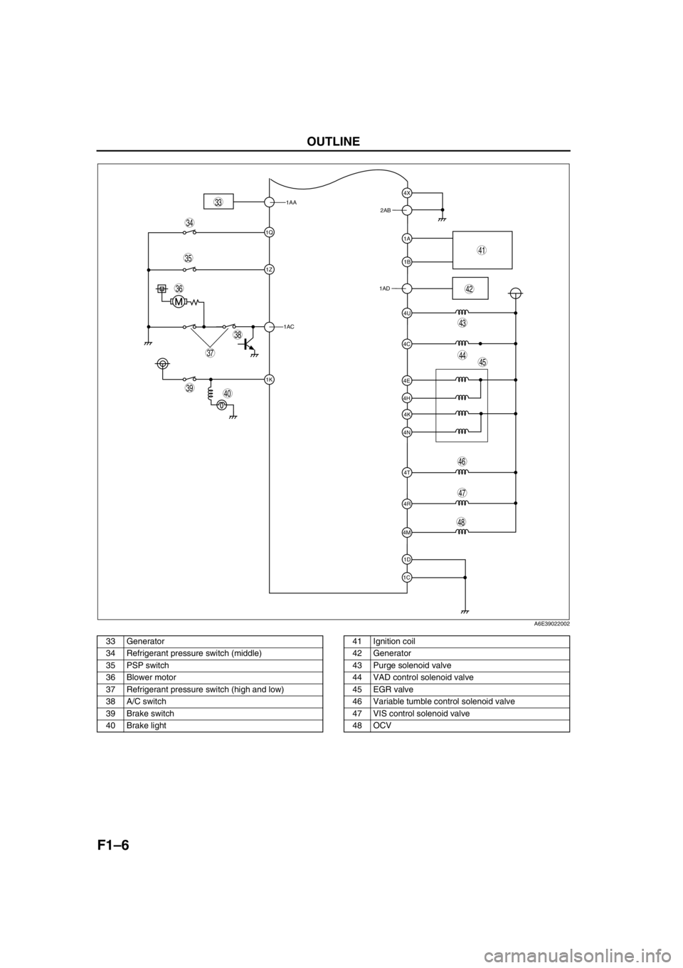
F1–6
OUTLINE
.
1AA
1Q
1Z
1AC
1K
1C1D 4M4R 4N4K 4H4E
4T 4C4U 1AD1B 1A 2AB4X
39
38
37
35
36
33
40
45
46
44
43
41
42
34
48
47
A6E39022002
33 Generator
34 Refrigerant pressure switch (middle)
35 PSP switch
36 Blower motor
37 Refrigerant pressure switch (high and low)
38 A/C switch
39 Brake switch
40 Brake light41 Ignition coil
42 Generator
43 Purge solenoid valve
44 VAD control solenoid valve
45 EGR valve
46 Variable tumble control solenoid valve
47 VIS control solenoid valve
48 OCV
Page 96 of 909

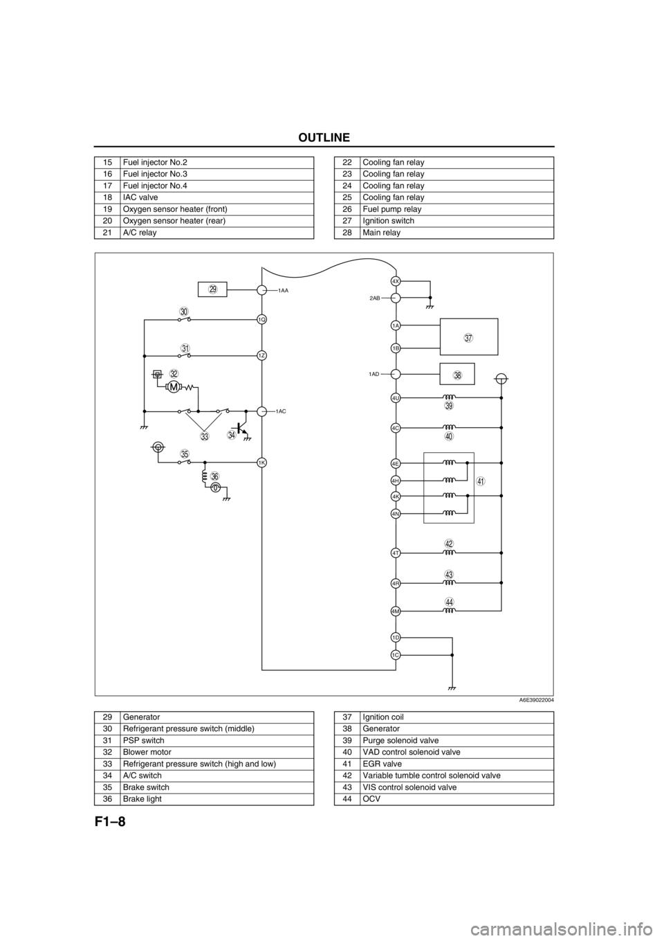
F1–8
OUTLINE
.
15 Fuel injector No.2
16 Fuel injector No.3
17 Fuel injector No.4
18 IAC valve
19 Oxygen sensor heater (front)
20 Oxygen sensor heater (rear)
21 A/C relay22 Cooling fan relay
23 Cooling fan relay
24 Cooling fan relay
25 Cooling fan relay
26 Fuel pump relay
27 Ignition switch
28 Main relay
1AA
1Q
1Z
1AC
1K
1C1D 4M4R 4N4K 4H4E
4T 4C4U 1AD1B 1A 2AB4X
39
38
37
35
36
33
31
32
40
44
43
41
42
34
29
30
A6E39022004
29 Generator
30 Refrigerant pressure switch (middle)
31 PSP switch
32 Blower motor
33 Refrigerant pressure switch (high and low)
34 A/C switch
35 Brake switch
36 Brake light37 Ignition coil
38 Generator
39 Purge solenoid valve
40 VAD control solenoid valve
41 EGR valve
42 Variable tumble control solenoid valve
43 VIS control solenoid valve
44 OCV
Page 102 of 909

F1–14
CONTROL SYSTEM
OUTLINEA6E394018880201•The control system is essentially carried over from the current Mazda6 (GG), except for the following. (See
Mazda6 Training Manual 3359-1*-02C.)
Vehicle Adoption
4WD ATX model
•TCM has been adopted. Due to this the PCM terminal of ATX device has been replaced to TCM. The ATX
device information which is needed by the fuel and emission control systems is communicated to the PCM by
the controller area network (CAN).
Unleaded (RON 90 or above) model
•BARO sensor has been eliminated. Due to this the BARO factor for purge control has been eliminated.
Input Device
×:Applicable
—: Not applicable
*
1: For MTX model
*2: With Immobilizer system
CONTROL SYSTEM
Item SignalMazda6 (GG, GY)
Remark for new model
4WD ATX Unleaded
(RON 90 or
above)Current
model
MAF/IAT sensor MAF and IAT×Same as current model
TP sensor TP×Same as current model
MAP sensor MAP×Same as current model
ECT sensor ECT×Same as current model
CMP sensorCylinder
identification×Same as current model
CKP sensor Engine revolution×Same as current model
Knock sensor Knocking×Same as current model
HO2S (Front, Rear)Oxygen
concentration×Same as current model
BARO sensor BARO×—×Same as current model
Neutral switch*
1Load/no load
distinction×Same as current model
Clutch switch*
1Load/no load
distinction×Same as current model
Brake switchBrake pedal
condition×Same as current model
PSP switchP/S oil pump load
condition×Same as current model
VSS Vehicle speed—×—
A/C switch, refrigerant
pressure switch (high,
low pressure)A/C operational×Same as current model
Refrigerant pressure
switch (middle
pressure)A/C compressor load×—×Same as current model
Battery Battery voltage×Same as current model
Generation voltage
(Generator terminal P)Generation voltage×Same as current model
Immobilizer unit*
2Immobilizer system
communication×—×Same as current model
Page 104 of 909

F1–16
CONTROL SYSTEM
STRUCTURAL VIEW (4WD)A6E394018880202
.
End Of Sie
9
8
7
5
4
3
10
1817
15
16
14
13
11
12
20
25
24
23
21
22
6
1
2
19
A6E39402000
1 MAF/IAT sensor
2 TP sensor
3 MAP sensor
4 CMP sensor
5 CKP sensor
6 ECT sensor
7 Knock sensor
8 HO2S (front)
9 HO2S (rear)
10 PSP switch
11 Brake switch
12 VAD control solenoid valve
13 IAC valve14 VIC solenoid valve
15 Variable tumble control solenoid valve
16 OCV
17 Fuel injector
18 Ignition coil
19 Purge solenoid valve
20 EGR valve
21 BARO sensor
22 PCM (R.H.D.)
23 TCM (R.H.D)
24 PCM (L.H.D.)
25 TCM (L.H.D)
Page 106 of 909

F1–18
CONTROL SYSTEM
*1: For MTX model
*2: For 2WD ATX model
*3: For L3 engine
End Of Sie
1 MAF/IAT sensor
2 TP sensor
3 MAP sensor
4 CMP sensor
5 CKP sensor
6 ECT sensor
7 Knock sensor
8 HO2S (front, rear)
9 PSP switch
10 Vehicle speedometer sensor
11
Clutch switch*
1
12
Neutral switch*1
13
TR switch*2
14 Brake switch
15 A/C switch
16 Refrigerant pressure switch
17 Generator (terminal P: generation voltage)
18 Battery
19
VAD control solenoid valve*
3
20 IAC valve
21
VIC solenoid valve*
3
22 Variable tumble control solenoid valve
23
OCV*
3
24 Fuel injector
25 Fuel pump relay
26 Ignition coil
27 Purge solenoid valve
28 EGR valve
29 Oxygen sensor heater (front, rear)
30 A/C relay
31 Cooling fan relay
32 Generator (terminal D: field coil)
33
VAD control*
3
34 IAC
35
VIC*
3
36 VTCS
37
Variable valve timing control*
3
38 Fuel injection control
39 Fuel pump control
40 Electronic spark advance (ESA) control
41 Purge control
42 EGR control
43 Oxygen sensor heater control
44 A/C cut-off control
45 Electrical fan control
46 Generator control
Page 107 of 909

CONTROL SYSTEM
F1–19
F1
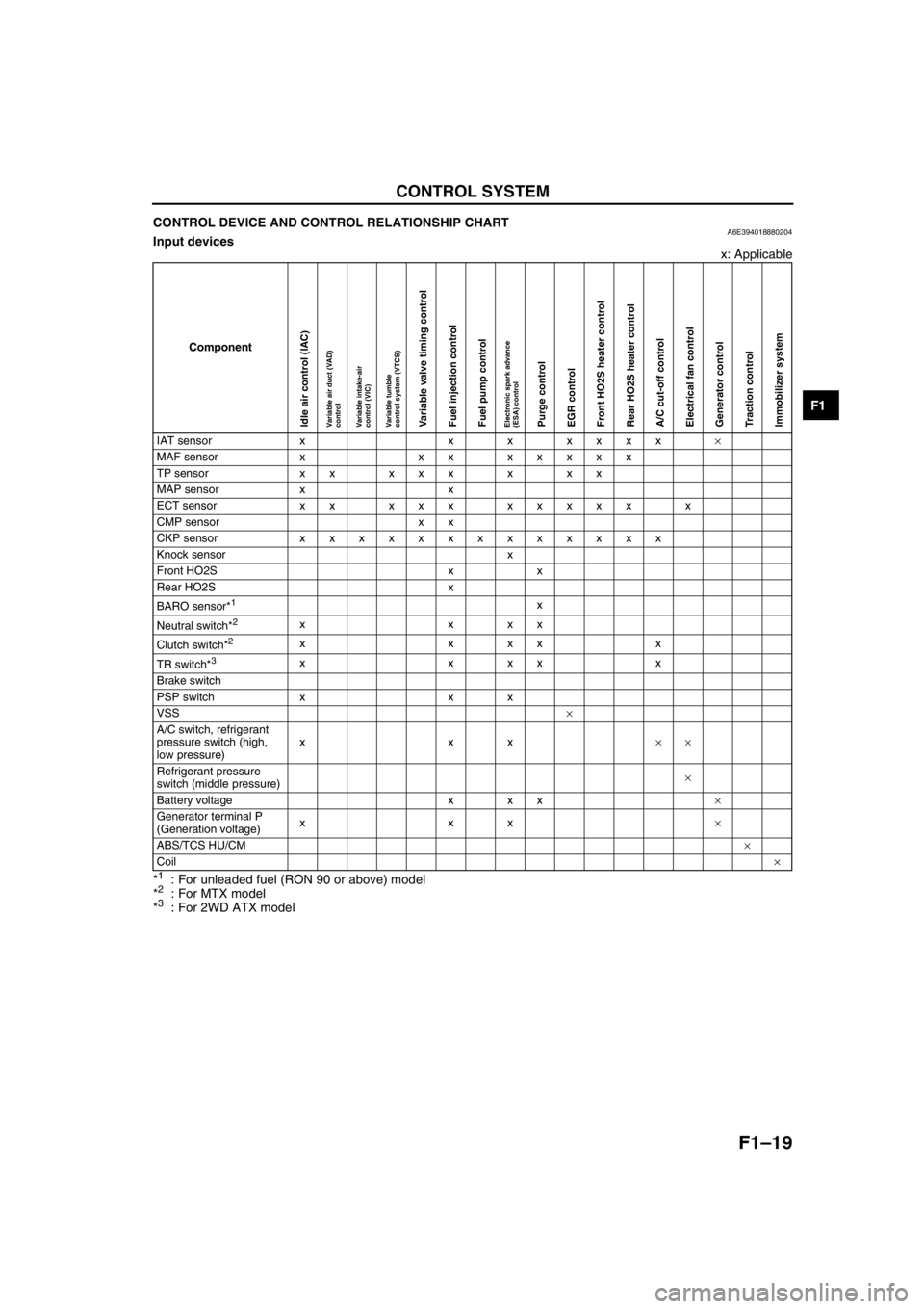
CONTROL DEVICE AND CONTROL RELATIONSHIP CHARTA6E394018880204Input devices
x: Applicable
*
1: For unleaded fuel (RON 90 or above) model
*2: For MTX model
*3: For 2WD ATX model
Component
IAT sensor x x x xxxx×
MAF sensor x xx xxxxx
TP sensor x x x x x x x x
MAP sensor x x
ECT sensor xx xxx xxxxx x
CMP sensor x x
CKP sensor xxxxxxxxxxxxx
Knock sensor x
Front HO2S x x
Rear HO2S x
BARO sensor*
1x
Neutral switch*
2xxxx
Clutch switch*
2xxxxx
TR switch*
3xxxxx
Brake switch
PSP switch x x x
VSS×
A/C switch, refrigerant
pressure switch (high,
low pressure)xxx××
Refrigerant pressure
switch (middle pressure)×
Battery voltage x x x×
Generator terminal P
(Generation voltage)xxx×
ABS/TCS HU/CM×
Coil×
Idle air control (IAC)Variable air duct (VAD)
controlVariable intake-air
control (VIC)Variable tumble
control system (VTCS)Variable valve timing controlFuel injection controlFuel pump controlElectronic spark advance
(ESA) controlPurge controlEGR controlFront HO2S heater controlRear HO2S heater controlA/C cut-off controlElectrical fan controlGenerator controlTraction controlImmobilizer system