charging MAZDA 6 2002 Suplement User Guide
[x] Cancel search | Manufacturer: MAZDA, Model Year: 2002, Model line: 6, Model: MAZDA 6 2002Pages: 909, PDF Size: 17.16 MB
Page 345 of 909
TROUBLESHOOTING
F2–193
F2
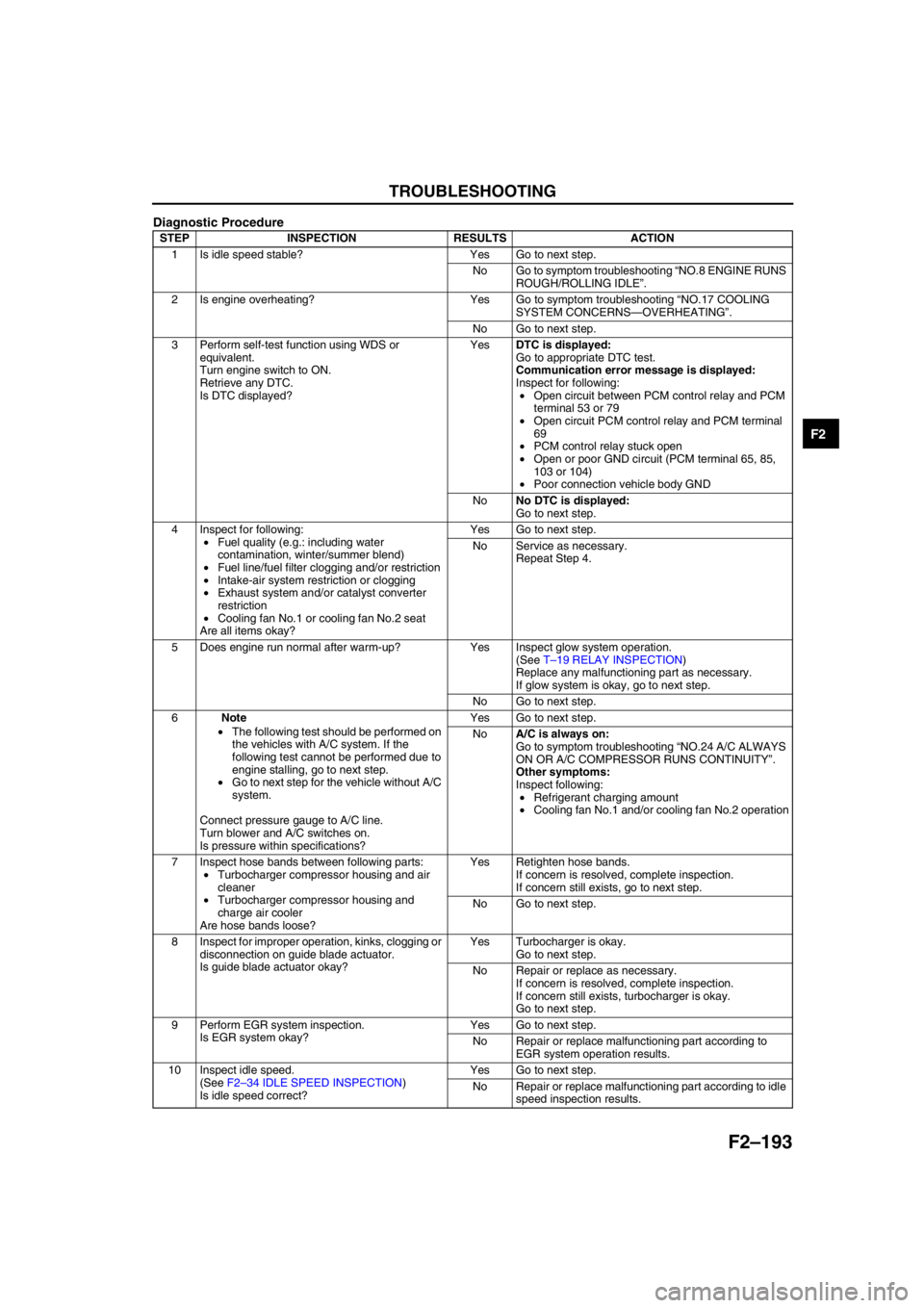
Diagnostic Procedure
STEP INSPECTION RESULTS ACTION
1 Is idle speed stable? Yes Go to next step.
No Go to symptom troubleshooting “NO.8 ENGINE RUNS
ROUGH/ROLLING IDLE”.
2 Is engine overheating? Yes Go to symptom troubleshooting “NO.17 COOLING
SYSTEM CONCERNS—OVERHEATING”.
No Go to next step.
3 Perform self-test function using WDS or
equivalent.
Turn engine switch to ON.
Retrieve any DTC.
Is DTC displayed?YesDTC is displayed:
Go to appropriate DTC test.
Communication error message is displayed:
Inspect for following:
•Open circuit between PCM control relay and PCM
terminal 53 or 79
•Open circuit PCM control relay and PCM terminal
69
•PCM control relay stuck open
•Open or poor GND circuit (PCM terminal 65, 85,
103 or 104)
•Poor connection vehicle body GND
NoNo DTC is displayed:
Go to next step.
4 Inspect for following:
•Fuel quality (e.g.: including water
contamination, winter/summer blend)
•Fuel line/fuel filter clogging and/or restriction
•Intake-air system restriction or clogging
•Exhaust system and/or catalyst converter
restriction
•Cooling fan No.1 or cooling fan No.2 seat
Are all items okay?Yes Go to next step.
No Service as necessary.
Repeat Step 4.
5 Does engine run normal after warm-up? Yes Inspect glow system operation.
(See T–19 RELAY INSPECTION)
Replace any malfunctioning part as necessary.
If glow system is okay, go to next step.
No Go to next step.
6Note
•The following test should be performed on
the vehicles with A/C system. If the
following test cannot be performed due to
engine stalling, go to next step.
•Go to next step for the vehicle without A/C
system.
Connect pressure gauge to A/C line.
Turn blower and A/C switches on.
Is pressure within specifications?Yes Go to next step.
NoA/C is always on:
Go to symptom troubleshooting “NO.24 A/C ALWAYS
ON OR A/C COMPRESSOR RUNS CONTINUITY”.
Other symptoms:
Inspect following:
•Refrigerant charging amount
•Cooling fan No.1 and/or cooling fan No.2 operation
7 Inspect hose bands between following parts:
•Turbocharger compressor housing and air
cleaner
•Turbocharger compressor housing and
charge air cooler
Are hose bands loose?Yes Retighten hose bands.
If concern is resolved, complete inspection.
If concern still exists, go to next step.
No Go to next step.
8 Inspect for improper operation, kinks, clogging or
disconnection on guide blade actuator.
Is guide blade actuator okay?Yes Turbocharger is okay.
Go to next step.
No Repair or replace as necessary.
If concern is resolved, complete inspection.
If concern still exists, turbocharger is okay.
Go to next step.
9 Perform EGR system inspection.
Is EGR system okay?Yes Go to next step.
No Repair or replace malfunctioning part according to
EGR system operation results.
10 Inspect idle speed.
(See F2–34 IDLE SPEED INSPECTION)
Is idle speed correct?Yes Go to next step.
No Repair or replace malfunctioning part according to idle
speed inspection results.
Page 355 of 909

TROUBLESHOOTING
F2–203
F2
3 Perform self-test function using WDS or
equivalent.
Turn engine switch to ON.
Retrieve any DTC.
Is DTC displayed?YesDTC is displayed:
Go to appropriate DTC test.
Communication error message is displayed:
Inspect for following:
•Open circuit between PCM control relay and PCM
terminal 53 or 79
•Open circuit PCM control relay and PCM terminal
69
•PCM control relay stuck open
•Open or poor GND circuit (PCM terminal 65, 85,
103 or 104)
•Poor connection vehicle body GND
NoNo DTC is displayed:
Go to next step.
4Note
•The following test should be performed on
the vehicles with A/C system. If the
following test cannot be performed due to
engine stalling, go to next step.
•Go to next step for the vehicle without A/C
system.
Connect pressure gauge to A/C line.
Turn blower and A/C switches on.
Is pressure within specifications?Yes Go to next step
NoA/C is always on:
Go to symptom troubleshooting “NO.24 A/C ALWAYS
ON OR A/C COMPRESSOR RUNS
CONTINUOUSLY”.
Other symptoms:
Inspect following:
•Refrigerant charging amount
•Cooling fan No.1 and/or cooling fan No.2
operation.
5 Access ECT PID.
Drive vehicle while monitoring PID.
Is PID within specification?Yes Go to next step.
No Inspect for coolant leakage, cooling fan No.1 and
cooling fan No.2 operations or thermostat operation.
6 Inspect idle speed.
(See F2–34 IDLE SPEED INSPECTION)
Is idle speed okay?Yes Go to next step.
No Go to symptom troubleshooting “NO.7 SLOW
RETURN TO IDLE”.
7 Perform EGR system inspection.
Is EGR system okay?Yes Go to next step.
No Repair or replace malfunctioning part according to
EGR system operation results.
8 Inspect adjustment of accelerator position
sensor and idle switch.
(See F2–72 ACCELERATOR POSITION
SENSOR INSPECTION)
(See F2–70 IDLE SWITCH INSPECTION)
Are accelerator position sensor and idle switch
adjusted correctly?Yes Go to next step.
No Adjust accelerator position sensor and idle switch
correctly.
(See F2–73 ACCELERATOR POSITION SENSOR
ADJUSTMENT)
(See F2–71 IDLE SWITCH ADJUSTMENT)
9 Is engine compression correct?
(See B2–8 COMPRESSION INSPECTION)Yes Go to next step.
No Inspect for following:
•Damaged valve seat
•Worn valve stem and valve guide
•Worn or stuck piston ring
•Worn piston, piston ring or cylinder
•Improper valve timing
Service as necessary.
10 Inspect fuel injector.
(See F2–56 FUEL INJECTOR INSPECTION)
Is fuel injector okay?Yes Go to next step.
No Repair or replace as necessary.
11 Perform turbocharger inspection.
(See F2–38 TURBOCHARGER INSPECTION)
Is turbocharger okay?Yes Go to next step.
No Replace turbocharger.
12 Inspect guide blade valve operation.
(See F2–229 ENGINE CONTROL SYSTEM
OPERATION INSPECTION)
Is there any problem?Yes Repair or replace as necessary.
No Go to next step.
13 Visually inspect CKP sensor and teeth of pulse
wheel.
Are CKP sensor and teeth of pulse wheel okay?Yes Go to next step.
No Replace malfunctioning parts. STEP INSPECTION RESULTS ACTION
Page 374 of 909

F2–222
TROUBLESHOOTING
NO.23 A/C DOES NOT WORK SUFFICIENTLYA6E408018881225
Diagnostic Procedure
End Of Sie
23 A/C DOES NOT WORK SUFFICIENTLY
DESCRIPTION•A/C compressor magnetic clutch does not engage when A/C switch is turned on.
POSSIBLE
CAUSE•Improper refrigerant charge amount
•Open A/C switch magnetic clutch
•Open circuit between A/C relay and A/C magnetic clutch
•Poor GND of A/C magnetic clutch
•Improper A/C magnetic clutch clearance
•Refrigerant pressure switch is stuck open
•A/C relay is stuck open
•Improper A/C cut-off control
•Open circuit between A/C switch and PCM through both refrigerant pressure switch and A/C amplifier
STEP INSPECTION RESULTS ACTION
1 Perform self-test function using WDS or
equivalent.
Turn engine switch to ON.
Retrieve any DTC.
Is DTC displayed?YesDTC is displayed:
Go to appropriate DTC test.
Communication error message is displayed:
Inspect for following:
•Open circuit between PCM control relay and PCM
terminal 53 or 79
•Open circuit PCM control relay and PCM terminal
69
•PCM control relay stuck open
•Open or poor GND circuit (PCM terminal 65, 85,
103 or 104)
•Poor connection vehicle body GND
YesNo DTC is displayed:
Go to appropriate DTC test.
2 Disconnect A/C compressor connector.
Start engine and turn A/C switch to ON.
Is there correct voltage at terminal of A/C
compressor magnetic clutch connector?
Specification
More than 10.5 VYes Inspect for GND condition of magnetic clutch on A/C
compressor.
If GND condition is okay, inspect magnetic clutch coil
for open circuit.
No Go to next step.
3 Disconnect refrigerant pressure switch
connector.
Connect jumper wire between terminals of
refrigerant pressure switch connector.
Turn engine switch to ON.
Turn A/C switch on and set blower fan at any
speed.
Measure PCM terminal 84 voltage.
Is voltage below 1.0 V?Yes Inspect refrigerant pressure switch operation.
If switch is okay, go to next step.
No Inspect for following:
•A/C switch is stuck open
•Open circuit between refrigerant pressure switch
and PCM terminal 84
•Open circuit of blower motor fan switch and
resistor (if blower motor does not operate)
•Evaporator temperature sensor and A/C amplifier
4 Inspect A/C cut-off operation.
Does A/C cut-off work properly?Yes Go to next step.
No Repair or replace malfunctioning part according to A/C
cut-off system inspection results.
5 Remove jumper wire from switch connector.
Reconnect connector to refrigerant pressure
switch.
Start engine and turn A/C switch on.
Does fan operate?Yes Inspect for stuck open A/C relay.
Replace if necessary.
No Inspect following and repair or replace as necessary:
•Refrigerant charging amount
•Seized A/C compressor
6 Verify test results.
•If okay, return to diagnostic index to service any additional symptoms.
•If malfunction remains, replace PCM. (See F2–64 PCM REMOVAL/INSTALLATION)
Page 377 of 909

TROUBLESHOOTING
F2–225
F2
NO.26 CONSTANT VOLTAGEA6E408018881228
Diagnostic Procedure
26 CONSTANT VOLTAGE
DESCRIPTION•Incorrect constant voltage.
POSSIBLE
CAUSE•Constant voltage circuit malfunction
•Accelerator positions sensor or related circuit malfunction
•Fuel pressure sensor or related circuit malfunction
•Boost sensor or related circuit malfunction
•ECT sensor GND circuit malfunction
•MAF/IAT sensor GND circuit malfunction
•IAT sensor No.2 GND circuit malfunction
•Fuel temperature sensor GND circuit malfunction
Note
•Accelerator position sensor, fuel pressure sensor and boost sensor use constant voltage.
STEP INSPECTION RESULTS ACTION
1 Disconnect appropriate sensor connectors
(accelerator position sensor, boost sensor and
fuel pressure sensor) where constant voltage
circuits inspection failed.
Turn engine switch to ON position.
Measure voltage between following appropriate
sensor connector terminals:
•Constant voltage terminal and GND terminal.
Is constant voltage above 6.0 V?Yes Repair constant voltage circuit short to power in
harness.
No Go to next step.
2 Is voltage across battery terminals above 10.5
V?Yes Go to next step.
No Inspect charging system.
3 Turn engine switch to OFF.
Leave appropriate sensor connectors
disconnected where constant voltage inspection
failed.
Measure voltage between positive terminal and
GND circuit at appropriate sensor vehicle
harness connector.
Is voltage above 10.5 V and within 1.0 V of
battery voltage?Yes Go to next step.
No Go to Step 8.
4Note
•Purpose of this step is to determine if
WDS or equivalent is communicating with
PCM.
Turn engine switch to ON.
Attempt to access ECT PID.
Can ECT PID be accessed?Yes Go to Step 7.
No Go to next step.
5 Turn engine switch to OFF.
Disconnect accelerator position sensor and
PCM connectors.
Turn engine switch to ON.
Measure voltage between PCM connector
terminals 104 and 53/79.
Is voltage greater than 10.5 V?Yes Go to next step.
No Repair open circuit between PCM terminal 53/79 and
PCM control relay.
6 Leave accelerator position sensor and PCM
connectors disconnected.
Measure resistance between PCM connector
terminals 104 and 90.
Is resistance greater than 10,000 ohms?Yes Inspect sensor connector for constant voltage again.
No Repair constant voltage circuit short to GND.
7 Turn engine switch to OFF.
Leave accelerator position sensor
disconnected.Disconnect PCM connector.
Measure resistance between PCM connector 90
and constant voltage circuit at appropriate
sensor connector.
Is resistance less than 5.0 ohms?Yes Inspect sensor connector for constant voltage again.
No Repair open constant voltage circuit.
Page 384 of 909
G–1
G
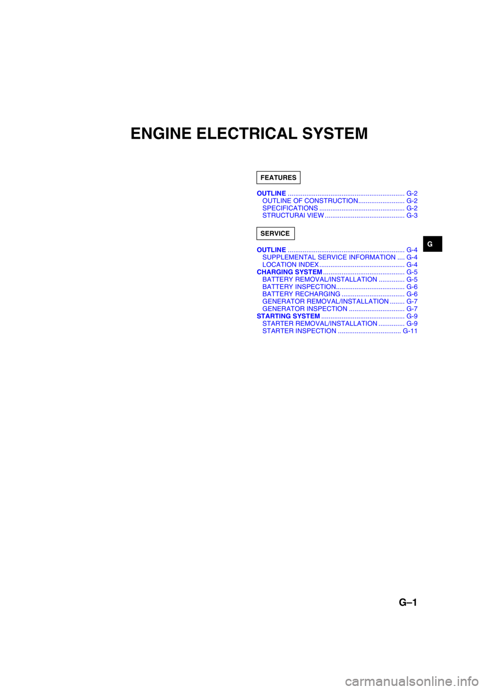
GENGINE ELECTRICAL SYSTEM
OUTLINE............................................................... G-2
OUTLINE OF CONSTRUCTION......................... G-2
SPECIFICATIONS .............................................. G-2
STRUCTURAl VIEW ........................................... G-3
OUTLINE............................................................... G-4
SUPPLEMENTAL SERVICE INFORMATION .... G-4
LOCATION INDEX .............................................. G-4
CHARGING SYSTEM............................................ G-5
BATTERY REMOVAL/INSTALLATION .............. G-5
BATTERY INSPECTION..................................... G-6
BATTERY RECHARGING .................................. G-6
GENERATOR REMOVAL/INSTALLATION ........ G-7
GENERATOR INSPECTION .............................. G-7
STARTING SYSTEM............................................. G-9
STARTER REMOVAL/INSTALLATION .............. G-9
STARTER INSPECTION .................................. G-11 FEATURES
SERVICE
Page 387 of 909
G–4
OUTLINE
SUPPLEMENTAL SERVICE INFORMATIONA6E470202000204•The following changes and/or additions have been made since publication of the Mazda6 Workshop Manual
(1730-1*-02C).
Battery
•Removal/Installation procedure has been added. (MZR-CD (RF Turbo) engine model)
•Inspection procedure has been added. (MZR-CD (RF Turbo) engine model)
•Recharging procedure has been added. (MZR-CD (RF Turbo) engine model)
Generator
•Removal/Installation procedure has been added. (MZR-CD (RF Turbo) engine model)
•Inspection procedure has been added. (MZR-CD (RF Turbo) engine model)
Starter
•Removal/Installation procedure has been added.
•Inspection procedure has been added. (MZR-CD (RF Turbo) engine model)
End Of Sie
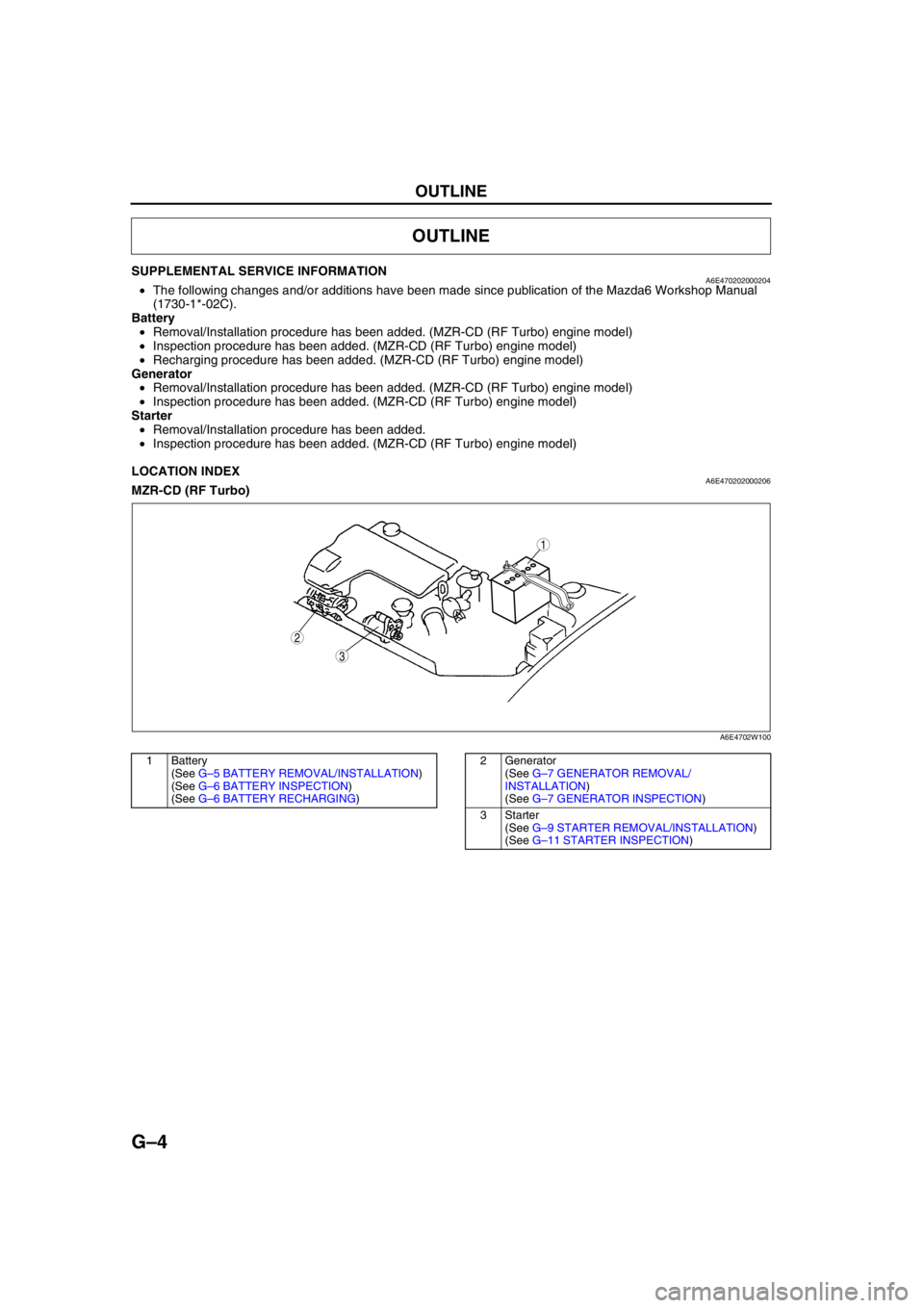
LOCATION INDEXA6E470202000206MZR-CD (RF Turbo)
.
End Of Sie
OUTLINE
3
1
2
A6E4702W100
1 Battery
(See G–5 BATTERY REMOVAL/INSTALLATION)
(See G–6 BATTERY INSPECTION)
(See G–6 BATTERY RECHARGING)2 Generator
(See G–7 GENERATOR REMOVAL/
INSTALLATION)
(See G–7 GENERATOR INSPECTION)
3Starter
(See G–9 STARTER REMOVAL/INSTALLATION)
(See G–11 STARTER INSPECTION)
Page 388 of 909

CHARGING SYSTEM
G–5
G
BATTERY REMOVAL/INSTALLATIONA6E471018520201MZR-CD (RF Turbo)
1. Remove in the order indicated in the table.
2. Install in the reverse order of removal.
End Of Sie
CHARGING SYSTEM
4.0—6.8 N·m
{40.8—69.3 kgf·cm, 35.5—60.1 in·lbf}
7.9—11.7 N·m
{80.6—119.3 kgf·cm, 70.0—103.5 in·lbf}
5
4
3
1
2
A6E4710W103
1 Negative battery cable
2 Positive battery cable
3 Battery clamp4 Battery
5 Battery tray
Page 389 of 909

G–6
CHARGING SYSTEM
BATTERY INSPECTIONA6E471018520202MZR-CD (RF Turbo)
Battery
1. Inspect the battery with the following procedure.
Load test chart
Battery positive voltage with load
Back-up Current
1. Verify that the engine switch is off and that the engine key has been removed.
2. Disconnect the negative battery cable.
Caution
•Operating electrical loads while measuring the back-up current can damage the circuit tester.
3. Measure the back-up current between the negative battery terminal and the negative battery cable.
(1) If the current exceeds the maximum, remove the fuses in the main fuse block and the fuse block one by
one while measuring the back-up current.
(2) Inspect and repair harnesses and connectors on the fuse where the current has been reduced.
Back-up current
20 mA max.
End Of Sie
BATTERY RECHARGINGA6E471018520203MZR-CD (RF Turbo)
Caution
•To avoid damage to the battery, do not quick charge for over 30 min.
•When disconnecting the battery, remove the negative cable first and install it last to prevent
damage to electrical components or the battery.
•To avoid deformation or damage to the battery, remove the battery plugs while charging the
battery.
Step Inspection Result Action
1Measure open circuit
voltage of battery.Above
12.4 VGo to Step
3.
Below
12.4 VGo to next
step.
2Quick-charge for 30 min.
and recheck voltage.Above
12.4 VGo to next
step.
Below
12.4 VReplace
battery.
3Apply load test (see load
test chart) to battery using a
battery load tester and
record battery voltage after
15 s. Is voltage more than
specification?YesBattery
okay.
NoReplace
battery.
Battery Load (A)
95D31L (64) 250
115D31L (70) 320
Approximate battery temp. Minimum voltage (V)
21°C {70°F} 9.6
15°C {60°F} 9.5
10°C {50°F} 9.4
4°C {40°F} 9.3
–1°C {30°F} 9.1
–7°C {20°F} 8.9
–12°C {10°F} 8.7
–18°C {0°F} 8.5
Page 390 of 909
CHARGING SYSTEM
G–7
G
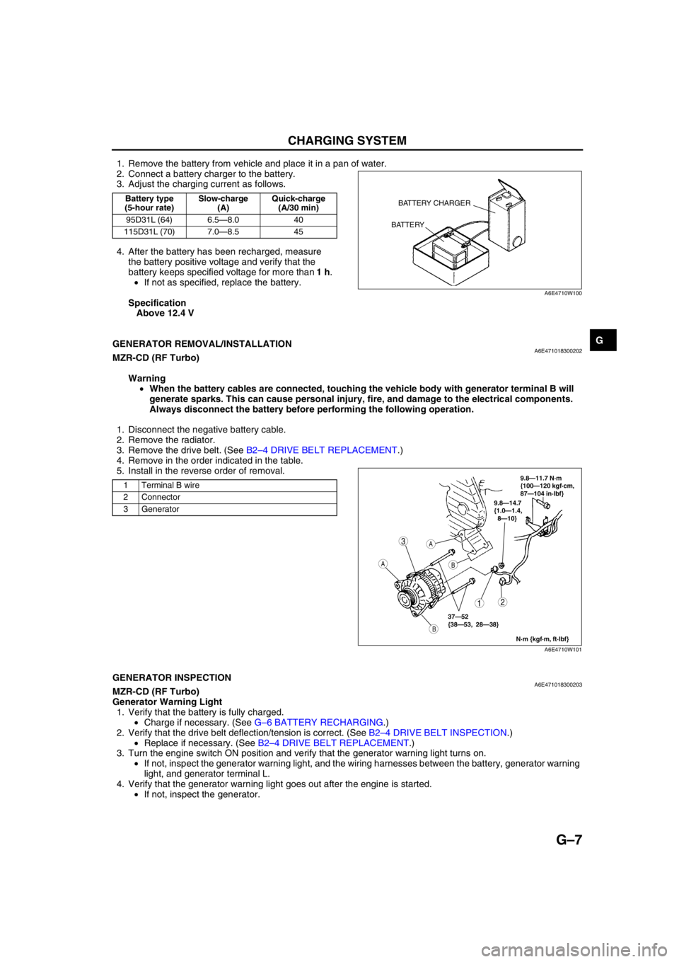
1. Remove the battery from vehicle and place it in a pan of water.
2. Connect a battery charger to the battery.
3. Adjust the charging current as follows.
4. After the battery has been recharged, measure
the battery positive voltage and verify that the
battery keeps specified voltage for more than 1 h.
•If not as specified, replace the battery.
Specification
Above 12.4 V
End Of Sie
GENERATOR REMOVAL/INSTALLATIONA6E471018300202MZR-CD (RF Turbo)
Warning
•When the battery cables are connected, touching the vehicle body with generator terminal B will
generate sparks. This can cause personal injury, fire, and damage to the electrical components.
Always disconnect the battery before performing the following operation.
1. Disconnect the negative battery cable.
2. Remove the radiator.
3. Remove the drive belt. (See B2–4 DRIVE BELT REPLACEMENT.)
4. Remove in the order indicated in the table.
5. Install in the reverse order of removal.
End Of SieGENERATOR INSPECTIONA6E471018300203MZR-CD (RF Turbo)
Generator Warning Light
1. Verify that the battery is fully charged.
•Charge if necessary. (See G–6 BATTERY RECHARGING.)
2. Verify that the drive belt deflection/tension is correct. (See B2–4 DRIVE BELT INSPECTION.)
•Replace if necessary. (See B2–4 DRIVE BELT REPLACEMENT.)
3. Turn the engine switch ON position and verify that the generator warning light turns on.
•If not, inspect the generator warning light, and the wiring harnesses between the battery, generator warning
light, and generator terminal L.
4. Verify that the generator warning light goes out after the engine is started.
•If not, inspect the generator.
Battery type
(5-hour rate)Slow-charge
(A)Quick-charge
(A/30 min)
95D31L (64) 6.5—8.0 40
115D31L (70) 7.0—8.5 45BATTERY CHARGER
BATTERY
A6E4710W100
1 Terminal B wire
2 Connector
3 Generator
3
12
A
B
A
B
9.8—14.7
{1.0—1.4,
8—10}
N·m {kgf·m, ft·lbf}
37—52
{38—53, 28—38}
9.8—11.7 N·m
{100—120 kgf·cm,
87—104 in·lbf}
A6E4710W101
Page 391 of 909
G–8
CHARGING SYSTEM
Generator
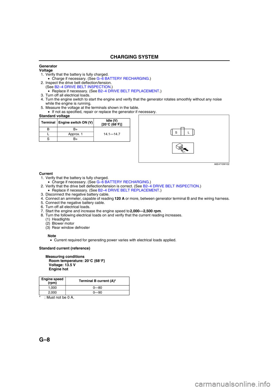
Voltage
1. Verify that the battery is fully charged.
•Charge if necessary. (See G–6 BATTERY RECHARGING.)
2. Inspect the drive belt deflection/tension.
(See B2–4 DRIVE BELT INSPECTION.)
•Replace if necessary. (See B2–4 DRIVE BELT REPLACEMENT.)
3. Turn off all electrical loads.
4. Turn the engine switch to start the engine and verify that the generator rotates smoothly without any noise
while the engine is running.
5. Measure the voltage at the terminals shown in the table.
•If not as specified, repair or replace the generator if necessary.
Standard voltage
Current
1. Verify that the battery is fully charged.
•Charge if necessary. (See G–6 BATTERY RECHARGING.)
2. Verify that the drive belt deflection/tension is correct. (See B2–4 DRIVE BELT INSPECTION.)
•Replace if necessary. (See B2–4 DRIVE BELT REPLACEMENT.)
3. Disconnect the negative battery cable.
4. Connect an ammeter, capable of reading 120 A or more, between generator terminal B and the wiring harness.
5. Connect the negative battery cable.
6. Turn off all electrical loads.
7. Start the engine and increase the engine speed to 2,000—2,500 rpm.
8. Turn the following electrical loads on and verify that the current reading increases.
(1) Headlights
(2) Blower motor
(3) Rear window defroster
Note
•Current required for generating power varies with electrical loads applied.
Standard current (reference)
Measuring conditions
Room temperature: 20°C {68°F}
Voltage: 13.5 V
Engine hot
* : Must not be 0 A.
End Of Sie
Terminal Engine switch ON (V)Idle (V)
[20°C {68°F}]
BB+
14.1—14.7 LApprox. 1
SB+
SL
A6E4710W102
Engine speed
(rpm)Terminal B current (A)*
1,000 0—80
2,000 0—90