cooling MAZDA 6 2002 Suplement Owner's Manual
[x] Cancel search | Manufacturer: MAZDA, Model Year: 2002, Model line: 6, Model: MAZDA 6 2002Pages: 909, PDF Size: 17.16 MB
Page 103 of 909

CONTROL SYSTEM
F1–15
F1
Output Device
×:Applied
—: Not applied
* : For L3 engine only
End Of Sie
Item SignalMazda6 (GG, GY)
Remark for new model
4WD ATX Unleaded
(RON 90
or above)Current
model
IAC valve IAC×Same as current model
VIC solenoid valve* VIC×—×Same as current model
Variable tumble control
solenoid valveVTCS×Same as current model
Oil control valve (OCV)*Variable valve
timing control×—×Same as current model
Fuel injectorFuel injection
control×Same as current model
Fuel pump relayFuel pump
control×Same as current model
Ignition coil ESA control×Same as current model
EGR valve EGR control×Same as current model
Purge solenoid valve Purge control×Same as current model
BARO factor for Purge control has been
eliminated.
Heated oxygen sensor
heater
(Front, rear)O2S heater
control×Same as current model
Field coil
(Generator terminal D)Generator
control×Same as current model
Cooling fan relayElectric fan
control×Same as current model
A/C relayA/C cut-off
control×Same as current model
Controller area network
(CAN)Information
function×Same as current model
TCM (ATX) information have been
adopted for 4WD ATX model.
Page 106 of 909

F1–18
CONTROL SYSTEM
*1: For MTX model
*2: For 2WD ATX model
*3: For L3 engine
End Of Sie
1 MAF/IAT sensor
2 TP sensor
3 MAP sensor
4 CMP sensor
5 CKP sensor
6 ECT sensor
7 Knock sensor
8 HO2S (front, rear)
9 PSP switch
10 Vehicle speedometer sensor
11
Clutch switch*
1
12
Neutral switch*1
13
TR switch*2
14 Brake switch
15 A/C switch
16 Refrigerant pressure switch
17 Generator (terminal P: generation voltage)
18 Battery
19
VAD control solenoid valve*
3
20 IAC valve
21
VIC solenoid valve*
3
22 Variable tumble control solenoid valve
23
OCV*
3
24 Fuel injector
25 Fuel pump relay
26 Ignition coil
27 Purge solenoid valve
28 EGR valve
29 Oxygen sensor heater (front, rear)
30 A/C relay
31 Cooling fan relay
32 Generator (terminal D: field coil)
33
VAD control*
3
34 IAC
35
VIC*
3
36 VTCS
37
Variable valve timing control*
3
38 Fuel injection control
39 Fuel pump control
40 Electronic spark advance (ESA) control
41 Purge control
42 EGR control
43 Oxygen sensor heater control
44 A/C cut-off control
45 Electrical fan control
46 Generator control
Page 108 of 909
F1–20
CONTROL SYSTEM
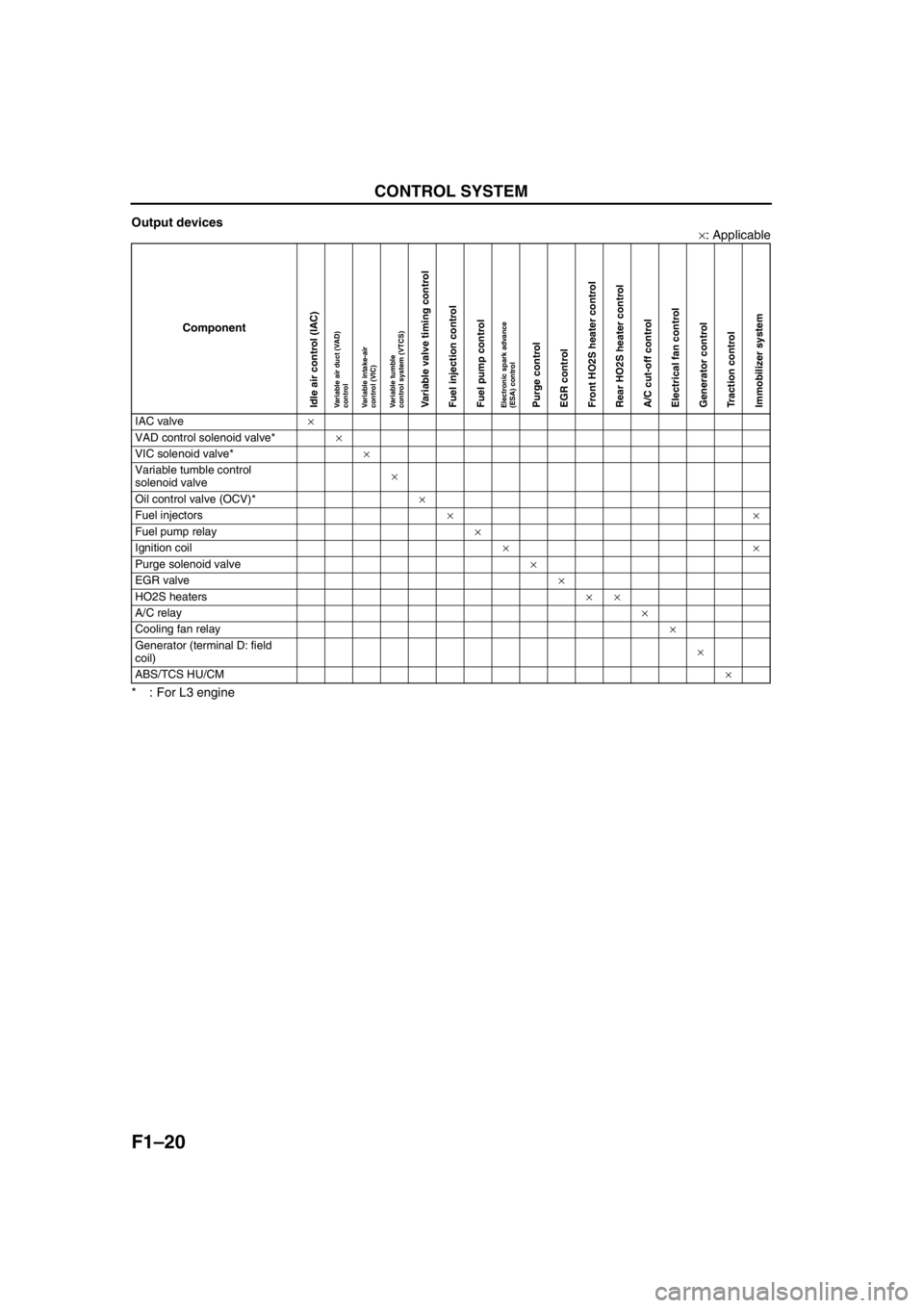
Output devices
×: Applicable
* : For L3 engine
End Of Sie
Component
IAC valve×
VAD control solenoid valve*×
VIC solenoid valve*×
Variable tumble control
solenoid valve×
Oil control valve (OCV)*×
Fuel injectors××
Fuel pump relay×
Ignition coil××
Purge solenoid valve×
EGR valve×
HO2S heaters××
A/C relay×
Cooling fan relay×
Generator (terminal D: field
coil)×
ABS/TCS HU/CM×
Idle air control (IAC)Variable air duct (VAD)
controlVariable intake-air
control (VIC)Variable tumble
control system (VTCS)Variable valve timing controlFuel injection controlFuel pump controlElectronic spark advance
(ESA) controlPurge controlEGR controlFront HO2S heater controlRear HO2S heater controlA/C cut-off controlElectrical fan controlGenerator controlTraction controlImmobilizer system
Page 110 of 909

F1–22
OUTLINE, ENGINE TUNE-UP
SUPPLEMENTAL SERVICE INFORMATIONA6E390218881206•The following changes and/or additions have been made since publication of the Mazda6 Workshop Manual
(1621-10-98E).
Idle speed
•Adjustment procedure has been modified.
Fuel tank
•Removal/installation procedure has been modified.
Fuel pump unit
•Removal/installation procedure has been modified.
Quick release connector (fuel tank side, transfer hose part)
•Removal/installation procedure has been added.
Exhaust system
•Removal/installation procedure has been modified.
PCM
•Inspection procedure has been modified.
On-board diagnostic
•Inspection procedure has been modified.
Troubleshooting
•Inspection procedure has been modified.
End Of Sie
IDLE SPEED INSPECTION (4WD)A6E390802000201
Note
•Ignition timing is not adjustable.
•Ignition timing verification requires WDS or equivalent.
1. Turn off the electrical loads.
2. Warm up the engine as follows.
(1) Start the engine.
(2) Maintain the engine speed at approx. 3,000 rpm until the cooling fans start to operate.
(3) Release the accelerator pedal.
(4) Wait until the cooling fans stop.
3. Verify that the idle speed (WDS: RPM PID) is within the specification using WDS or equivalent.
Idle speed
*1 : Excludes temporary idle speed drop just after the electrical loads are turned on.
*2 : Blower motor is operating at high speed. Headlight switch is turned on. Rear window defroster switch is turned
on. Cooling fans are operating.
End Of Sie
OUTLINE
ENGINE TUNE-UP
Condition
Engine speed (rpm)*1
No load 650—750
Electrical loads*
2 ON650—750
P/S ON 650—750
A/C ON and refrigerant
pressure switch (middle) OFF650—750
A/C ON and refrigerant
pressure switch (middle) ON700—800
Page 122 of 909
F1–34
CONTROL SYSTEM
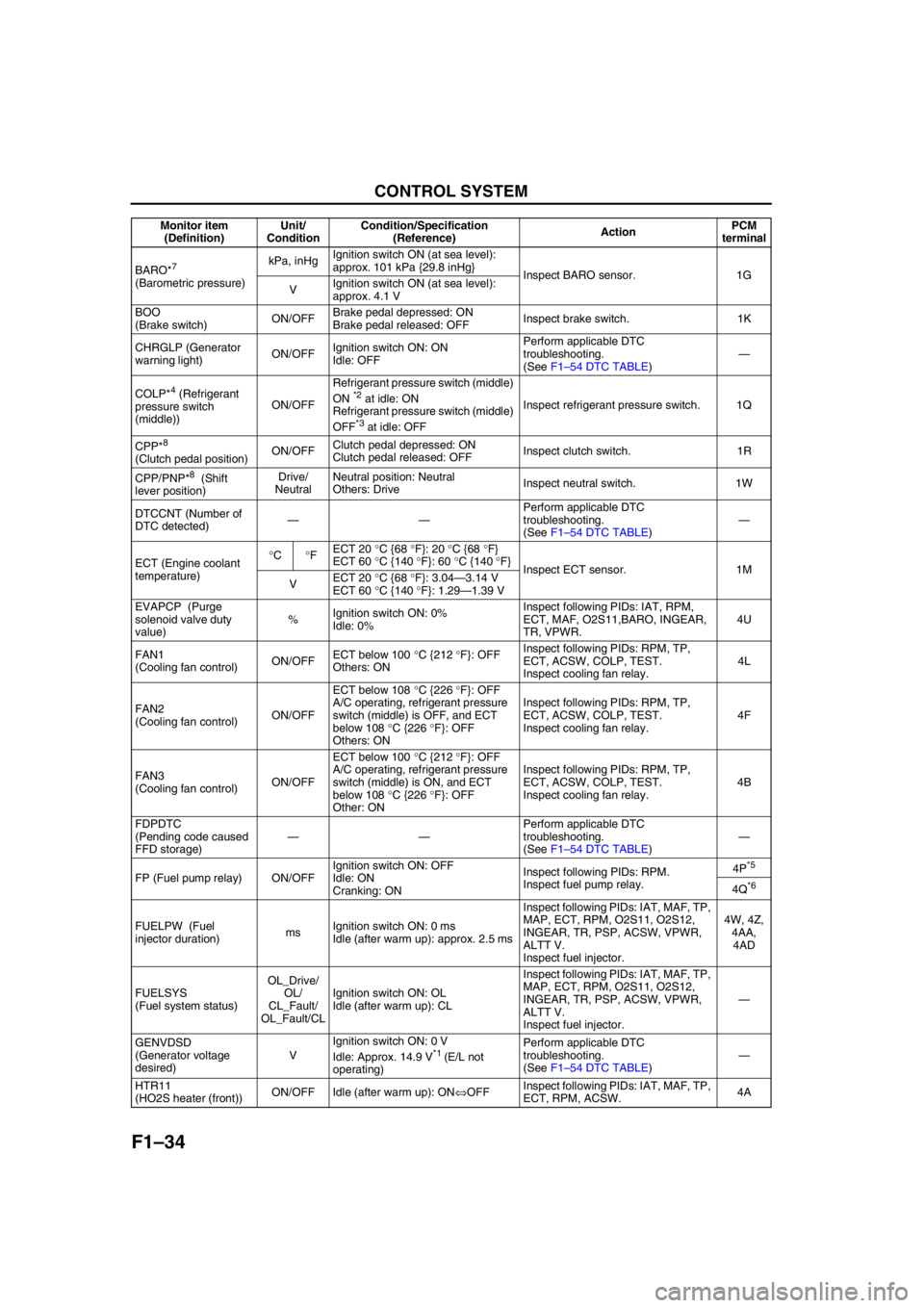
BARO*7
(Barometric pressure)kPa, inHgIgnition switch ON (at sea level):
approx. 101 kPa {29.8 inHg}
Inspect BARO sensor. 1G
VIgnition switch ON (at sea level):
approx. 4.1 V
BOO
(Brake switch)ON/OFFBrake pedal depressed: ON
Brake pedal released: OFFInspect brake switch. 1K
CHRGLP (Generator
warning light)ON/OFFIgnition switch ON: ON
Idle: OFFPerform applicable DTC
troubleshooting.
(See F1–54 DTC TABLE)—
COLP*
4 (Refrigerant
pressure switch
(middle))ON/OFFRefrigerant pressure switch (middle)
ON *2 at idle: ON
Refrigerant pressure switch (middle)
OFF
*3 at idle: OFFInspect refrigerant pressure switch. 1Q
CPP*
8
(Clutch pedal position)ON/OFFClutch pedal depressed: ON
Clutch pedal released: OFFInspect clutch switch. 1R
CPP/PNP*
8 (Shift
lever position)Drive/
NeutralNeutral position: Neutral
Others: DriveInspect neutral switch. 1W
DTCCNT (Number of
DTC detected)——Perform applicable DTC
troubleshooting.
(See F1–54 DTC TABLE)—
ECT (Engine coolant
temperature)°C°FECT 20 °C {68 °F}: 20 °C {68 °F}
ECT 60 °C {140 °F}: 60 °C {140 °F}
Inspect ECT sensor. 1M
VECT 20 °C {68 °F}: 3.04—3.14 V
ECT 60 °C {140 °F}: 1.29—1.39 V
EVAPCP (Purge
solenoid valve duty
value)%Ignition switch ON: 0%
Idle: 0%Inspect following PIDs: IAT, RPM,
ECT, MAF, O2S11,BARO, INGEAR,
TR, VPWR.4U
FAN1
(Cooling fan control)ON/OFFECT below 100 °C {212 °F}: OFF
Others: ONInspect following PIDs: RPM, TP,
ECT, ACSW, COLP, TEST.
Inspect cooling fan relay.4L
FAN2
(Cooling fan control)ON/OFFECT below 108 °C {226 °F}: OFF
A/C operating, refrigerant pressure
switch (middle) is OFF, and ECT
below 108 °C {226 °F}: OFF
Others: ONInspect following PIDs: RPM, TP,
ECT, ACSW, COLP, TEST.
Inspect cooling fan relay.4F
FAN3
(Cooling fan control)ON/OFFECT below 100 °C {212 °F}: OFF
A/C operating, refrigerant pressure
switch (middle) is ON, and ECT
below 108 °C {226 °F}: OFF
Other: ONInspect following PIDs: RPM, TP,
ECT, ACSW, COLP, TEST.
Inspect cooling fan relay.4B
FDPDTC
(Pending code caused
FFD storage)——Perform applicable DTC
troubleshooting.
(See F1–54 DTC TABLE)—
FP (Fuel pump relay) ON/OFFIgnition switch ON: OFF
Idle: ON
Cranking: ONInspect following PIDs: RPM.
Inspect fuel pump relay.4P
*5
4Q*6
FUELPW (Fuel
injector duration)msIgnition switch ON: 0 ms
Idle (after warm up): approx. 2.5 msInspect following PIDs: IAT, MAF, TP,
MAP, ECT, RPM, O2S11, O2S12,
INGEAR, TR, PSP, ACSW, VPWR,
ALTT V.
Inspect fuel injector.4W, 4Z,
4AA,
4AD
FUELSYS
(Fuel system status)OL_Drive/
OL/
CL_Fault/
OL_Fault/CLIgnition switch ON: OL
Idle (after warm up): CLInspect following PIDs: IAT, MAF, TP,
MAP, ECT, RPM, O2S11, O2S12,
INGEAR, TR, PSP, ACSW, VPWR,
ALTT V.
Inspect fuel injector.—
GENVDSD
(Generator voltage
desired)VIgnition switch ON: 0 V
Idle: Approx. 14.9 V
*1 (E/L not
operating)Perform applicable DTC
troubleshooting.
(See F1–54 DTC TABLE)—
HTR11
(HO2S heater (front))ON/OFF Idle (after warm up): ON⇔OFFInspect following PIDs: IAT, MAF, TP,
ECT, RPM, ACSW.4A Monitor item
(Definition)Unit/
ConditionCondition/Specification
(Reference)ActionPCM
terminal
Page 130 of 909
F1–42
CONTROL SYSTEM
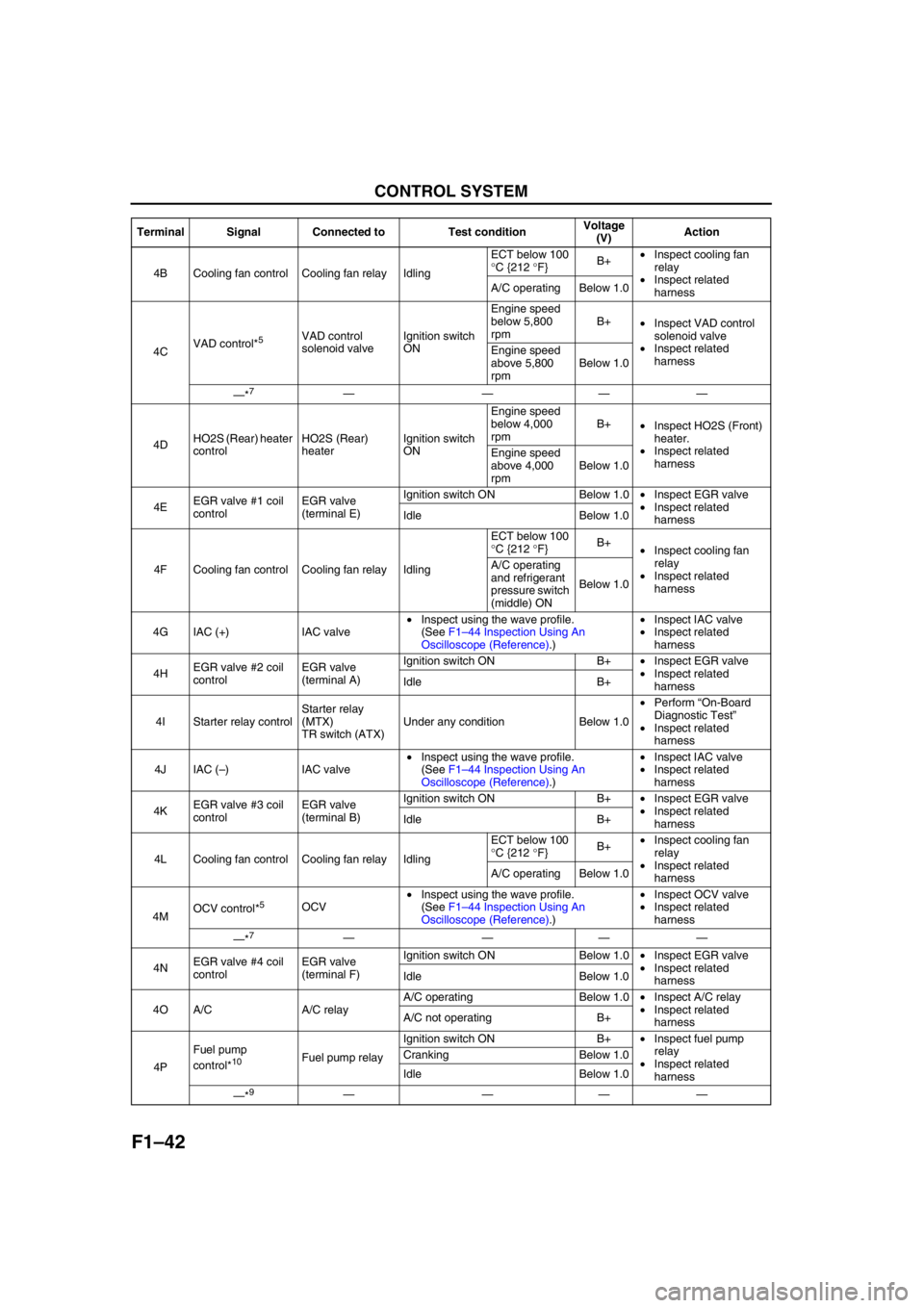
4B Cooling fan control Cooling fan relay IdlingECT below 100
°C {212 °F}B+•Inspect cooling fan
relay
•Inspect related
harness A/C operating Below 1.0
4CVAD control*
5VAD control
solenoid valveIgnition switch
ONEngine speed
below 5,800
rpmB+
•Inspect VAD control
solenoid valve
•Inspect related
harness Engine speed
above 5,800
rpmBelow 1.0
—*
7————
4DHO2S (Rear) heater
controlHO2S (Rear)
heaterIgnition switch
ONEngine speed
below 4,000
rpmB+
•Inspect HO2S (Front)
heater.
•Inspect related
harness Engine speed
above 4,000
rpmBelow 1.0
4EEGR valve #1 coil
controlEGR valve
(terminal E)Ignition switch ON Below 1.0•Inspect EGR valve
•Inspect related
harness Idle Below 1.0
4F Cooling fan control Cooling fan relay IdlingECT below 100
°C {212 °F}B+
•Inspect cooling fan
relay
•Inspect related
harness A/C operating
and refrigerant
pressure switch
(middle) ONBelow 1.0
4G IAC (+) IAC valve•Inspect using the wave profile.
(See F1–44 Inspection Using An
Oscilloscope (Reference).)•Inspect IAC valve
•Inspect related
harness
4HEGR valve #2 coil
controlEGR valve
(terminal A)Ignition switch ON B+•Inspect EGR valve
•Inspect related
harness Idle B+
4I Starter relay controlStarter relay
(MTX)
TR switch (ATX)Under any condition Below 1.0•Perform “On-Board
Diagnostic Test”
•Inspect related
harness
4J IAC (–)IAC valve•Inspect using the wave profile.
(See F1–44 Inspection Using An
Oscilloscope (Reference).)•Inspect IAC valve
•Inspect related
harness
4KEGR valve #3 coil
controlEGR valve
(terminal B)Ignition switch ON B+•Inspect EGR valve
•Inspect related
harness Idle B+
4L Cooling fan control Cooling fan relay IdlingECT below 100
°C {212 °F}B+•Inspect cooling fan
relay
•Inspect related
harness A/C operating Below 1.0
4MOCV control*
5OCV•Inspect using the wave profile.
(See F1–44 Inspection Using An
Oscilloscope (Reference).)•Inspect OCV valve
•Inspect related
harness
—*
7————
4NEGR valve #4 coil
controlEGR valve
(terminal F)Ignition switch ON Below 1.0•Inspect EGR valve
•Inspect related
harness Idle Below 1.0
4O A/C A/C relayA/C operating Below 1.0•Inspect A/C relay
•Inspect related
harness A/C not operating B+
4PFuel pump
control*
10Fuel pump relayIgnition switch ON B+•Inspect fuel pump
relay
•Inspect related
harness Cranking Below 1.0
Idle Below 1.0
—*
9———— Terminal Signal Connected to Test conditionVoltage
(V)Action
Page 141 of 909
ON-BOARD DIAGNOSTIC
F1–53
F1
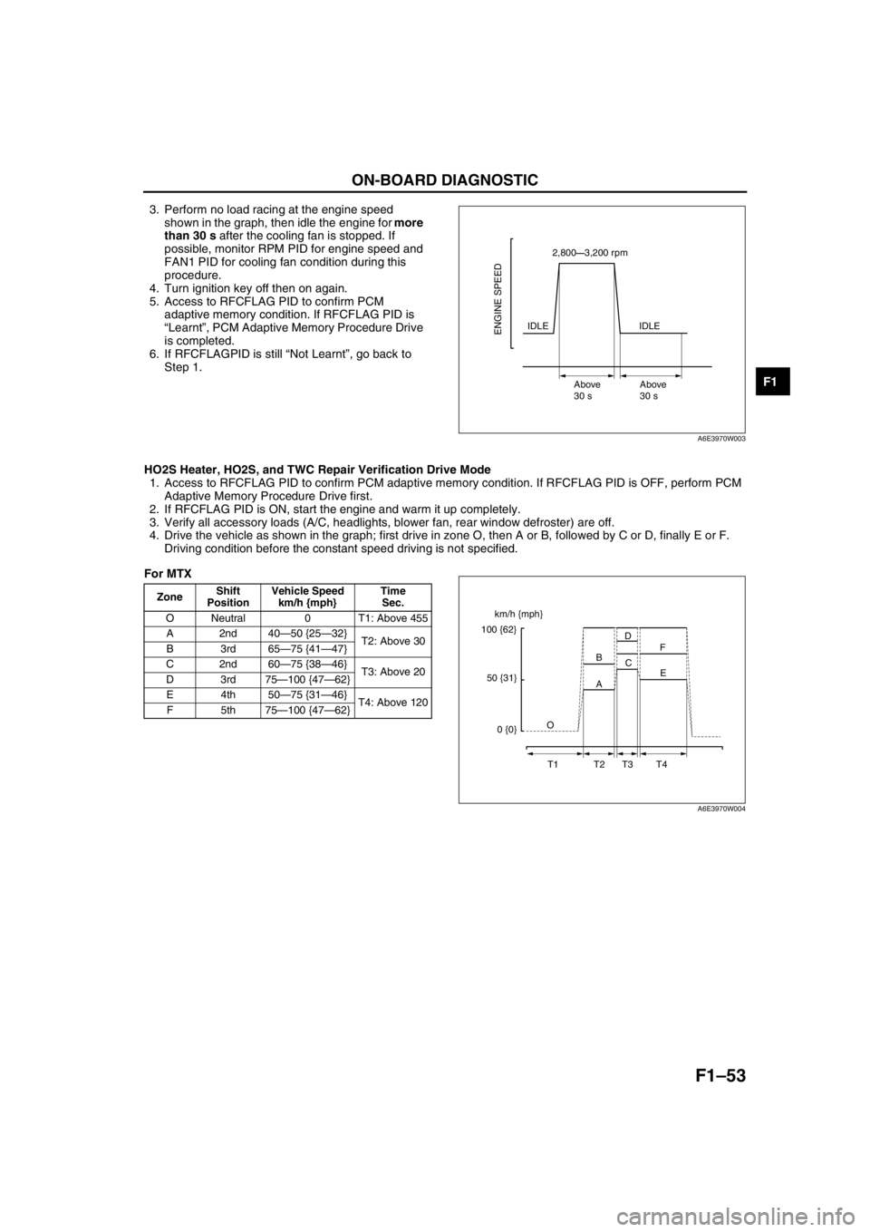
3. Perform no load racing at the engine speed
shown in the graph, then idle the engine for more
than 30 s after the cooling fan is stopped. If
possible, monitor RPM PID for engine speed and
FAN1 PID for cooling fan condition during this
procedure.
4. Turn ignition key off then on again.
5. Access to RFCFLAG PID to confirm PCM
adaptive memory condition. If RFCFLAG PID is
“Learnt”, PCM Adaptive Memory Procedure Drive
is completed.
6. If RFCFLAGPID is still “Not Learnt”, go back to
Step 1.
HO2S Heater, HO2S, and TWC Repair Verification Drive Mode
1. Access to RFCFLAG PID to confirm PCM adaptive memory condition. If RFCFLAG PID is OFF, perform PCM
Adaptive Memory Procedure Drive first.
2. If RFCFLAG PID is ON, start the engine and warm it up completely.
3. Verify all accessory loads (A/C, headlights, blower fan, rear window defroster) are off.
4. Drive the vehicle as shown in the graph; first drive in zone O, then A or B, followed by C or D, finally E or F.
Driving condition before the constant speed driving is not specified.
For MTX
2,800—3,200 rpm
IDLE
Above
30 sAbove
30 s
ENGINE SPEEDIDLE
A6E3970W003
ZoneShift
PositionVehicle Speed
km/h {mph}Time
Sec.
O Neutral 0 T1: Above 455
A2nd40—50 {25—32}
T2: Above 30
B3rd65—75 {41—47}
C2nd60—75 {38—46}
T3: Above 20
D3rd75—100 {47—62}
E4th50—75 {31—46}
T4: Above 120
F5th75—100 {47—62}
km/h {mph}
100 {62}
50 {31}
0 {0}O
T1 T2 T3 T4A BD
C
E F
A6E3970W004
Page 145 of 909

TROUBLESHOOTING
F1–57
F1
ENGINE SYMPTOM TROUBLESHOOTINGA6E398018881201•Confirm trouble symptom using the following diagnostic index, then go to appropriate troubleshooting chart.
Diagnostic Index
End Of Sie
TROUBLESHOOTING
No. TROUBLESHOOTING ITEM DESCRIPTION
1 Melting of main or other fuses—
2 MIL illuminates MIL is illuminated incorrectly.
3 Will not crank Starter does not work.
4Hard to start/long crank/erratic start/erratic
crankStarter cranks engine at normal speed but engine requires excessive
cranking time before starting.
5 Engine stalls. After start/at idle Engine stops unexpectedly at idle and/or after start.
6 Cranks normally but will not start Starter cranks engine at normal speed but engine will not run.
7 Slow return to idle Engine takes more time than normal to return to idle speed.
8 Engine runs rough/rolling idleEngine speed fluctuates between specified idle speed and lower
speed and engine shakes excessively.
9 Fast idle/runs onEngine speed continues at fast idle after warm-up.
Engine runs after ignition switch is turned to off.
10 Low idle/stalls during decelerationEngine stops unexpectedly at beginning of deceleration or recovery
from deceleration.
11Engine stalls/quits. Acceleration/cruiseEngine stops unexpectedly at beginning of acceleration or during
acceleration.
Engine stops unexpectedly while cruising.
Engine runs rough. Acceleration/cruise Engine speed fluctuates during acceleration or cruising.
Misses Acceleration/cruise Engine misses during acceleration or cruising.
Buck/jerkAcceleration/cruise/
decelerationVehicle bucks/jerks during acceleration, cruising, or deceleration.
Hesitation/stumble Acceleration Momentary pause at beginning of acceleration or during acceleration
Surges Acceleration/cruise Momentary minor irregularity in engine output
12 Lack/loss of power Acceleration/cruisePerformance is poor under load.
(e.g., power down when climbing hills)
13 Knocking/pinging Acceleration/cruiseSound is produced when air/fuel mixture is ignited by something other
than spark plug. (e.g., hot spot in combustion chamber)
14 Poor fuel economy Fuel economy is unsatisfactory.
15 Emission compliance Fails emissions test.
16 High oil consumption/leakage Oil consumption is excessive.
17Cooling system
concernsOverheating Engine runs at higher than normal temperature/overheats.
18Cooling system
concernsRuns cold Engine does not reach normal operating temperature.
19 Exhaust smoke Blue, black, or white smoke from exhaust system
20 Fuel odor (in engine compartment) Gasoline fuel smell or visible leakage
21 Engine noise Engine noise from under hood
22 Vibration concerns (engine) Vibration from under hood or driveline
23 A/C does not work sufficiently.A/C compressor magnetic clutch does not engage when A/C is turned
on.
24A/C is always on or A/C compressor runs
continuously.A/C compressor magnetic clutch does not disengage.
25 A/C is not cut off under WOT conditions. A/C compressor magnetic clutch does not disengage under WOT.
26 Exhaust sulphur smell Rotten egg smell (sulphur) from exhaust
27 Constant voltage Incorrect constant voltage
28 Spark plug condition Incorrect spark plug condition
29 ATX concernsUpshift/downshift/
engagementATX concerns not related to engine performance
Page 146 of 909
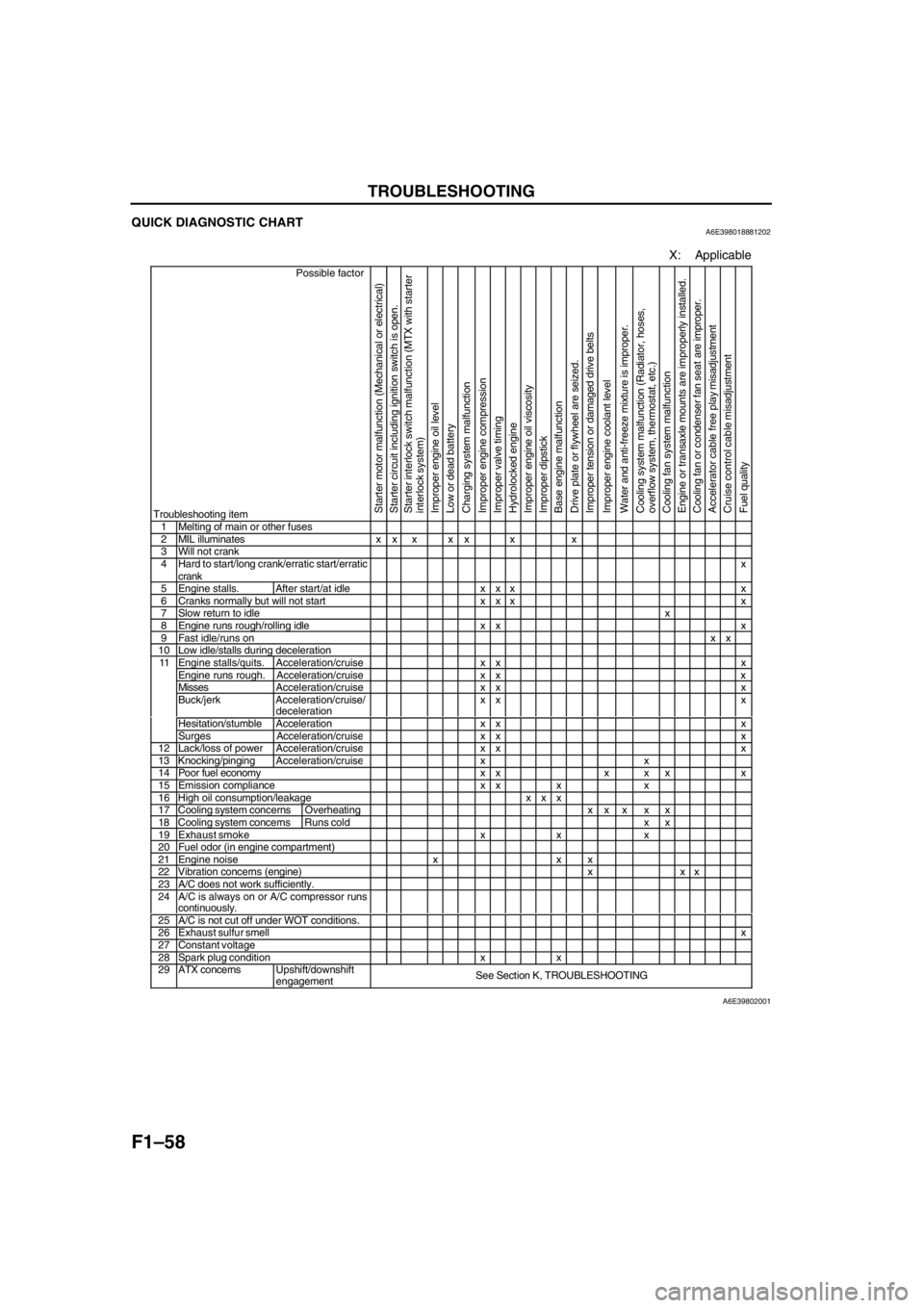
F1–58
TROUBLESHOOTING
QUICK DIAGNOSTIC CHARTA6E398018881202
X: Applicable
Possible factor
Troubleshooting item
Starter motor malfunction (Mechanical or electrical)
Starter circuit including ignition switch is open.
Starter interlock switch malfunction (MTX with starter
interlock system)
Improper engine oil level
Low or dead battery
Charging system malfunction
Improper engine compression
Improper valve timing
Hydrolocked engine
Improper engine oil viscosity
Improper dipstick
Base engine malfunction
Drive plate or flywheel are seized.
Improper tension or damaged drive belts
Improper engine coolant level
Water and anti-freeze mixture is improper.
Cooling system malfunction (Radiator, hoses,
overflow system, thermostat, etc.)
Cooling fan system malfunction
Engine or transaxle mounts are improperly installed.
Cooling fan or condenser fan seat are improper.
Accelerator cable free play misadjustment
Cruise control cable misadjustment
Fuel quality
1 Melting of main or other fuses2 MIL illuminates x x x x x x x3 Will not crank4 Hard to start/long crank/erratic start/erratic
crankx
5 Engine stalls. After start/at idle x x x x6 Cranks normally but will not start x x x x7 Slow return to idlex8 Engine runs rough/rolling idle x x x9 Fast idle/runs onxx10 Low idle/stalls during decelerationEngine stalls/quits. Acceleration/cruise x x xEngine runs rough. Acceleration/cruise x x xMissesAcceleration/cruise x x xBuck/jerk Acceleration/cruise/
decelerationxx x
Hesitation/stumble Acceleration x x x
11
Surges Acceleration/cruis
exx x12 Lack/loss of powerAcceleration/cruisexx x13 Knocking/pingingAcceleration/cruisexx14 Poor fuel economy x x x x x x15 Emission compliance x x x x16 High oil consumption/leakage x x x17 Cooling system concerns Overheatingxx x x x18 Cooling system concernsRuns cold x x19 Exhaust smoke x x x20 Fuel odor (in engine compartment)21 Engine noise x x x22 Vibration concerns (engine) x x x23 A/C does not work sufficiently.24 A/C is always on or A/C compressor runs
continuously.
25 A/C is not cut off under WOT conditions.26 Exhaust sulfur smellx27 Constant voltage28 Spark plug condition x x29 ATX concernsUpshift/downshift
engagementSee Section K, TROUBLESHOOTING
A6E39802001
Page 147 of 909
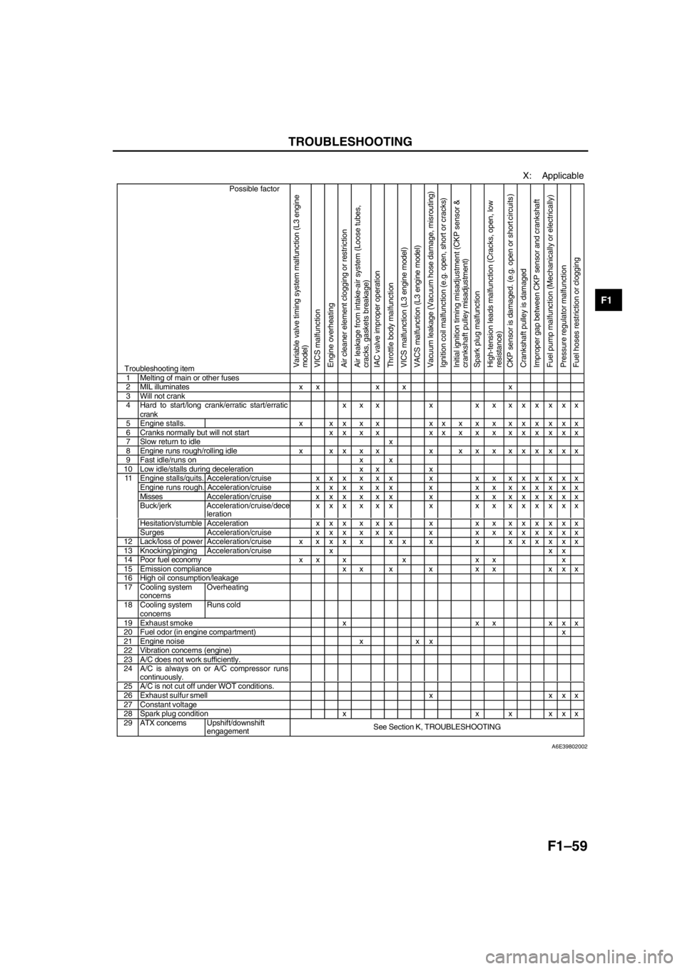
TROUBLESHOOTING
F1–59
F1
X: Applicable
Possible factor
Troubleshooting itemVariable valve timing system malfunction (L3 engine
model)
VICS malfunction
Engine overheating
Air cleaner element clogging or restriction
Air leakage from intake-air system (Loose tubes,
cracks, gaskets breakage)
IAC valve improper operation
Throttle body malfunction
VICS malfunction (L3 engine model)
VACS malfunction (L3 engine model)
Vacuum leakage (Vacuum hose damage, misrouting)
Ignition coil malfunction (e.g. open, short or cracks)
Initial ignition timing misadjustment (CKP sensor &
crankshaft pulley misadjustment)
Spark plug malfunction
High-tension leads malfunction (Cracks, open, low
resistance)
CKP sensor is damaged. (e.g. open or short circuits )
Crankshaft pulley is damaged
Improper gap between CKP sensor and crankshaft
Fuel pump malfunction (Mechanically or electrically)
Pressure regulator malfunction
Fuel hoses restriction or clogging
1 Melting of main or other fuses2 MIL illuminates x x x x x3 Will not crank4 Hard to start/long crank/erratic start/erratic
crankx x x x x x xxxxxx
5 Engine stalls. x x x x x xxxxxxxxxxx6 Cranks normally but will not start x x x x xxxxxxxxxxx7 Slow return to idle x8 Engine runs rough/rolling idle x x x x x x x x xxxxxxx9 Fast idle/runs on x x10 Low idle/stalls during deceleration x x xEngine stalls/quits. Acceleration/cruise x x x x x x x x xxxxxxxEngine runs rough. Acceleration/cruise x x x x x x x x xxxxxxxMissesAcceleration/cruise x x x x x x x x xxxxxxxBuck/jerk Acceleration/cruise/dece
lerationxxx x xx x x x xxxxxx
Hesitation/stumble Acceleration x x x x x x x x xxxxxxx
11
Surges Acceleration/cruise x x x x x x x x xxxxxxx
12 Lack/loss of powerAcceleration/cruise x x x x x x x x xxxxxxx13 Knocking/pingingAcceleration/cruise x x x14 Poor fuel economy x x x x x x x15 Emission compliance x x x x x x x x x16 High oil consumption/leakage17 Cooling system
concernsOverheating
18 Cooling system
concernsRuns cold
19 Exhaust smoke x x x x x x20 Fuel odor (in engine compartment)x21 Engine noise x x x22 Vibration concerns (engine)23 A/C does not work sufficiently.24 A/C is always on or A/C compressor runs
continuously.
25 A/C is not cut off under WOT conditions.26 Exhaust sulfur smell x x x x27 Constant voltage28 Spark plug condition x x x x x x29 ATX concernsUpshift/downshift
engagementSee Section K, TROUBLESHOOTING
A6E39802002