service MAZDA 6 2002 Suplement Owner's Manual
[x] Cancel search | Manufacturer: MAZDA, Model Year: 2002, Model line: 6, Model: MAZDA 6 2002Pages: 909, PDF Size: 17.16 MB
Page 114 of 909
F1–26
FUEL SYSTEM
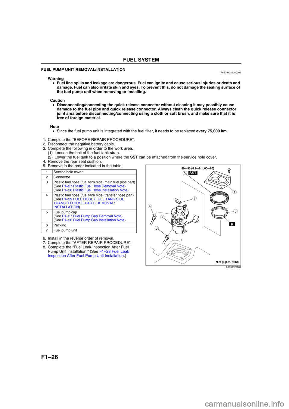
FUEL PUMP UNIT REMOVAL/INSTALLATIONA6E391213350202
Warning
•Fuel line spills and leakage are dangerous. Fuel can ignite and cause serious injuries or death and
damage. Fuel can also irritate skin and eyes. To prevent this, do not damage the sealing surface of
the fuel pump unit when removing or installing.
Caution
•Disconnecting/connecting the quick release connector without cleaning it may possibly cause
damage to the fuel pipe and quick release connector. Always clean the quick release connector
joint area before disconnecting/connecting using a cloth or soft brush, and make sure that it is
free of foreign material.
Note
•Since the fuel pump unit is integrated with the fuel filter, it needs to be replaced every 75,000 km.
1. Complete the “BEFORE REPAIR PROCEDURE”.
2. Disconnect the negative battery cable.
3. Complete the following in order to the work area.
(1) Loosen the bolt of the fuel tank strap.
(2) Lower the fuel tank to a position where the SST can be attached from the service hole cover.
4. Remove the rear seat cushion.
5. Remove in the order indicated in the table.
.
6. Install in the reverse order of removal.
7. Complete the “AFTER REPAIR PROCEDURE”.
8. Complete the “Fuel Leak Inspection After Fuel
Pump Unit Installation.“ (See F1–28 Fuel Leak
Inspection After Fuel Pump Unit Installation.)
1 Service hole cover
2 Connector
3 Plastic fuel hose (fuel tank side, main fuel pipe part)
(See F1–27 Plastic Fuel Hose Removal Note)
(See F1–28 Plastic Fuel Hose Installation Note)
4 Plastic fuel hose (fuel tank side, transfer hose part)
(See F1–29 FUEL HOSE (FUEL TANK SIDE,
TRANSFER HOSE PART) REMOVAL/
INSTALLATION)
5Fuel pump cap
(See F1–27 Fuel Pump Cap Removal Note)
(See F1–28 Fuel Pump Cap Installation Note)
6 Packing
7 Fuel pump unit
3
7
1
4
5
2
6
80—90 {8.2—9.1, 60—66}
R
SST
N·m {kgf·m, ft·lbf}
A6E39122009
Page 150 of 909
F1–62
TROUBLESHOOTING
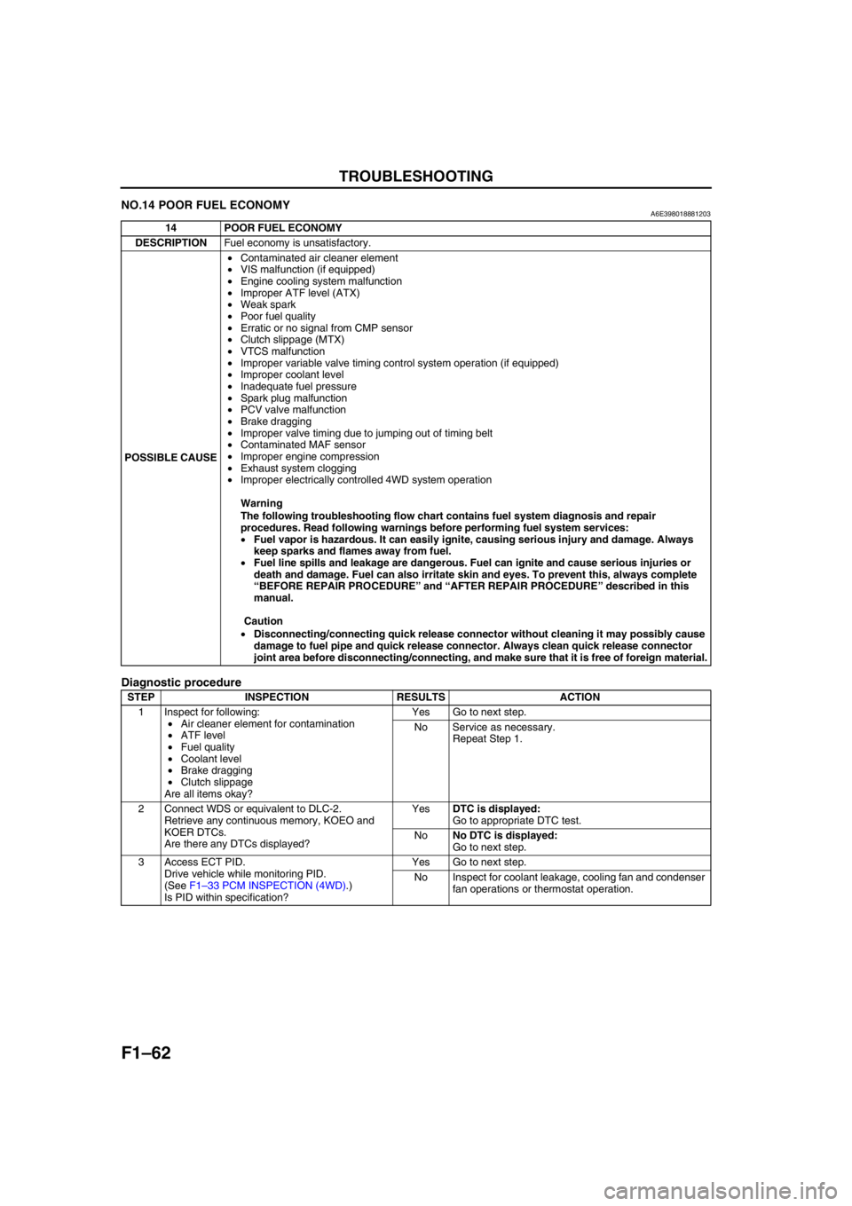
NO.14 POOR FUEL ECONOMYA6E398018881203
Diagnostic procedure
14 POOR FUEL ECONOMY
DESCRIPTIONFuel economy is unsatisfactory.
POSSIBLE CAUSE•Contaminated air cleaner element
•VIS malfunction (if equipped)
•Engine cooling system malfunction
•Improper ATF level (ATX)
•Weak spark
•Poor fuel quality
•Erratic or no signal from CMP sensor
•Clutch slippage (MTX)
•VTCS malfunction
•Improper variable valve timing control system operation (if equipped)
•Improper coolant level
•Inadequate fuel pressure
•Spark plug malfunction
•PCV valve malfunction
•Brake dragging
•Improper valve timing due to jumping out of timing belt
•Contaminated MAF sensor
•Improper engine compression
•Exhaust system clogging
•Improper electrically controlled 4WD system operation
Warning
The following troubleshooting flow chart contains fuel system diagnosis and repair
procedures. Read following warnings before performing fuel system services:
•Fuel vapor is hazardous. It can easily ignite, causing serious injury and damage. Always
keep sparks and flames away from fuel.
•Fuel line spills and leakage are dangerous. Fuel can ignite and cause serious injuries or
death and damage. Fuel can also irritate skin and eyes. To prevent this, always complete
“BEFORE REPAIR PROCEDURE” and “AFTER REPAIR PROCEDURE” described in this
manual.
Caution
•Disconnecting/connecting quick release connector without cleaning it may possibly cause
damage to fuel pipe and quick release connector. Always clean quick release connector
joint area before disconnecting/connecting, and make sure that it is free of foreign material.
STEP INSPECTION RESULTS ACTION
1 Inspect for following:
•Air cleaner element for contamination
•ATF level
•Fuel quality
•Coolant level
•Brake dragging
•Clutch slippage
Are all items okay?Yes Go to next step.
No Service as necessary.
Repeat Step 1.
2 Connect WDS or equivalent to DLC-2.
Retrieve any continuous memory, KOEO and
KOER DTCs.
Are there any DTCs displayed?YesDTC is displayed:
Go to appropriate DTC test.
NoNo DTC is displayed:
Go to next step.
3 Access ECT PID.
Drive vehicle while monitoring PID.
(See F1–33 PCM INSPECTION (4WD).)
Is PID within specification?Yes Go to next step.
No Inspect for coolant leakage, cooling fan and condenser
fan operations or thermostat operation.
Page 151 of 909
TROUBLESHOOTING
F1–63
F1
End Of Sie
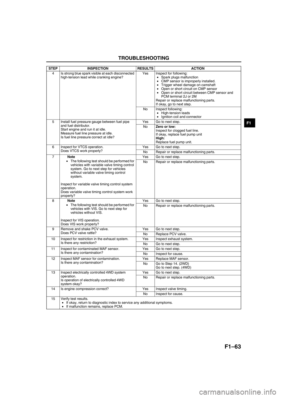
4 Is strong blue spark visible at each disconnected
high-tension lead while cranking engine?Yes Inspect for following:
•Spark plugs malfunction
•CMP sensor is improperly installed.
•Trigger wheel damage on camshaft
•Open or short circuit on CMP sensor
•Open or short circuit between CMP sensor and
PCM terminal 2J or 2M
Repair or replace malfunctioning parts.
If okay, go to next step.
No Inspect following:
•High-tension leads
•Ignition coil and connector
5 Install fuel pressure gauge between fuel pipe
and fuel distributor.
Start engine and run it at idle.
Measure fuel line pressure at idle.
Is fuel line pressure correct at idle?Yes Go to next step.
NoZero or low:
Inspect for clogged fuel line.
If okay, replace fuel pump unit
High:
Replace fuel pump unit.
6 Inspect for VTCS operation.
Does VTCS work properly?Yes Go to next step.
No Repair or replace malfunctioning parts.
7Note
•The following test should be performed for
vehicles with variable valve timing control
system. Go to next step for vehicles
without variable valve timing control
system.
Inspect for variable valve timing control system
operation.
Does variable valve timing control system work
properly?Yes Go to next step.
No Repair or replace malfunctioning parts.
8Note
•The following test should be performed for
vehicles with VIS. Go to next step for
vehicles without VIS.
Inspect for VIS operation.
Does VIS work properly?Yes Go to next step.
No Repair or replace malfunctioning parts.
9 Remove and shake PCV valve.
Does PCV valve rattle?Yes Go to next step.
No Replace PCV valve.
10 Inspect for restriction in the exhaust system.
Is there any restriction?Yes Inspect exhaust system.
No Go to next step.
11 Inspect for contaminated MAF sensor.
Is there any contamination?Yes Go to next step.
No Inspect for cause.
12 Inspect MAF sensor for contamination.
Is there any contamination?Yes Replace MAF sensor.
No Go to Step 14. (2WD)
Go to next step. (4WD)
13 Inspect electrically controlled 4WD system
operation.
Is operation of electrically controlled 4WD
system okay?Yes Go to next step.
No Repair or replace malfunctioning parts.
14 Is engine compression correct? Yes Inspect valve timing.
No Inspect for cause.
15 Verify test results.
•If okay, return to diagnostic index to service any additional symptoms.
•If malfunction remains, replace PCM. STEP INSPECTION RESULTS ACTION
Page 152 of 909
F1–64
TROUBLESHOOTING
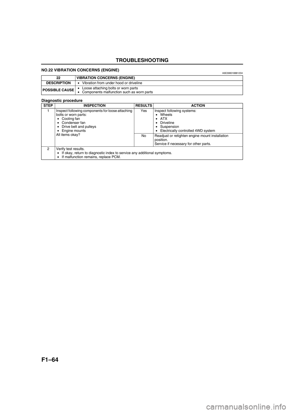
NO.22 VIBRATION CONCERNS (ENGINE)A6E398018881204
Diagnostic procedure
End Of Sie
22 VIBRATION CONCERNS (ENGINE)
DESCRIPTION•Vibration from under hood or driveline
POSSIBLE CAUSE•Loose attaching bolts or worn parts
•Components malfunction such as worn parts
STEP INSPECTION RESULTS ACTION
1 Inspect following components for loose attaching
bolts or worn parts:
•Cooling fan
•Condenser fan
•Drive belt and pulleys
•Engine mounts
All items okay?Yes Inspect following systems:
•Wheels
•ATX
•Driveline
•Suspension
•Electrically controlled 4WD system
No Readjust or retighten engine mount installation
position.
Service if necessary for other parts.
2 Verify test results.
•If okay, return to diagnostic index to service any additional symptoms.
•If malfunction remains, replace PCM.
Page 153 of 909
![MAZDA 6 2002 Suplement Owners Manual F2–1
F2
F2FUEL AND EMISSION CONTROL SYSTEMS
[MZR-CD (RF Turbo)]
OUTLINE.............................................................. F2-3
OUTLINE OF CONSTRUCTION ....................... F2-3
FEATUR MAZDA 6 2002 Suplement Owners Manual F2–1
F2
F2FUEL AND EMISSION CONTROL SYSTEMS
[MZR-CD (RF Turbo)]
OUTLINE.............................................................. F2-3
OUTLINE OF CONSTRUCTION ....................... F2-3
FEATUR](/img/28/57057/w960_57057-152.png)
F2–1
F2
F2FUEL AND EMISSION CONTROL SYSTEMS
[MZR-CD (RF Turbo)]
OUTLINE.............................................................. F2-3
OUTLINE OF CONSTRUCTION ....................... F2-3
FEATURES ........................................................ F2-3
SPECIFICATIONS ............................................. F2-3
CONTROL SYSTEM DIAGRAM ........................ F2-4
CONTROL SYSTEM WIRING DIAGRAM.......... F2-5
INTAKE-AIR SYSTEM.......................................... F2-8
OUTLINE ........................................................... F2-8
STRUCTURAL VIEW......................................... F2-9
FUEL SYSTEM................................................... F2-10
OUTLINE ......................................................... F2-10
STRUCTURAL VIEW....................................... F2-11
EXHAUST SYSTEM........................................... F2-13
OUTLINE ......................................................... F2-13
STRUCTURAL VIEW....................................... F2-13
EMISSION SYSTEM........................................... F2-14
OUTLINE ......................................................... F2-14
STRUCTURAL VIEW....................................... F2-15
WARM UP OXIDATION CATALYTIC
CONVERTER DESCRIPTION ...................... F2-16
CONTROL SYSTEM........................................... F2-16
OUTLINE ......................................................... F2-16
STRUCTURAL VIEW....................................... F2-18
BLOCK DIAGRAM ........................................... F2-20
CONTROL DEVICE AND CONTROL
RELATIONSHIP CHART .............................. F2-22
CRUISE CONTROL SYSTEM ......................... F2-23
CONTROLLER AREA NETWORK (CAN) ....... F2-24
ON-BOARD DIAGNOSTIC................................. F2-24
OUTLINE ......................................................... F2-24
DTC.................................................................. F2-24
KOEO/KOER SELF-TEST ............................... F2-26
PID/DATA MONITOR AND RECORD ............. F2-27
SIMULATION TEST ......................................... F2-27
LOCATION INDEX............................................. F2-28
INTAKE-AIR SYSTEM ..................................... F2-28
FUEL SYSTEM ................................................ F2-29
EMISSION SYSTEM........................................ F2-31
CONTROL SYSTEM........................................ F2-32
ENGINE TUNE-UP............................................. F2-34
ENGINE TUNE-UP PREPARATION ............... F2-34
IDLE SPEED INSPECTION ............................. F2-34
CORRECTION PROCEDURE ......................... F2-34
INTAKE-AIR SYSTEM........................................ F2-35
VACUUM TUBE ROUTING DIAGRAM............ F2-35
INTAKE-AIR SYSTEM
REMOVAL/INSTALLATION .......................... F2-36
AIR CLEANER ELEMENT INSPECTION ........ F2-37
TURBOCHARGER INSPECTION ................... F2-38
GUIDE BLADE ACTUATOR INSPECTION ..... F2-39
VARIABLE BOOST CONTROL (VBC)
SOLENOID VALVE INSPECTION ................ F2-40VARIABLE BOOST CONTROL (VBC)
CHECK VALVE INSPECTION ...................... F2-41
VARIABLE SWIRL CONTROL (VSC)
VALVE ACTUATOR INSPECTION ............... F2-41
VARIABLE SWIRL CONTROL (VSC)
SOLENOID VALVE INSPECTION ................ F2-42
GLOW PLUG REMOVAL/INSTALLATION ...... F2-42
GLOW PLUG INSPECTION ............................ F2-43
GLOW PLUG LEAD INSPECTION .................. F2-43
ACCELERATOR PEDAL COMPONENT
REMOVAL/INSTALLATION .......................... F2-44
ACCELERATOR PEDAL COMPONENT
DISASSEMBLY/ASSEMBLY ........................ F2-44
FUEL SYSTEM................................................... F2-45
BEFORE REPAIR PROCEDURE .................... F2-45
AFTER REPAIR PROCEDURE ....................... F2-45
FUEL TANK REMOVAL/INSTALLATION ........ F2-45
FUEL TANK INSPECTION .............................. F2-49
NONRETURN VALVE INSPECTION............... F2-50
FUEL FILTER COMPONENT
REMOVAL/INSTALLATION .......................... F2-50
FUEL FILTER COMPONENT
DISASSEMBLY/ASSEMBLY ........................ F2-51
FUEL WARMER INSPECTION........................ F2-51
SEDIMENTOR WATER DRAINING................. F2-52
SEDIMENTOR SWITCH INSPECTION ........... F2-52
SUPPLY PUMP REMOVAL/INSTALLATION .. F2-53
SUPPLY PUMP INSPECTION......................... F2-54
SUCTION CONTROL VALVE INSPECTION ... F2-54
COMMON RAIL INSPECTION ........................ F2-54
FUEL INJECTOR REMOVAL/INSTALLATION F2-55
FUEL INJECTOR INSPECTION ...................... F2-56
EXHAUST SYSTEM........................................... F2-57
EXHAUST SYSTEM INSPECTION ................. F2-57
EXHAUST SYSTEM
REMOVAL/INSTALLATION .......................... F2-57
EMISSION SYSTEM........................................... F2-59
EGR VALVE REMOVAL/INSTALLATION........ F2-59
EGR VALVE INSPECTION .............................. F2-59
EGR SOLENOID VALVE (VACUUM)
INSPECTION ................................................ F2-60
EGR SOLENOID VALVE (VENT)
INSPECTION ................................................ F2-60
EGR CONTROL SOLENOID VALVE
INSPECTION ................................................ F2-61
INTAKE SHUTTER VALVE ACTUATOR
INSPECTION ................................................ F2-62
INTAKE SHUTTER SOLENOID VALVE
INSPECTION ................................................ F2-63
CONTROL SYSTEM........................................... F2-64
PCM REMOVAL/INSTALLATION .................... F2-64
PCM INSPECTION .......................................... F2-65
PCM CONFIGURATION .................................. F2-68
CLUTCH SWITCH INSPECTION .................... F2-68
NEUTRAL SWITCH INSPECTION .................. F2-69
IDLE SWITCH INSPECTION ........................... F2-70
IDLE SWITCH ADJUSTMENT ......................... F2-71
ACCELERATOR POSITION SENSOR
INSPECTION ................................................ F2-72
ACCELERATOR POSITION SENSOR
ADJUSTMENT .............................................. F2-73 FEATURES
SERVICE
Page 155 of 909
OUTLINE
F2–3
F2
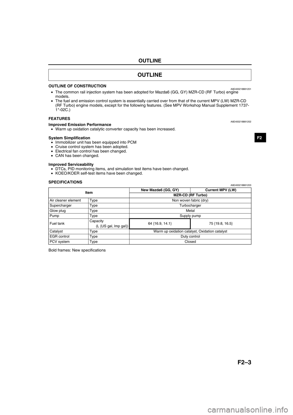
OUTLINE OF CONSTRUCTIONA6E400218881201•The common rail injection system has been adopted for Mazda6 (GG, GY) MZR-CD (RF Turbo) engine
models.
•The fuel and emission control system is essentially carried over from that of the current MPV (LW) MZR-CD
(RF Turbo) engine models, except for the following features. (See MPV Workshop Manual Supplement 1737-
1*-02C.)
End Of Sie
FEATURESA6E400218881202Improved Emission Performance
•Warm up oxidation catalytic converter capacity has been increased.
System Simplification
•Immobilizer unit has been equipped into PCM
•Cruise control system has been adopted.
•Electrical fan control has been changed.
•CAN has been changed.
Improved Serviceability
•DTCs, PID monitoring items, and simulation test items have been changed.
•KOEO/KOER self-test items have been changed.
End Of Sie
SPECIFICATIONSA6E400218881203
Bold frames: New specifications
End Of Sie
OUTLINE
ItemNew Mazda6 (GG, GY) Current MPV (LW)
MZR-CD (RF Turbo)
Air cleaner element Type Non woven fabric (dry)
Supercharger Type Turbocharger
Glow plug Type Metal
Pump Type Supply pump
Fuel tankCapacity
64 {16.9, 14.1} 75 {19.8, 16.5}
(L {US gal, lmp gal})
Catalyst Type Warm up oxidation catalyst, Oxidation catalyst
EGR control Type Duty control
PCV system Type Closed
Page 198 of 909
F2–46
FUEL SYSTEM
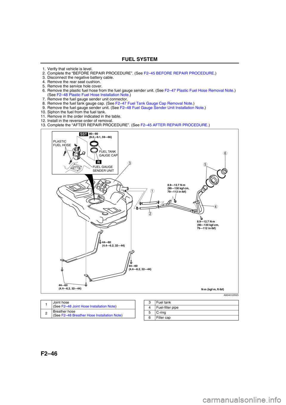
1. Verify that vehicle is level.
2. Complete the “BEFORE REPAIR PROCEDURE”. (See F2–45 BEFORE REPAIR PROCEDURE.)
3. Disconnect the negative battery cable.
4. Remove the rear seat cushion.
5. Remove the service hole cover.
6. Remove the plastic fuel hose from the fuel gauge sender unit. (See F2–47 Plastic Fuel Hose Removal Note.)
(See F2–48 Plastic Fuel Hose Installation Note.)
7. Remove the fuel gauge sender unit connector.
8. Remove the fuel tank gauge cap. (See F2–47 Fuel Tank Gauge Cap Removal Note.)
9. Remove the fuel gauge sender unit. (See F2–48 Fuel Gauge Sender Unit Installation Note.)
10. Siphon the fuel from the fuel tank.
11. Remove in the order indicated in the table.
12. Install in the reverse order of removal.
13. Complete the “AFTER REPAIR PROCEDURE”. (See F2–45 AFTER REPAIR PROCEDURE.)
.
44—60
{4.4—6.2, 32—44}44—60
{4.4—6.2, 32—44} 44—60
{4.4—6.2, 32—44}
N·m {kgf·m, ft·lbf}
8.9—12.7 N·m
{90—130 kgf·cm,
79—112 in·lbf}
8.9—12.7 N·m
{90—130 kgf·cm,
79—112 in·lbf}
5
4
3
2
1
6
80—90
{8.2—9.1, 59—66}
R
PLASTIC
FUEL HOSE
FUEL GAUGE
SENDER UNITFUEL TANK
GAUGE CAP
SST
A6E40122025
1Joint hose
(See F2–48 Joint Hose Installation Note)
2Breather hose
(See F2–48 Breather Hose Installation Note)3 Fuel tank
4 Fuel-filler pipe
5 C-ring
6 Filler cap
Page 205 of 909
FUEL SYSTEM
F2–53
F2
SUPPLY PUMP REMOVAL/INSTALLATIONA6E401213350201
Caution
•Fuel line spills and leakage on the parts are dangerous. Fuel can ignite and also deteriorate the
parts. To prevent this, always cover the mouths of the removed parts in the fuel system with rags
to soak up the fuel.
•To prevent the fuel injection pipe from clogging, be careful that foreign material has not entered
the pipe. Also, be sure to tighten the bolts with the specified tightening torque when installing the
fuel injection pipe.
•To prevent fuel leakage, follow the procedure indicated in the workshop manual when removing
and installing the fuel injector.
•The fuel injection pipe can be removed and reinstalled up to five times. Be sure to record in the
service record when removing and installing the fuel injection pipe. If removing it for the sixth
time, be sure to replace it with a new one.
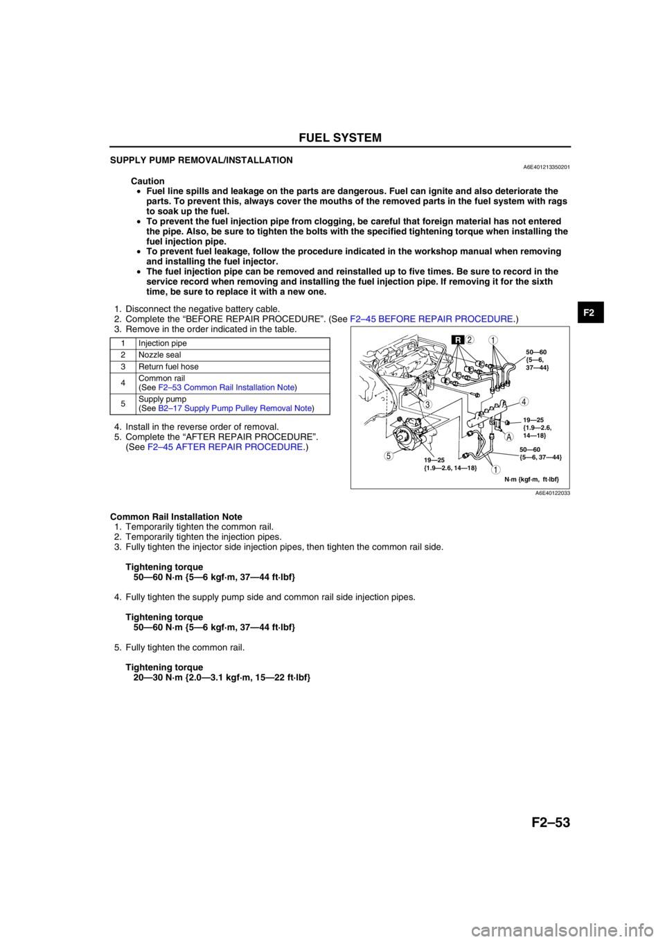
1. Disconnect the negative battery cable.
2. Complete the “BEFORE REPAIR PROCEDURE”. (See F2–45 BEFORE REPAIR PROCEDURE.)
3. Remove in the order indicated in the table.
.
4. Install in the reverse order of removal.
5. Complete the “AFTER REPAIR PROCEDURE”.
(See F2–45 AFTER REPAIR PROCEDURE.)
Common Rail Installation Note
1. Temporarily tighten the common rail.
2. Temporarily tighten the injection pipes.
3. Fully tighten the injector side injection pipes, then tighten the common rail side.
Tightening torque
50—60 N·m {5—6 kgf·m, 37—44 ft·lbf}
4. Fully tighten the supply pump side and common rail side injection pipes.
Tightening torque
50—60 N·m {5—6 kgf·m, 37—44 ft·lbf}
5. Fully tighten the common rail.
Tightening torque
20—30 N·m {2.0—3.1 kgf·m, 15—22 ft·lbf}
End Of Sie
1 Injection pipe
2 Nozzle seal
3 Return fuel hose
4Common rail
(See F2–53 Common Rail Installation Note)
5Supply pump
(See B2–17 Supply Pump Pulley Removal Note)
19—25
{1.9—2.6, 14—18}19—25
{1.9—2.6,
14—18} 50—60
{5—6,
37—44}
50—60
{5—6, 37—44}
N·m {kgf·m, ft·lbf}
A
R
A
5
43
12
1
A6E40122033
Page 207 of 909
FUEL SYSTEM
F2–55
F2
FUEL INJECTOR REMOVAL/INSTALLATIONA6E401213250201
Caution
•Fuel line spills and leakage on the parts are dangerous. Fuel can ignite and also deteriorate the
parts. To prevent this, always cover the mouths of the removed parts in the fuel system with rags
to soak up the fuel.
•To prevent the fuel injection pipe from clogging, be careful that foreign material has not entered
the pipe. Also, be sure to tighten the bolts with the specified tightening torque when installing the
fuel injection pipe.
•To prevent fuel leakage, follow the procedure indicated in the workshop manual when removing
and installing the fuel injector.
•The fuel injection pipe can be removed and reinstalled up to five times. Be sure to record in the
service record when removing and installing the fuel injection pipe. If removing it for the sixth
time, be sure to replace it with a new one.
Note
•Perform “Correction after Parts Installation” after replacing fuel injector. (See F2–34 Correction after Parts
Installation.)
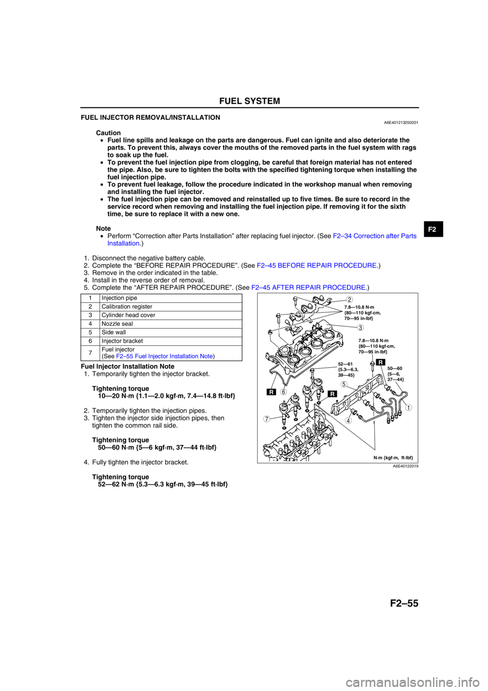
1. Disconnect the negative battery cable.
2. Complete the “BEFORE REPAIR PROCEDURE”. (See F2–45 BEFORE REPAIR PROCEDURE.)
3. Remove in the order indicated in the table.
4. Install in the reverse order of removal.
5. Complete the “AFTER REPAIR PROCEDURE”. (See F2–45 AFTER REPAIR PROCEDURE.)
.
Fuel Injector Installation Note
1. Temporarily tighten the injector bracket.
Tightening torque
10—20 N·m {1.1—2.0 kgf·m, 7.4—14.8 ft·lbf}
2. Temporarily tighten the injection pipes.
3. Tighten the injector side injection pipes, then
tighten the common rail side.
Tightening torque
50—60 N·m {5—6 kgf·m, 37—44 ft·lbf}
4. Fully tighten the injector bracket.
Tightening torque
52—62 N·m {5.3—6.3 kgf·m, 39—45 ft·lbf}
1 Injection pipe
2 Calibration register
3 Cylinder head cover
4 Nozzle seal
5Side wall
6 Injector bracket
7Fuel injector
(See F2–55 Fuel Injector Installation Note)
RR
R50—60
{5—6,
37—44} 52—61
{5.3—6.3,
39—45}
N·m {kgf·m, ft·lbf} 7.8—10.8 N·m
{80—110 kgf·cm,
70—95 in·lbf}
7.8—10.8 N·m
{80—110 kgf·cm,
70—95 in·lbf}
5
4
3
1
2
7
6
A6E40122019
Page 237 of 909
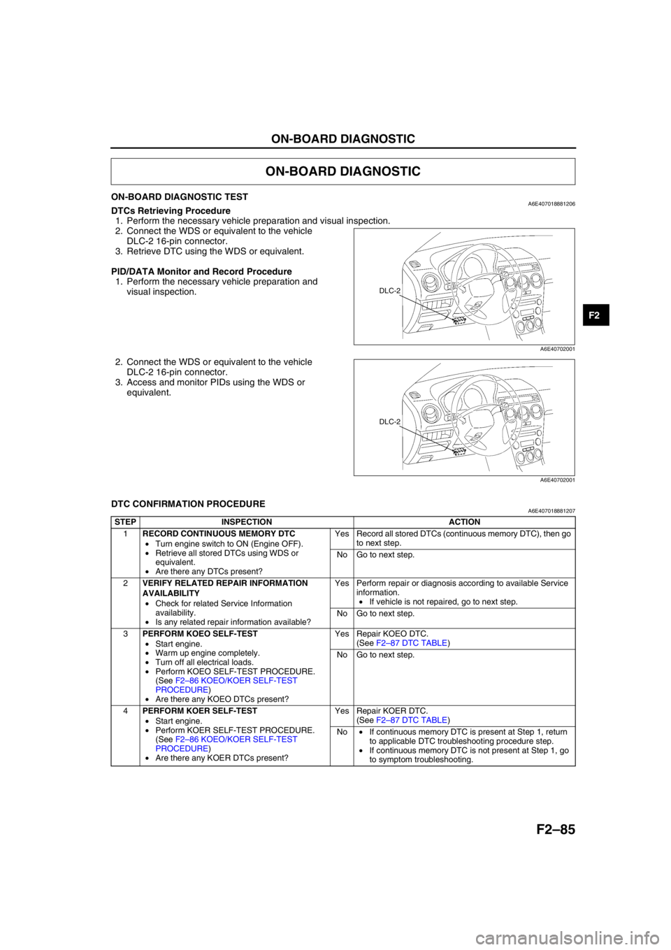
ON-BOARD DIAGNOSTIC
F2–85
F2
ON-BOARD DIAGNOSTIC TESTA6E407018881206DTCs Retrieving Procedure
1. Perform the necessary vehicle preparation and visual inspection.
2. Connect the WDS or equivalent to the vehicle
DLC-2 16-pin connector.
3. Retrieve DTC using the WDS or equivalent.
PID/DATA Monitor and Record Procedure
1. Perform the necessary vehicle preparation and
visual inspection.
2. Connect the WDS or equivalent to the vehicle
DLC-2 16-pin connector.
3. Access and monitor PIDs using the WDS or
equivalent.
End Of Sie
DTC CONFIRMATION PROCEDUREA6E407018881207
End Of Sie
ON-BOARD DIAGNOSTIC
DLC-2
A6E40702001
DLC-2
A6E40702001
STEP INSPECTION ACTION
1RECORD CONTINUOUS MEMORY DTC
•Turn engine switch to ON (Engine OFF).
•Retrieve all stored DTCs using WDS or
equivalent.
•Are there any DTCs present?Yes Record all stored DTCs (continuous memory DTC), then go
to next step.
No Go to next step.
2VERIFY RELATED REPAIR INFORMATION
AVAILABILITY
•Check for related Service Information
availability.
•Is any related repair information available?Yes Perform repair or diagnosis according to available Service
information.
•If vehicle is not repaired, go to next step.
No Go to next step.
3PERFORM KOEO SELF-TEST
•Start engine.
•Warm up engine completely.
•Turn off all electrical loads.
•Perform KOEO SELF-TEST PROCEDURE.
(See F2–86 KOEO/KOER SELF-TEST
PROCEDURE)
•Are there any KOEO DTCs present?Yes Repair KOEO DTC.
(See F2–87 DTC TABLE)
No Go to next step.
4PERFORM KOER SELF-TEST
•Start engine.
•Perform KOER SELF-TEST PROCEDURE.
(See F2–86 KOEO/KOER SELF-TEST
PROCEDURE)
•Are there any KOER DTCs present?Yes Repair KOER DTC.
(See F2–87 DTC TABLE)
No•If continuous memory DTC is present at Step 1, return
to applicable DTC troubleshooting procedure step.
•If continuous memory DTC is not present at Step 1, go
to symptom troubleshooting.