ECU MAZDA 6 2002 Suplement Service Manual
[x] Cancel search | Manufacturer: MAZDA, Model Year: 2002, Model line: 6, Model: MAZDA 6 2002Pages: 909, PDF Size: 17.16 MB
Page 682 of 909
M–52
REAR DIFFERENTIAL
Coupling Component and Rear Differential Component Removal/installation Note
Warning
•Make sure that the coupling component and rear differential component are securely supported
by the jack. If the coupling component and rear differential component fall, it could cause death,
serious injury, or vehicle damage.
1. Make sure that the coupling component and rear
differential component are securely supported by
the jack, and remove/install the component by
operating the jack gradually.
End Of Sie
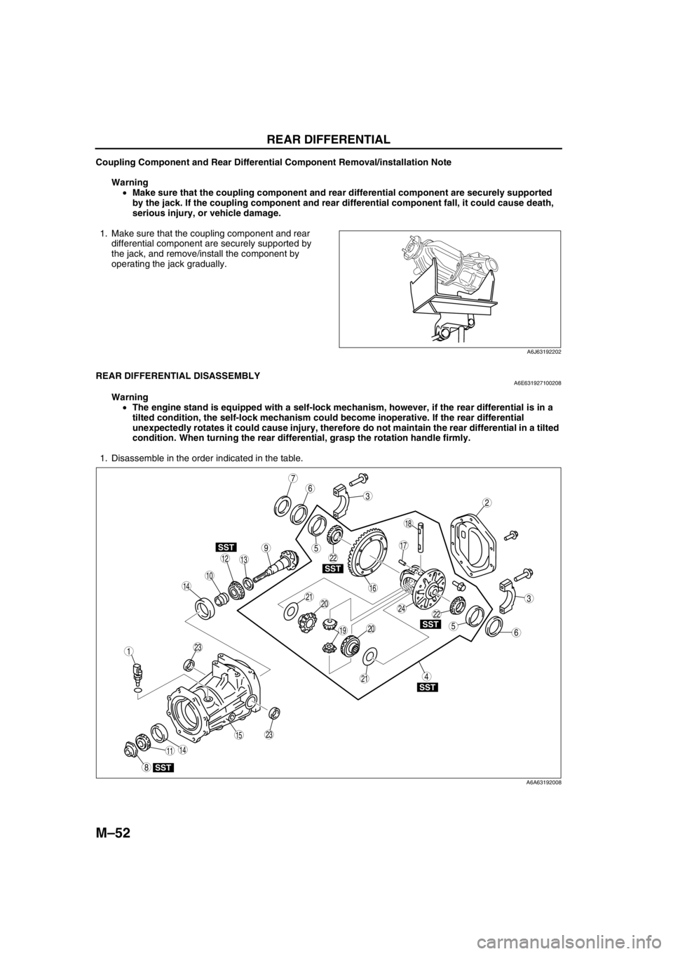
REAR DIFFERENTIAL DISASSEMBLYA6E631927100208
Warning
•The engine stand is equipped with a self-lock mechanism, however, if the rear differential is in a
tilted condition, the self-lock mechanism could become inoperative. If the rear differential
unexpectedly rotates it could cause injury, therefore do not maintain the rear differential in a tilted
condition. When turning the rear differential, grasp the rotation handle firmly.
1. Disassemble in the order indicated in the table.
.
A6J63192202
9
7
3
10
SST
SST
SST
SST
SST
6
18
14
14
1312
8
5
5
4
3
1
2
19
17
15
16
11
20
2024
23
23
21
21
22
22
6
A6A63192008
Page 685 of 909
REAR DIFFERENTIAL
M–55
M
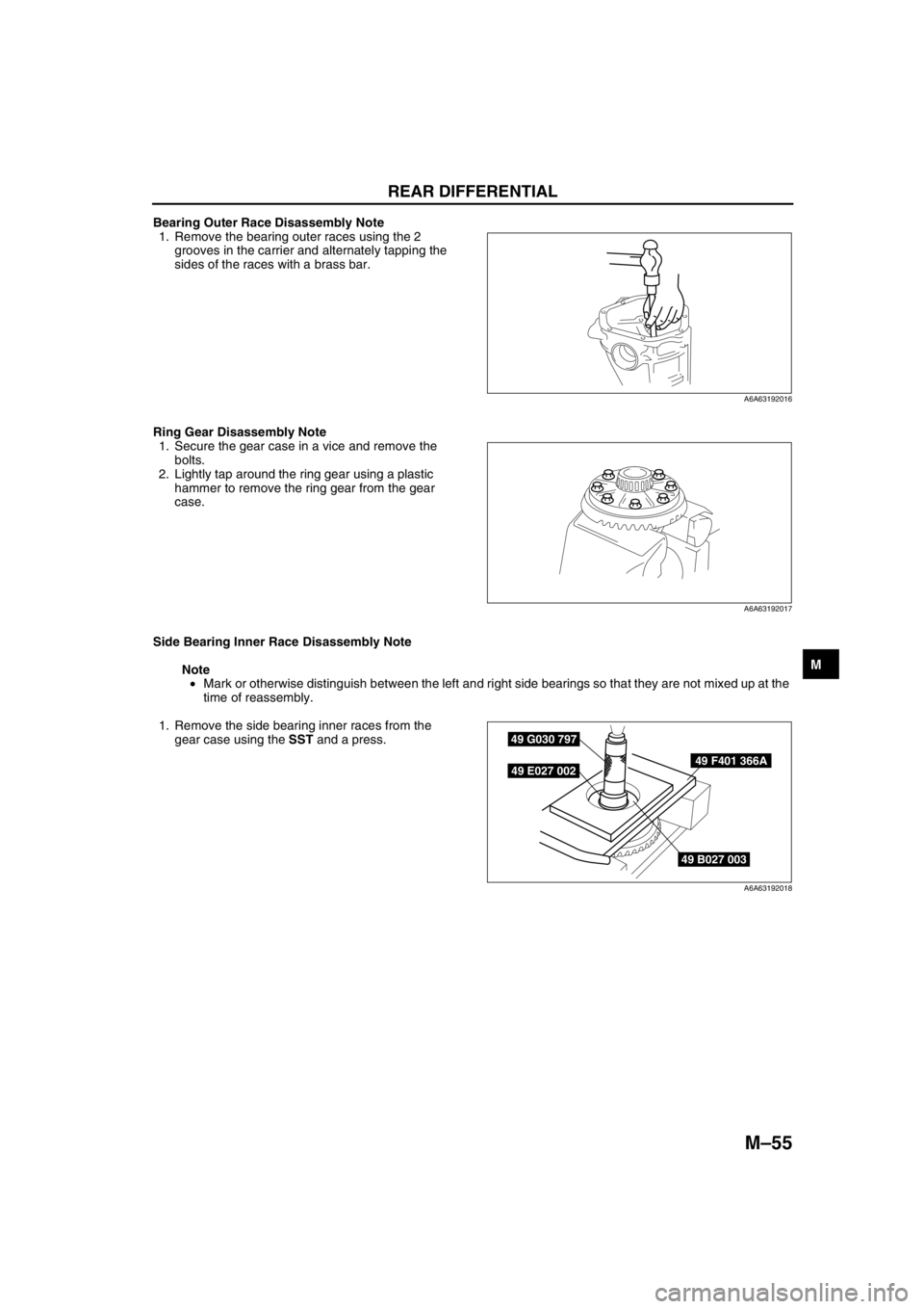
Bearing Outer Race Disassembly Note
1. Remove the bearing outer races using the 2
grooves in the carrier and alternately tapping the
sides of the races with a brass bar.
Ring Gear Disassembly Note
1. Secure the gear case in a vice and remove the
bolts.
2. Lightly tap around the ring gear using a plastic
hammer to remove the ring gear from the gear
case.
Side Bearing Inner Race Disassembly Note
Note
•Mark or otherwise distinguish between the left and right side bearings so that they are not mixed up at the
time of reassembly.
1. Remove the side bearing inner races from the
gear case using the SST and a press.
End Of Sie
A6A63192016
A6A63192017
49 B027 003
49 F401 366A
49 G030 797
49 E027 002
A6A63192018
Page 687 of 909
REAR DIFFERENTIAL
M–57
M
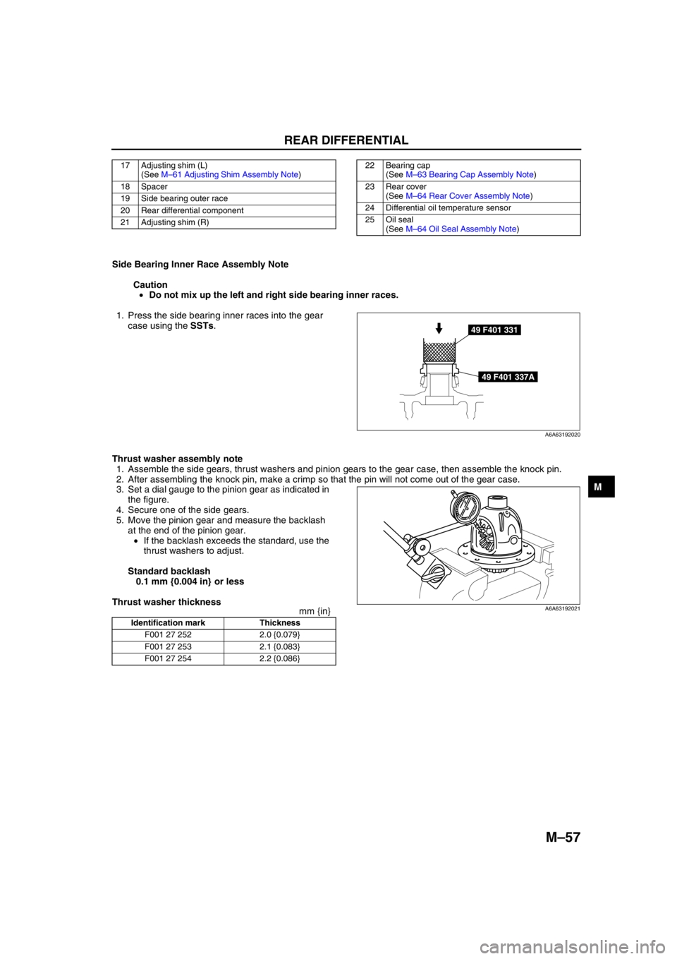
Side Bearing Inner Race Assembly Note
Caution
•Do not mix up the left and right side bearing inner races.
1. Press the side bearing inner races into the gear
case using the SSTs.
Thrust washer assembly note
1. Assemble the side gears, thrust washers and pinion gears to the gear case, then assemble the knock pin.
2. After assembling the knock pin, make a crimp so that the pin will not come out of the gear case.
3. Set a dial gauge to the pinion gear as indicated in
the figure.
4. Secure one of the side gears.
5. Move the pinion gear and measure the backlash
at the end of the pinion gear.
•If the backlash exceeds the standard, use the
thrust washers to adjust.
Standard backlash
0.1 mm {0.004 in} or less
Thrust washer thickness
mm {in}
17 Adjusting shim (L)
(See M–61 Adjusting Shim Assembly Note)
18 Spacer
19 Side bearing outer race
20 Rear differential component
21 Adjusting shim (R)22 Bearing cap
(See M–63 Bearing Cap Assembly Note)
23 Rear cover
(See M–64 Rear Cover Assembly Note)
24 Differential oil temperature sensor
25 Oil seal
(See M–64 Oil Seal Assembly Note)
49 F401 331
49 F401 337A
A6A63192020
Identification mark Thickness
F001 27 252 2.0 {0.079}
F001 27 253 2.1 {0.083}
F001 27 254 2.2 {0.086}
A6A63192021
Page 692 of 909
M–62
REAR DIFFERENTIAL
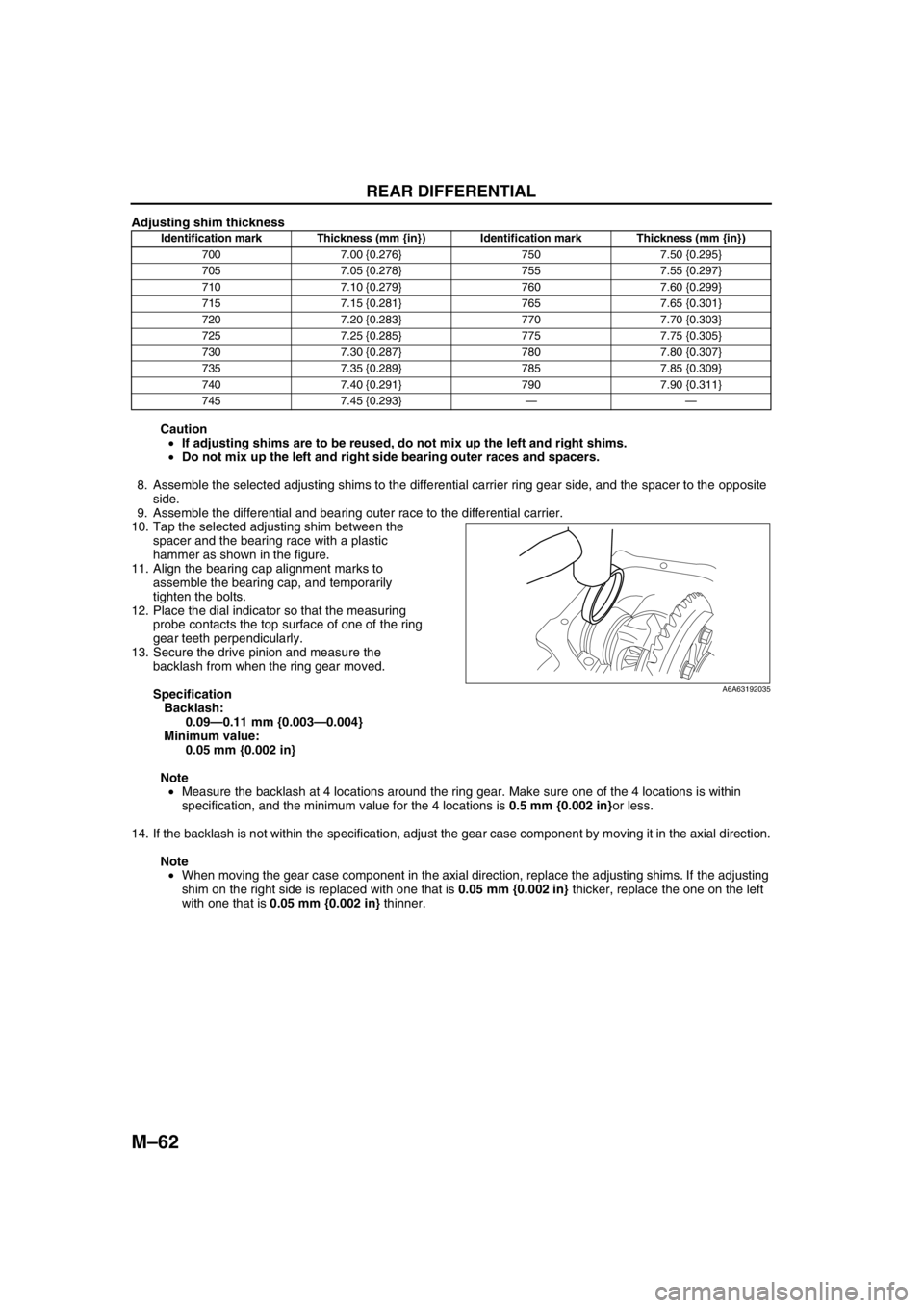
Adjusting shim thickness
Caution
•If adjusting shims are to be reused, do not mix up the left and right shims.
•Do not mix up the left and right side bearing outer races and spacers.
8. Assemble the selected adjusting shims to the differential carrier ring gear side, and the spacer to the opposite
side.
9. Assemble the differential and bearing outer race to the differential carrier.
10. Tap the selected adjusting shim between the
spacer and the bearing race with a plastic
hammer as shown in the figure.
11. Align the bearing cap alignment marks to
assemble the bearing cap, and temporarily
tighten the bolts.
12. Place the dial indicator so that the measuring
probe contacts the top surface of one of the ring
gear teeth perpendicularly.
13. Secure the drive pinion and measure the
backlash from when the ring gear moved.
Specification
Backlash:
0.09—0.11 mm {0.003—0.004}
Minimum value:
0.05 mm {0.002 in}
Note
•Measure the backlash at 4 locations around the ring gear. Make sure one of the 4 locations is within
specification, and the minimum value for the 4 locations is 0.5 mm {0.002 in}or less.
14. If the backlash is not within the specification, adjust the gear case component by moving it in the axial direction.
Note
•When moving the gear case component in the axial direction, replace the adjusting shims. If the adjusting
shim on the right side is replaced with one that is 0.05 mm {0.002 in} thicker, replace the one on the left
with one that is 0.05 mm {0.002 in} thinner.
Identification mark Thickness (mm {in}) Identification mark Thickness (mm {in})
700 7.00 {0.276} 750 7.50 {0.295}
705 7.05 {0.278} 755 7.55 {0.297}
710 7.10 {0.279} 760 7.60 {0.299}
715 7.15 {0.281} 765 7.65 {0.301}
720 7.20 {0.283} 770 7.70 {0.303}
725 7.25 {0.285} 775 7.75 {0.305}
730 7.30 {0.287} 780 7.80 {0.307}
735 7.35 {0.289} 785 7.85 {0.309}
740 7.40 {0.291} 790 7.90 {0.311}
745 7.45 {0.293}——
A6A63192035
Page 700 of 909
M–70
ELECTRONIC 4WD CONTROL SYSTEM
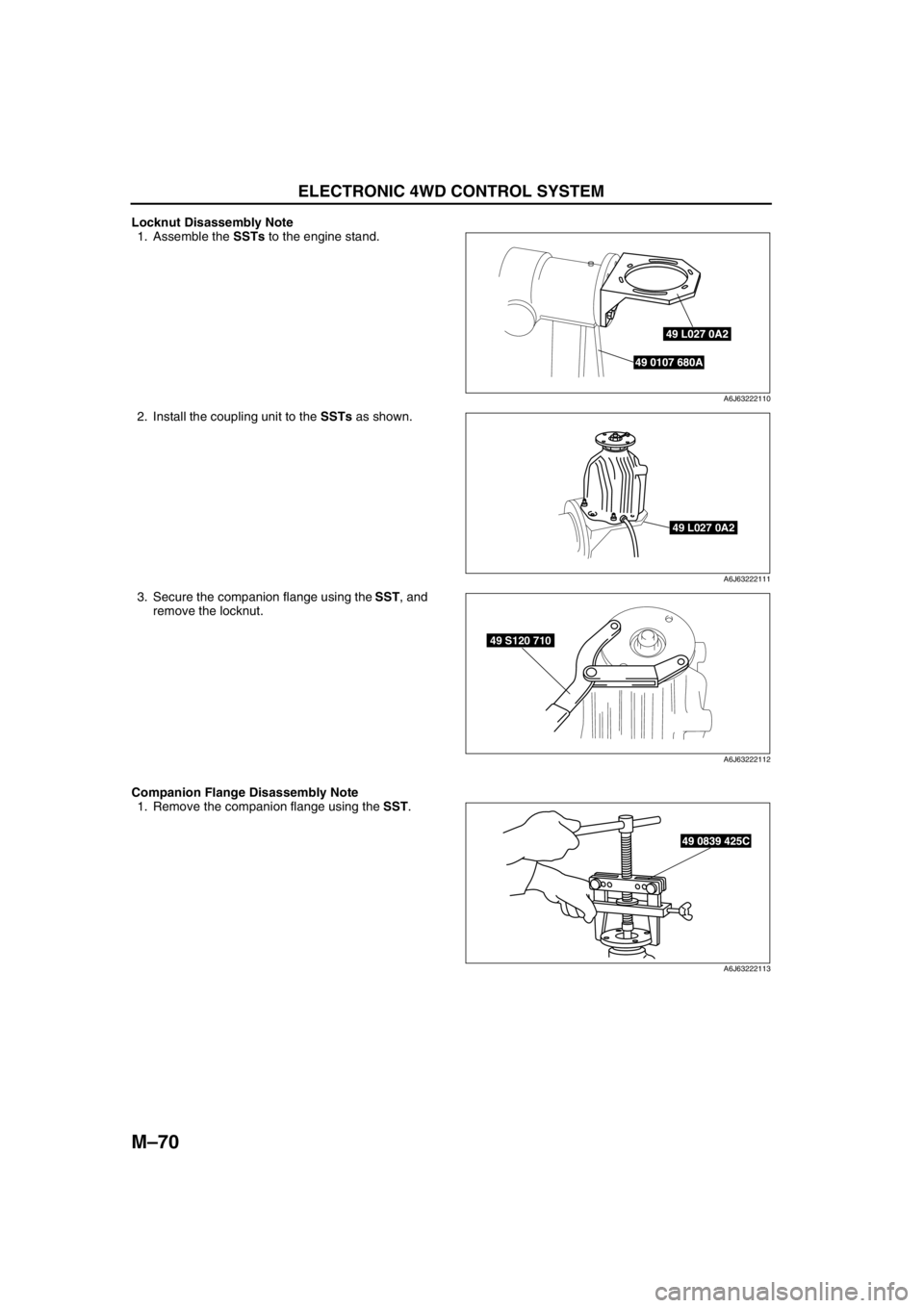
Locknut Disassembly Note
1. Assemble the SSTs to the engine stand.
2. Install the coupling unit to the SSTs as shown.
3. Secure the companion flange using the SST, and
remove the locknut.
Companion Flange Disassembly Note
1. Remove the companion flange using the SST.
49 L027 0A2
49 0107 680A
A6J63222110
49 L027 0A2
A6J63222111
49 S120 710
A6J63222112
49 0839 425C
A6J63222113
Page 701 of 909
ELECTRONIC 4WD CONTROL SYSTEM
M–71
M
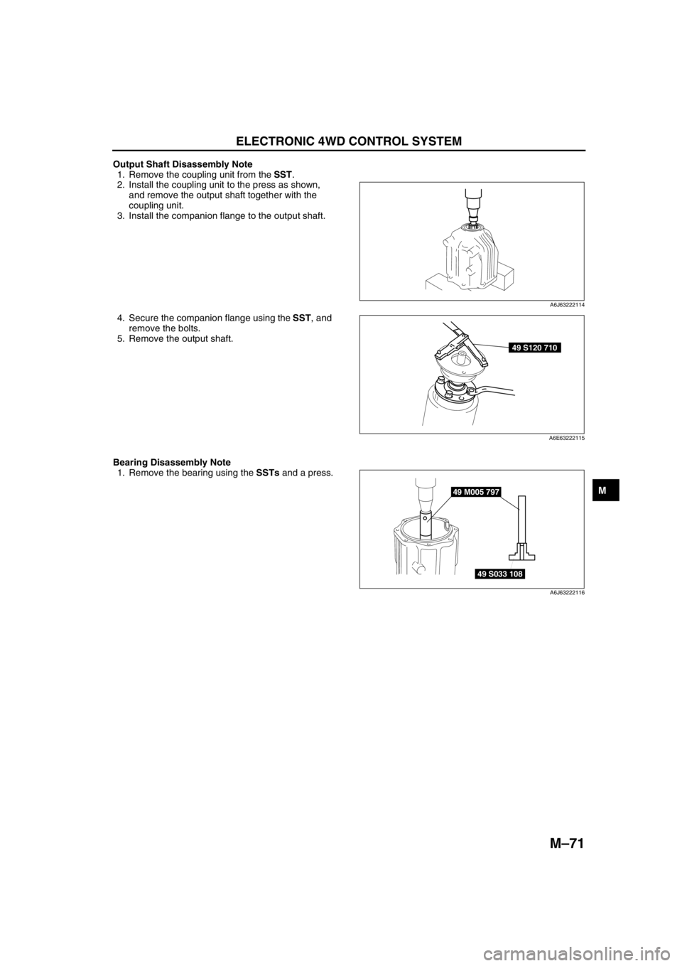
Output Shaft Disassembly Note
1. Remove the coupling unit from the SST.
2. Install the coupling unit to the press as shown,
and remove the output shaft together with the
coupling unit.
3. Install the companion flange to the output shaft.
4. Secure the companion flange using the SST, and
remove the bolts.
5. Remove the output shaft.
Bearing Disassembly Note
1. Remove the bearing using the SSTs and a press.
End Of Sie
A6J63222114
49 S120 710
A6E63222115
49 M005 797
49 S033 108
A6J63222116
Page 703 of 909
ELECTRONIC 4WD CONTROL SYSTEM
M–73
M
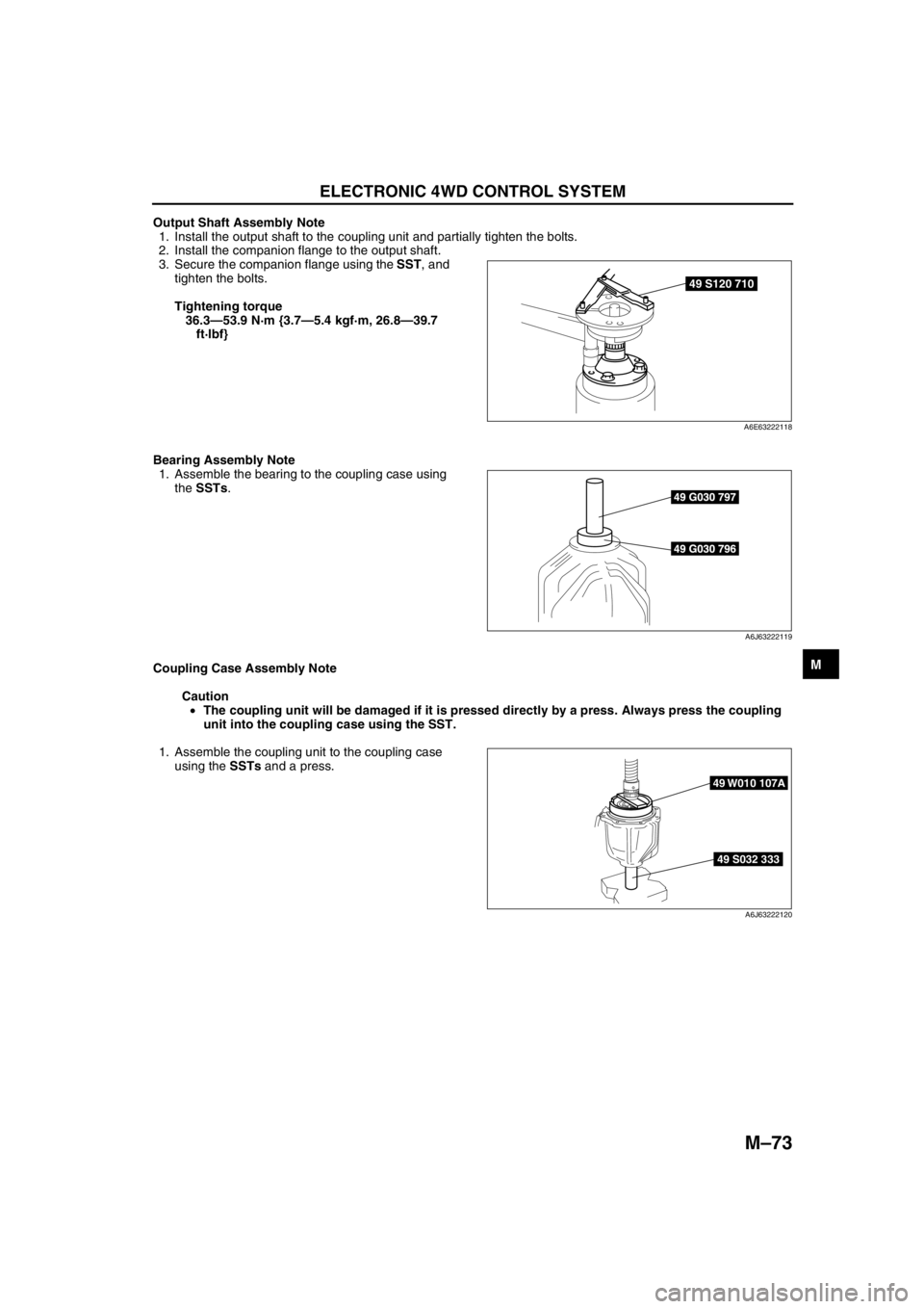
Output Shaft Assembly Note
1. Install the output shaft to the coupling unit and partially tighten the bolts.
2. Install the companion flange to the output shaft.
3. Secure the companion flange using the SST, and
tighten the bolts.
Tightening torque
36.3—53.9 N·m {3.7—5.4 kgf·m, 26.8—39.7
ft·lbf}
Bearing Assembly Note
1. Assemble the bearing to the coupling case using
the SSTs.
Coupling Case Assembly Note
Caution
•The coupling unit will be damaged if it is pressed directly by a press. Always press the coupling
unit into the coupling case using the SST.
1. Assemble the coupling unit to the coupling case
using the SSTs and a press.
49 S120 710
A6E63222118
49 G030 797
49 G030 796
A6J63222119
49 S032 333
49 W010 107A
A6J63222120
Page 704 of 909
M–74
ELECTRONIC 4WD CONTROL SYSTEM
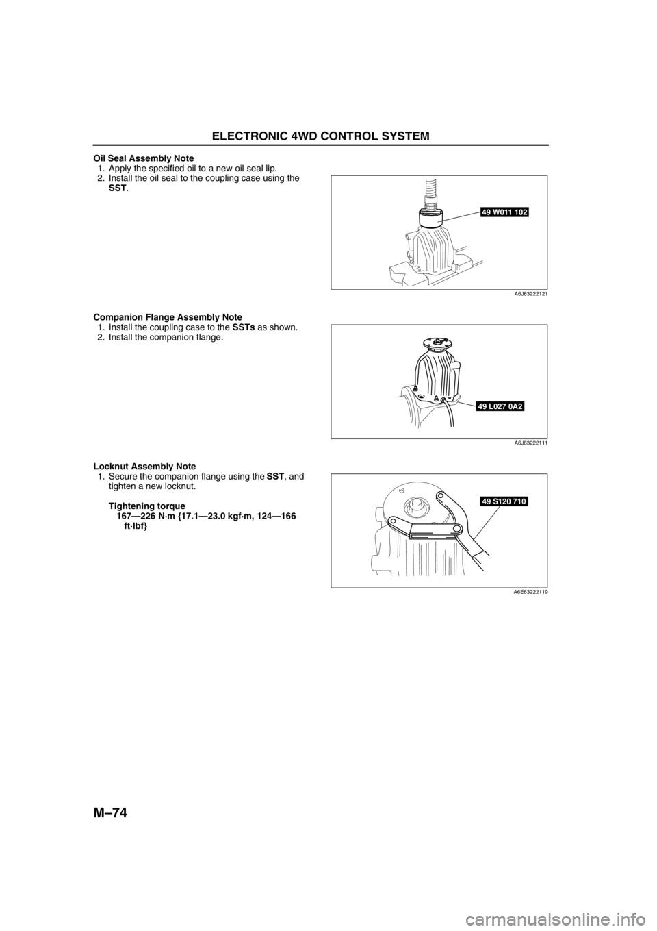
Oil Seal Assembly Note
1. Apply the specified oil to a new oil seal lip.
2. Install the oil seal to the coupling case using the
SST.
Companion Flange Assembly Note
1. Install the coupling case to the SSTs as shown.
2. Install the companion flange.
Locknut Assembly Note
1. Secure the companion flange using the SST, and
tighten a new locknut.
Tightening torque
167—226 N·m {17.1—23.0 kgf·m, 124—166
ft·lbf}
End Of Sie
49 W011 102
A6J63222121
49 L027 0A2
A6J63222111
49 S120 710
A6E63222119
Page 713 of 909
TROUBLESHOOTING
M–83
M
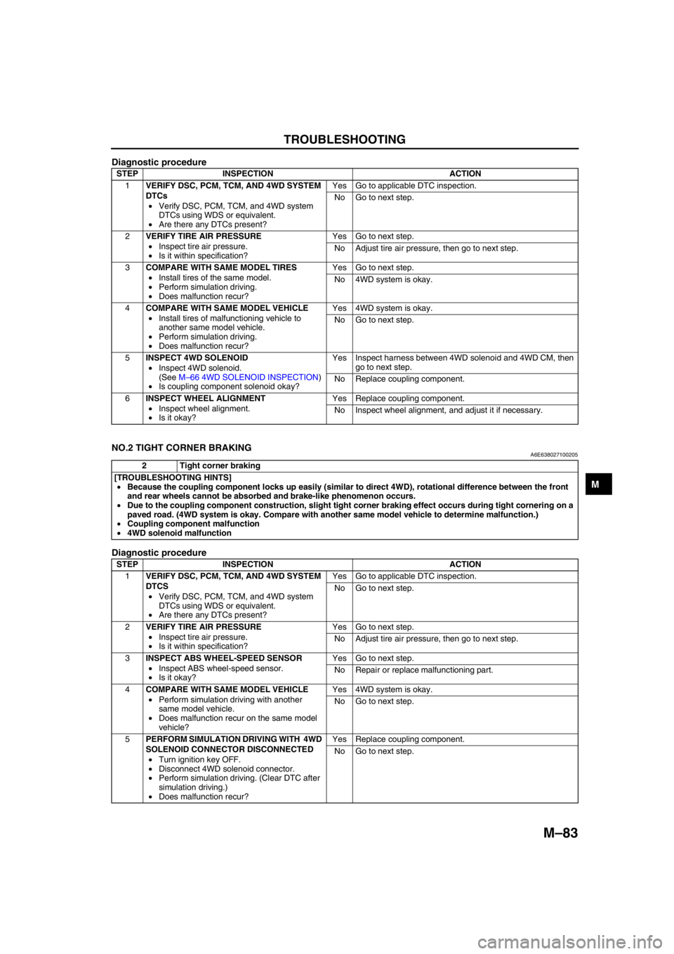
Diagnostic procedure
End Of Sie
NO.2 TIGHT CORNER BRAKINGA6E638027100205
Diagnostic procedure
STEP INSPECTION ACTION
1VERIFY DSC, PCM, TCM, AND 4WD SYSTEM
DTCs
•Verify DSC, PCM, TCM, and 4WD system
DTCs using WDS or equivalent.
•Are there any DTCs present?Yes Go to applicable DTC inspection.
No Go to next step.
2VERIFY TIRE AIR PRESSURE
•Inspect tire air pressure.
•Is it within specification?Yes Go to next step.
No Adjust tire air pressure, then go to next step.
3COMPARE WITH SAME MODEL TIRES
•Install tires of the same model.
•Perform simulation driving.
•Does malfunction recur?Yes Go to next step.
No 4WD system is okay.
4COMPARE WITH SAME MODEL VEHICLE
•Install tires of malfunctioning vehicle to
another same model vehicle.
•Perform simulation driving.
•Does malfunction recur?Yes 4WD system is okay.
No Go to next step.
5INSPECT 4WD SOLENOID
•Inspect 4WD solenoid.
(See M–66 4WD SOLENOID INSPECTION)
•Is coupling component solenoid okay?Yes Inspect harness between 4WD solenoid and 4WD CM, then
go to next step.
No Replace coupling component.
6INSPECT WHEEL ALIGNMENT
•Inspect wheel alignment.
•Is it okay?Yes Replace coupling component.
No Inspect wheel alignment, and adjust it if necessary.
2 Tight corner braking
[TROUBLESHOOTING HINTS]
•Because the coupling component locks up easily (similar to direct 4WD), rotational difference between the front
and rear wheels cannot be absorbed and brake-like phenomenon occurs.
•Due to the coupling component construction, slight tight corner braking effect occurs during tight cornering on a
paved road. (4WD system is okay. Compare with another same model vehicle to determine malfunction.)
•Coupling component malfunction
•4WD solenoid malfunction
STEP INSPECTION ACTION
1VERIFY DSC, PCM, TCM, AND 4WD SYSTEM
DTCS
•Verify DSC, PCM, TCM, and 4WD system
DTCs using WDS or equivalent.
•Are there any DTCs present?Yes Go to applicable DTC inspection.
No Go to next step.
2VERIFY TIRE AIR PRESSURE
•Inspect tire air pressure.
•Is it within specification?Yes Go to next step.
No Adjust tire air pressure, then go to next step.
3INSPECT ABS WHEEL-SPEED SENSOR
•Inspect ABS wheel-speed sensor.
•Is it okay?Yes Go to next step.
No Repair or replace malfunctioning part.
4COMPARE WITH SAME MODEL VEHICLE
•Perform simulation driving with another
same model vehicle.
•Does malfunction recur on the same model
vehicle?Yes 4WD system is okay.
No Go to next step.
5PERFORM SIMULATION DRIVING WITH 4WD
SOLENOID CONNECTOR DISCONNECTED
•Turn ignition key OFF.
•Disconnect 4WD solenoid connector.
•Perform simulation driving. (Clear DTC after
simulation driving.)
•Does malfunction recur?Yes Replace coupling component.
No Go to next step.
Page 725 of 909
ENGINE SPEED SENSING POWER STEERING
N–11
N
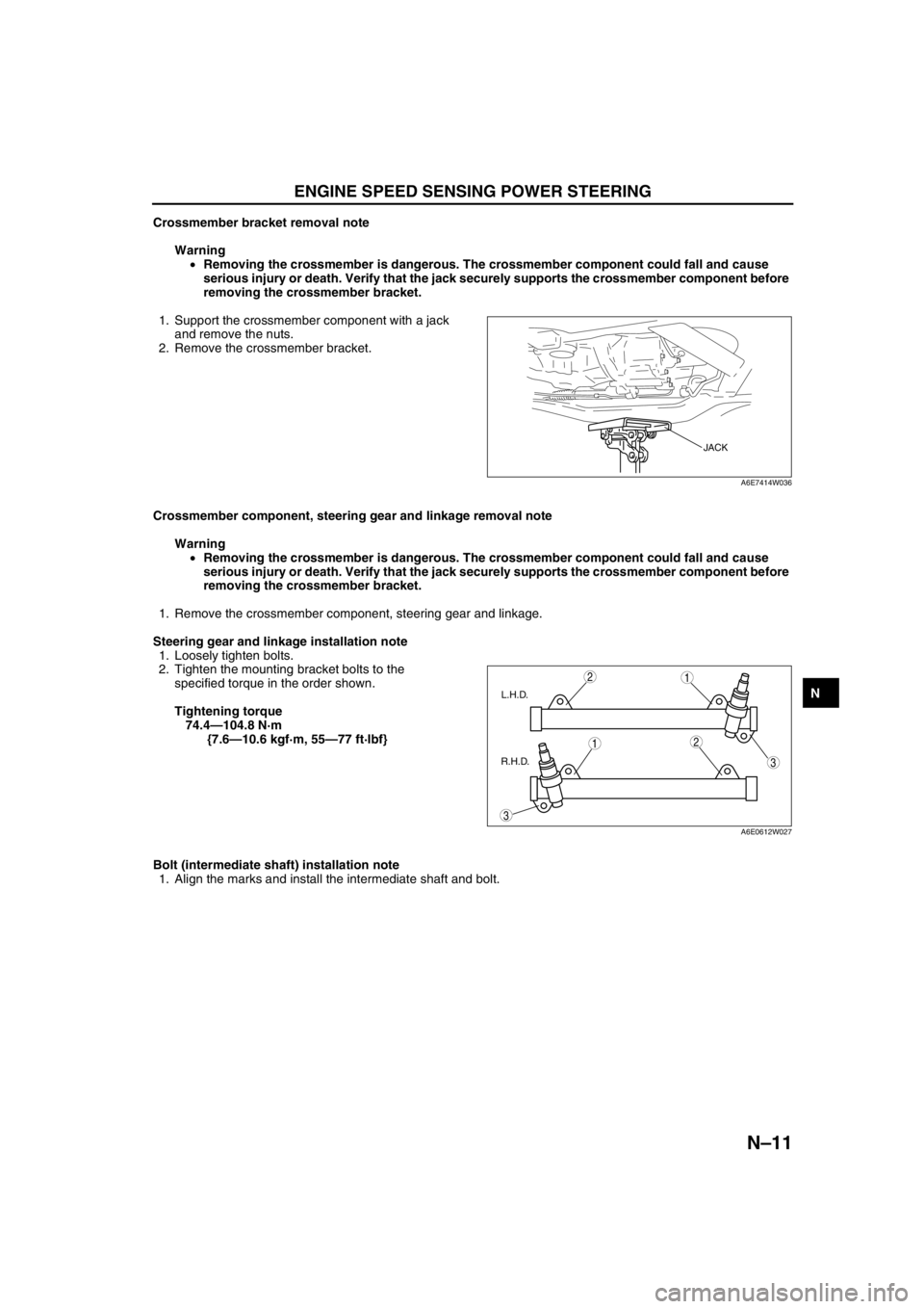
Crossmember bracket removal note
Warning
•Removing the crossmember is dangerous. The crossmember component could fall and cause
serious injury or death. Verify that the jack securely supports the crossmember component before
removing the crossmember bracket.
1. Support the crossmember component with a jack
and remove the nuts.
2. Remove the crossmember bracket.
Crossmember component, steering gear and linkage removal note
Warning
•Removing the crossmember is dangerous. The crossmember component could fall and cause
serious injury or death. Verify that the jack securely supports the crossmember component before
removing the crossmember bracket.
1. Remove the crossmember component, steering gear and linkage.
Steering gear and linkage installation note
1. Loosely tighten bolts.
2. Tighten the mounting bracket bolts to the
specified torque in the order shown.
Tightening torque
74.4—104.8 N·m
{7.6—10.6 kgf·m, 55—77 ft·lbf}
Bolt (intermediate shaft) installation note
1. Align the marks and install the intermediate shaft and bolt.
JACK
A6E7414W036
3
3
1
1
2
2
L.H.D.
R.H.D.
A6E0612W027