ECU MAZDA 6 2002 Suplement Repair Manual
[x] Cancel search | Manufacturer: MAZDA, Model Year: 2002, Model line: 6, Model: MAZDA 6 2002Pages: 909, PDF Size: 17.16 MB
Page 732 of 909

N–18
ENGINE SPEED SENSING POWER STEERING
Power Steering Oil Pump Component Disassembly Note
1. Secure the power pressure oil pump using the SST.
Caution
•Use the SST to prevent damage to the
pump when securing it in a vise.
Clip Disassembly Note
1. Lift up the clip tab using a flathead screwdriver.
2. Remove the clip by pushing it with a flathead
screwdriver and a hammer as shown in the figure.
Vane Assembly Note
1. Place the vanes in the rotor with the rounded
edges contacting the cam.
10 Rear pump body
(See N–19 Rear Pump Body Assembly Note)
11 Gasket
12 Cam ring
(See N–19 Cam Ring Assembly Note)13 Rotor
14 Vane
(See N–18 Vane Assembly Note)
15 Side plate
16 Power steering oil pump
49 F032 301
A6E66142010
CLIP
R
A6E66142008
A6E6316W013
Page 733 of 909

ENGINE SPEED SENSING POWER STEERING
N–19
N
Cam Ring Assembly Note
1. Install the cam ring in the front pump body with
the mark facing upward.
Rear Pump Body Assembly Note
1. After installing the rear body, manually turn the shaft to verify that it rotates smoothly.
Clip Assembly Note
1. Push the clip slowly in the direction shown in the
figure.
2. Confirm that the clip tab is securely fastened.
End Of Sie
A6E6316W014
CLIP
R
A6E66142009
Page 778 of 909

R–16
REAR SUSPENSION
Bolt (Trailing Link Front Side) Removal Note
1. Support the trailing link with a jack.
Caution
•Removing the trailing link is dangerous.
The trailing link could fall and cause
serious injury or death. Verify that the
jack securely supports the trailing link.
2. Remove the bolts (trailing link front side).
Bolt (Lateral Link Outer Side) Removal Note
1. Loosen the bolt (lateral link inner side).
2. Remove the bolt (lateral link outer side).
Bolt (Lateral Link Outer Side) Installation Note
1. Tighten the bolt (lateral link outer side).
2. Tighten the bolt (lateral link inner side).
Tightening torque
86.2—116.6 N·m {8.80—11.88 kgf·m, 63.58—85.99 ft·lbf}
Bolt (Trailing Link Front Side) Installation Note
1. Support the trailing link with a jack.
2. Tighten the bolts (trailing link front side).
End Of SieREAR CROSSMEMBER REMOVAL/INSTALLATION (4WD)A6E741628400201
Caution
•Performing the following procedures without first removing the ABS wheel-speed sensor may
possibly cause an open circuit in the harness if it is pulled by mistake. Before performing the
following procedures, remove the ABS wheel-speed sensor (axle side) and fix it to an appropriate
place where the sensor will not be pulled by mistake while servicing the vehicle.
1. Remove the rear auto leveling sensor and harness.
(See T–20 REAR AUTO LEVELING SENSOR REMOVAL/INSTALLATION.)
2. Remove the middle pipe.
(See F1–30 EXHAUST SYSTEM REMOVAL/INSTALLATION.)
3. Remove in the order indicated in the table.
4. Install in the reverse order of removal.
5. Adjust the headlight zeroset.
6. Inspect the rear wheel alignment.
(See R–9 REAR WHEEL ALIGNMENT (WGN).)
JACK
A6E74162010
JACK
A6E74162010
Page 780 of 909

R–18
REAR SUSPENSION
Crossmember component, Differential And Drive Shaft Removal Note
1. Support the differential with a jack, and remove
the nut.
Warning
•Removing the crossmember component,
differential and drive shaft is dangerous.
The crossmember component,
differential and drive shaft could fall and
cause serious injury or death. Verify that
the jack securely supports the differential
lower side.
2. Remove the crossmember component,
differential and drive shaft.
Rear Crossmember Bushing Removal Note
1. Remove the bushing using a screw driver (-),
being careful not to damage the rear
crossmember.
Rear Crossmember Bushing Installation Note
1. Set the bushings as shown in the figure.
JACK
A6E74162012
A6E7416W001
A
B
D
C
A
B
C,D
FRONT
UPPER SIDELOWER SIDE
OVAL
HOLECROSS-
SECTIONAL
VIEW
A6E74162014
Page 793 of 909

S–12
MOLDING
ROOF MOLDING REMOVALA6E773050620201With Roof Rail
1. Remove the roof rail.
2. Detach the clips which secure A section of roof
moldings, using a screwdriver or equivalent tool.
3. Remove the roof molding No.2 and No.3.
4. While pulling the roof molding No.1 up, detach the
fit for the T stud of the B section and the roof
molding No.1 and then remove the roof molding
No.1.
End Of Sie
ROOF MOLDING INSTALLATIONA6E773050620202With Roof Rail
1. Attach the roof molding No.1 to the T stud at the A
section.
2. Hook the roof molding No.1 to clip B at the B
section, press it in, and attach the roof molding
No.1 to clip B.
MOLDING
FRONTb
ba
a B
TOP VIEW
SEC. a—a CLIP
SEC. b—b T STUD
ROOF
MOLDING No.3RROOF
MOLDING No.1R
ROOF
MOLDING No.2R
AAA
AA A
A6A7730W102
FRONTb
b a
aB
A
TOP VIEW
SEC. a—a T STUD
ROOF MOLDING No.1
SEC. b—b CLIP B
A6A7730W104
Page 813 of 909

T–2
OUTLINE, POWER SYSTEM
OUTLINE OF CONSTRUCTIONA6E810201088201•The construction and operation of the body electrical system is essentially carried over from that of the current
Mazda6 (GG) model, except for the following features. (See Mazda6 Training Manual 3359-1*-02C)
End Of Sie
FEATURESA6E810201088202Improved Safety
•There are two types of high-mount brake lights. (WGN)
Improved Marketability
•A cargo compartment light has been adopted. (WGN)
•The installation positions of the rear wiper and washer components have been changed. (WGN)
•A fuel gauge sender sub-unit has been adopted. (4WD)
•A 4WD indicator light, glow indicator light and sedimentor warning light have been adopted.
•The installation positions of the condenser and the noise filter have been changed. (WGN)
•An antenna feeder has been adopted. (WGN)
•A rear auto leveling sensor especially for the 4WD has been adopted. (4WD)
Improved Security
•A rear intruder sensor has been adopted. (WGN)
End Of Sie
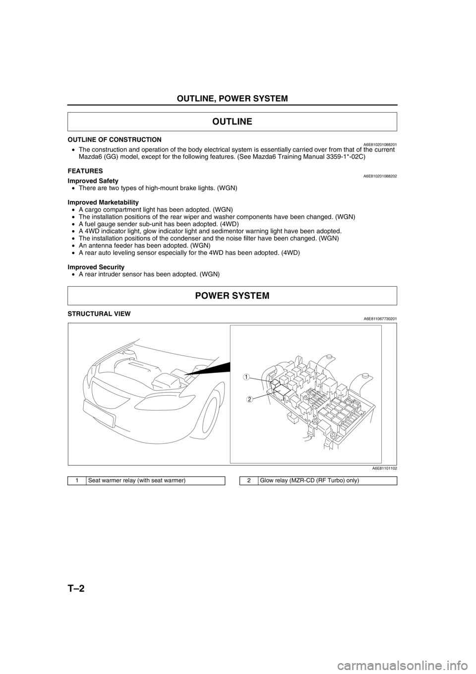
STRUCTURAL VIEWA6E811067730201
.
End Of Sie
OUTLINE
POWER SYSTEM
2
1
A6E81101102
1 Seat warmer relay (with seat warmer)2 Glow relay (MZR-CD (RF Turbo) only)
Page 848 of 909

AIR BAG SYSTEM
T–37
T
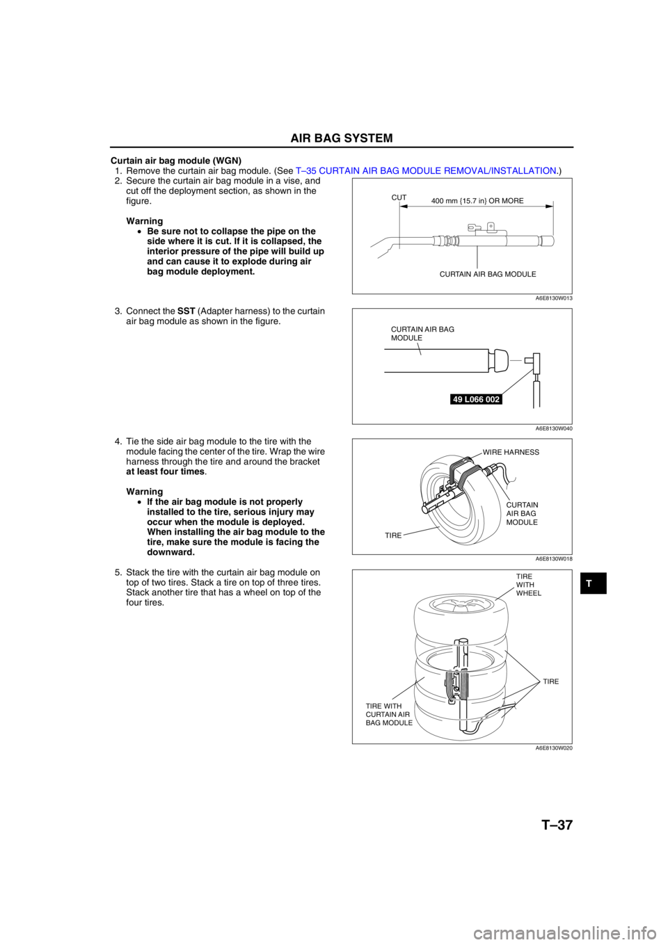
Curtain air bag module (WGN)
1. Remove the curtain air bag module. (See T–35 CURTAIN AIR BAG MODULE REMOVAL/INSTALLATION.)
2. Secure the curtain air bag module in a vise, and
cut off the deployment section, as shown in the
figure.
Warning
•Be sure not to collapse the pipe on the
side where it is cut. If it is collapsed, the
interior pressure of the pipe will build up
and can cause it to explode during air
bag module deployment.
3. Connect the SST (Adapter harness) to the curtain
air bag module as shown in the figure.
4. Tie the side air bag module to the tire with the
module facing the center of the tire. Wrap the wire
harness through the tire and around the bracket
at least four times.
Warning
•If the air bag module is not properly
installed to the tire, serious injury may
occur when the module is deployed.
When installing the air bag module to the
tire, make sure the module is facing the
downward.
5. Stack the tire with the curtain air bag module on
top of two tires. Stack a tire on top of three tires.
Stack another tire that has a wheel on top of the
four tires.
CUT
CURTAIN AIR BAG MODULE400 mm {15.7 in} OR MORE
A6E8130W013
49 L066 002
CURTAIN AIR BAG
MODULE
A6E8130W040
WIRE HARNESS
CURTAIN
AIR BAG
MODULE
TIRE
A6E8130W018
TIRE
WITH
WHEEL
TIRE WITH
CURTAIN AIR
BAG MODULETIRE
A6E8130W020