ECU MAZDA 6 2002 Suplement Owner's Manual
[x] Cancel search | Manufacturer: MAZDA, Model Year: 2002, Model line: 6, Model: MAZDA 6 2002Pages: 909, PDF Size: 17.16 MB
Page 326 of 909

F2–174
TROUBLESHOOTING
NO.2 MIL ILLUMINATESA6E408018881204
Diagnostic procedure
End Of Sie
NO.3 WILL NOT CRANKA6E408018881205
Diagnostic procedure
2 MIL ILLUMINATES
DESCRIPTION•MIL illuminates incorrectly.
POSSIBLE
CAUSE•PCM illuminates for emission-related concern (DTC is stored in PCM)
•Instrument cluster malfunction
Note
•If MIL blinks at steady rate, misfire condition could possibly exist.
STEP INSPECTION RESULTS ACTION
1 Connect WDS or equivalent to DLC-2.
Turn engine switch to ON.
Retrieve any DTC.
Is DTC displayed?YesDTC is displayed:
•Go to appropriate DTC test.
NoNo DTC is displayed:
•Inspect instrument cluster operation.
2 Verify test results.
•If okay, return to diagnostic index to service any additional symptoms.
•If malfunction remains, replace PCM. (See F2–64 PCM REMOVAL/INSTALLATION)
3 WILL NOT CRANK
DESCRIPTION•Starter does not work.
POSSIBLE
CAUSE•Open starter circuit between engine switch and starter
•Starter malfunction
•Seized/hydrolocked engine, flywheel
•Immobilizer system (PATS) and/or circuit malfunction (if equipped)
•Low or dead battery
•Charging system malfunction
STEP INSPECTION RESULTS ACTION
1Note
•The following test should be perform for
vehicles with immobilizer system. Go to
Step 10 for vehicles without immobilizer
system.
Connect WDS or equivalent to DLC-2.
Do following conditions appear?
•Engine is not completely started.
•DTC B1681 is displayed.YesBoth conditions appear:
Go to Step 4.
NoEither or other condition appears:
Go to next step.
2 Is coil connector securely connected to coil? Yes Go to next step.
No Connect coil connector securely.
Return to Step 1.
3 Does security light illuminate? Yes Go to next step.
No Inspect instrument cluster and wiring harness.
4 Connect WDS or equivalent to DLC-2 and
retrieve DTC.
DTC
B1213, B1342, B1600, B1601, B1602, B1681,
B2103, B2431Yes Go to appropriate DTC test.
No Go to next step.
Page 330 of 909

F2–178
TROUBLESHOOTING
End Of Sie
NO.5 ENGINE STALLS-AFTER START/AT IDLEA6E408018881207
Diagnostic Procedure
18 Verify test results.
•If okay, return to diagnostic index to service any additional symptoms.
•If malfunction remains, replace PCM. (See F2–64 PCM REMOVAL/INSTALLATION) STEP INSPECTION RESULTS ACTION
5 ENGINE STALLS-AFTER START/AT IDLE
DESCRIPTION•Engine stops unexpectedly.
POSSIBLE
CAUSE•Poor fuel quality
•Intake-air system restriction or clogging
•Engine overheating
•A/C system improper operation
•Immobilizer system (PATS) and/or circuit malfunction (if equipped)
•PCM control relay malfunction
•Glow system malfunction
•Inadequate fuel pressure
•Fuel pressure sensor related circuit malfunction
•Suction control valve malfunction (built-in supply pump)
•Fuel pressure limiter malfunction (built-in common rail)
•Fuel leakage
•Fuel line clogging or restriction
•Fuel filter clogging or restriction
•Incorrect fuel injection timing
•Erratic signal from CKP sensor
•Erratic signal from CMP sensor
•Supply pump malfunction
•Fuel injector malfunction
•Low engine compression
•Improper valve timing
•Exhaust system and/or catalyst converter restriction or clogging
•EGR system malfunction
•ECT sensor or related circuit malfunction
•Accelerator positions sensor or related circuit malfunction
•Accelerator positions sensor misadjustment
•MAF/IAT sensor or related circuit malfunction
•V-reference voltage supply circuit malfunction
•IDM or related circuit malfunction
Warning
The following troubleshooting flow chart contains the fuel system diagnosis and repair
procedures. Read the following warnings before performing the fuel system services:
•Fuel vapor is hazardous. It can easily ignite, causing serious injury and damage. Always keep
sparks and flames away from fuel.
•Fuel line spills and leakage are dangerous. Fuel can ignite and cause serious injury or death
and damage. Fuel can also irritate skin and eyes. To prevent this, always complete “BEFORE
REPAIR PROCEDURE” and “AFTER REPAIR PROCEDURE” described in this manual.
STEP INSPECTION RESULTS ACTION
1Note
•The following test should be perform for
vehicles with immobilizer system. Go to
Step 10 for vehicles without immobilizer
system.
Connect WDS or equivalent to DLC-2.
Do following conditions appear?
•Engine is not completely started.
•DTC B1681 is displayed.YesBoth conditions appear:
Go to Step 4.
NoEither or other condition appears:
Go to next step.
2 Is coil connector securely connected to coil? Yes Go to next step.
No Connect coil connector securely.
Return to Step 1.
3 Does security light illuminate? Yes Go to next step.
No Inspect instrument cluster and wiring harness.
Page 333 of 909

TROUBLESHOOTING
F2–181
F2
End Of Sie
NO.6 CRANKS NORMALLY BUT WILL NOT STARTA6E408018881208
Diagnostic Procedure
28 Inspect IDM.
(See F2–84 INJECTOR DRIVER MODULE
(IDM) INSPECTION)
Is IDM okay?Yes Go to next step.
No Repair or replace as necessary.
29 Inspect EGR system operation.
Is EGR system operation normal?Yes Remove and inspect supply pump and common rail.
No Repair or replace malfunctioning part according to
EGR system operation results.
30 Verify test results.
•If okay, return to diagnostic index to service any additional symptoms.
•If malfunction remains, replace PCM. (See F2–64 PCM REMOVAL/INSTALLATION) STEP INSPECTION RESULTS ACTION
6 CRANKS NORMALLY BUT WILL NOT START
DESCRIPTION•Starter cranks engine at normal speed but engine will not run.
•Refer to symptom troubleshooting “No.5 Engine stalls” if this symptom appears after engine stall.
•Fuel is in fuel tank.
•Battery is in normal condition.
POSSIBLE
CAUSE•Poor fuel quality
•Intake-air system restriction
•Fuel line restriction
•EGR system malfunction
•Glow system malfunction
•Fuel pressure sensor or related circuit malfunction
•Suction control valve malfunction (built-in supply pump)
•Fuel pressure limiter malfunction (built-in common rail)
•Fuel leakage
•Fuel filter clogging
•Incorrect fuel injection timing
•Erratic signal from CKP sensor
•Erratic signal from CMP sensor
•V-reference supply circuit malfunction
•ECT sensor or related circuit malfunction
•Supply pump malfunction
•Fuel injector malfunction
•Immobilizer system (PATS) and/or circuit malfunction (if equipped)
•Low engine compression
•Improper valve timing
•IDM or related circuit malfunction
•PCM control repay malfunction
Warning
The following troubleshooting flow chart contains the fuel system diagnosis and repair
procedures. Read the following warnings before performing the fuel system services:
•Fuel vapor is hazardous. It can easily ignite, causing serious injury and damage. Always keep
sparks and flames away from fuel.
•Fuel line spills and leakage are dangerous. Fuel can ignite and cause serious injury or death
and damage. Fuel can also irritate skin and eyes. To prevent this, always complete “BEFORE
REPAIR PROCEDURE” and “AFTER REPAIR PROCEDURE” described in this manual.
STEP INSPECTION RESULTS ACTION
1Note
•The following test should be perform for
vehicles with immobilizer system. Go to
Step 10 for vehicles without immobilizer
system.
Connect WDS or equivalent to DLC-2.
Do following conditions appear?
•Engine is not completely started.
•DTC B1681 is displayed.YesBoth conditions appear:
Go to Step 4.
NoEither or other condition appears:
Go to next step.
2 Is coil connector securely connected to coil? Yes Go to next step.
No Connect coil connector securely.
Return to Step 1.
Page 334 of 909

F2–182
TROUBLESHOOTING
3 Does security light illuminate? Yes Go to next step.
No Inspect instrument cluster and wiring harness.
4 Connect WDS or equivalent to DLC-2 and
retrieve DTC.
DTC
B1213, B1342, B1600, B1601, B1602, B1681,
B2103, B2431Yes Go to appropriate DTC test.
No Go to next step.
5 Is there continuity between PCM GND terminals
65, 85, 103, 104 and GND?Yes Go to next step.
No Repair or replace wiring harness.
6 Measure voltage between PCM GND terminals
65, 85, 103, 104 and coil terminal C.
Is the voltage below 1.0?Yes Go to next step.
No Repair or replace wiring harness.
7 Turn engine switch to ON.
Access VPWR PID.
Is VPWR PID okay?
Specification
Battery voltageYes Go to next step.
No Repair or replace wiring harness.
8 Disconnect coil connector.
Turn engine switch to ON.
Is there battery voltage at coil connector terminal
D (harness-side)?Yes Inspect for following:
•Open or short circuit between coil terminal A and
PCM terminal 80
•Open or short circuit between coil terminal B and
PCM terminal 28
No Repair or replace wiring harness between coil
connector terminal D and fuse panel.
9 Is there continuity between PCM terminal 57 and
starter relay?Yes Go to next step.
No Repair replace wiring harness.
10 Inspect for following:
•Fuel quality (e.g.: include water
contamination, winter/summer blend)
•Fuel line/fuel filter clogging
•Intake-air system restriction
Are all items okay?Yes Go to next step.
No Service as necessary.
Repeat Step 10.
11Note
•Ignore DTC P0122, P0123, P0222 or
P0223 while performing this test.
Disconnect accelerator position sensor
connector.
Measure voltage at accelerator position sensor
connector VREF terminal (terminal D) with
engine switch ON.
Specification
4.5—5.5 V
Is voltage okay?Yes Go to next step.
No Go to symptom troubleshooting “NO.26 CONSTANT
VOLTAGE”.
12 Connect WDS or equivalent to DLC-2.
Turn engine switch to ON.
Retrieve any DTC.
Is DTC displayed?YesDTC is displayed:
Go to appropriate DTC test.
Communication error message is displayed:
Inspect for following:
•Open circuit between PCM control relay and PCM
terminal 53 or 79
•Open circuit PCM control relay and PCM terminal
69
•PCM control relay stuck open
•Open or poor GND circuit (PCM terminal 65, 85,
103 or 104)
•Poor connection vehicle body GND
NoNo DTC is displayed:
Go to next step. STEP INSPECTION RESULTS ACTION
Page 467 of 909
K2–52
AUTOMATIC TRANSAXLE
Operation
Range determination
•Each range is determined by operating the selector lever, and switching ON/OFF the switch in the TR switch
internal circuit. The present range is detected according to the ON/OFF signal of the switch.
•The following switches are built into the TR switch, and determine each range when the switch is on.
P position switch
R position switch
N position switch
D range switch
End Of Sie
MANUAL MODE SHIFT CONTROL DESCRIPTIONA6E571418901204Outline
Features
•The manual mode shift control is activated by moving the selector lever from the D to M range position (selector
lever is shifted over toward front passenger side).
•Manual mode shift control with a manual shifting system allowing selection of gear positions by manual
operation of the selector lever forward (-) and back (+) has been adopted. Moreover, engine braking for all
gears in manual mode according to the gear ratio is available.
— Shifting between 1GR and 2GR when the vehicle is stopped is possible.
— When shifting from the D to M range while driving, the same gear position is maintained.
— Consecutive shifting in the M range has been adopted. When shifting down from M range 4GR or 3GR, one
gear can be skipped over by rapidly tapping the selector lever two times in the down-shift (-) direction.
•Selector lever position and gear position indicator lights, built into the instrument cluster, have been adopted.
— The selector indicator light includes a selector lever position indicator that displays selector lever positions
and, a gear position indicator light that displays gear positions.
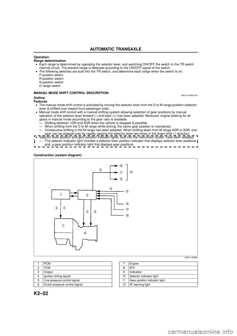
Construction (system diagram)
.
9
8
7
5
43
12
10
18
17
15
16
14
1311
12
6
A6E5714W065
1PCM
2TCM
3Output
4 Ignition timing signal
5 Line pressure control signal
6 Clutch pressure control signal7Engine
8ATX
9 Indication
10 Selector indicator light
11 Gear position indicator light
12 AT warning light
Page 469 of 909
K2–54
AUTOMATIC TRANSAXLE
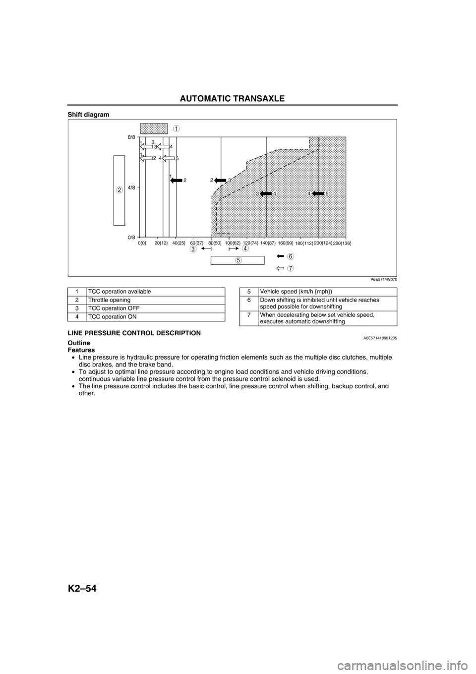
Shift diagram
.
End Of SieLINE PRESSURE CONTROL DESCRIPTIONA6E571418901205Outline
Features
•Line pressure is hydraulic pressure for operating friction elements such as the multiple disc clutches, multiple
disc brakes, and the brake band.
•To adjust to optimal line pressure according to engine load conditions and vehicle driving conditions,
continuous variable line pressure control from the pressure control solenoid is used.
•The line pressure control includes the basic control, line pressure control when shifting, backup control, and
other.
8/8
4/8
0/813
3
1
2 4
4
5 1
2
0{0} 20{12} 40{25} 60{37} 80{50} 100{62} 120{74} 140{87} 160{99}
180{112}200{124}
220{136}
2
3
34 4 5
7
5
43
1
2
6
A6E5714W070
1 TCC operation available
2 Throttle opening
3 TCC operation OFF
4 TCC operation ON5 Vehicle speed (km/h {mph})
6 Down shifting is inhibited until vehicle reaches
speed possible for downshifting
7 When decelerating below set vehicle speed,
executes automatic downshifting
Page 494 of 909
AUTOMATIC TRANSAXLE
K2–79
K2
Automatic Transaxle Fluid (ATF) Level Inspection
Caution
•The ATF amount varies according to ATF's temperature. Therefore, when checking the ATF level or
replacing the ATF, use a thermometer to measure the temperature then adjust the ATF amount to
the specified level according to the specified temperature.
1. Park the vehicle on level ground.
2. Apply the parking brake and position wheel chocks securely to prevent the vehicle from rolling.
3. Adjust the length of the thermistor probe measure to the measure same as the dipstick and hold the probe with
a paper holder.
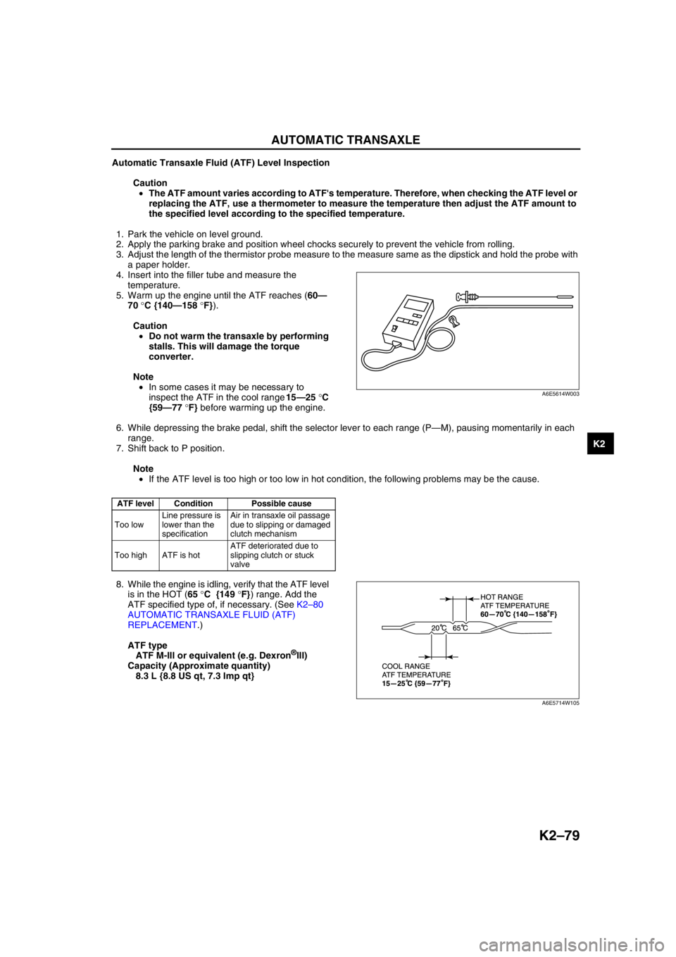
4. Insert into the filler tube and measure the
temperature.
5. Warm up the engine until the ATF reaches (60—
70 °C {140—158 °F}).
Caution
•Do not warm the transaxle by performing
stalls. This will damage the torque
converter.
Note
•In some cases it may be necessary to
inspect the ATF in the cool range 15—25 °C
{59—77 °F} before warming up the engine.
6. While depressing the brake pedal, shift the selector lever to each range (P—M), pausing momentarily in each
range.
7. Shift back to P position.
Note
•If the ATF level is too high or too low in hot condition, the following problems may be the cause.
8. While the engine is idling, verify that the ATF level
is in the HOT (65 °C {149 °F}) range. Add the
ATF specified type of, if necessary. (See K2–80
AUTOMATIC TRANSAXLE FLUID (ATF)
REPLACEMENT.)
ATF type
ATF M-III or equivalent (e.g. Dexron
®III)
Capacity (Approximate quantity)
8.3 L {8.8 US qt, 7.3 Imp qt}
End Of Sie
ATF level Condition Possible cause
Too lowLine pressure is
lower than the
specificationAir in transaxle oil passage
due to slipping or damaged
clutch mechanism
Too high ATF is hotATF deteriorated due to
slipping clutch or stuck
valve
A6E5614W003
A6E5714W105
Page 536 of 909
AUTOMATIC TRANSAXLE SHIFT MECHANISM
K2–121
K2
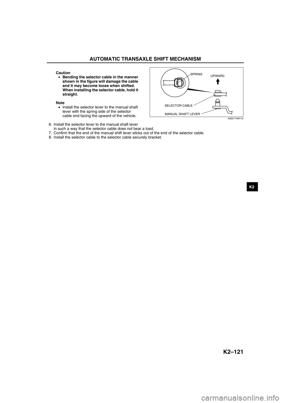
Caution
•Bending the selector cable in the manner
shown in the figure will damage the cable
and it may become loose when shifted.
When installing the selector cable, hold it
straight.
Note
•Install the selector lever to the manual shaft
lever with the spring side of the selector
cable end facing the upward of the vehicle.
6. Install the selector lever to the manual shaft lever
in such a way that the selector cable does not bear a load.
7. Confirm that the end of the manual shift lever sticks out of the end of the selector cable.
8. Install the selector cable to the selector cable securely bracket.
End Of Sie
SELECTOR CABLE
MANUAL SHAFT LEVERSPRING
UPWARD
A6E5714W115
Page 540 of 909

ON-BOARD DIAGNOSTIC
K2–125
K2
•For P0740
i. Start the engine.
ii. Warm up the engine and ATX.
iii. Drive vehicle under the following conditions for 10 seconds or more.
—Vehicle speed (VSS PID): 76 km/h {47 mph}
—Selector lever position: D range
—TCC operating
iv. Go to Step 5.
•For P0743
i. Start the engine.
ii. Warm up the engine and ATX.
iii. Drive the vehicle in D range and make sure that the gears shift smoothly from 1GR to 5GR and TCC is
operated.
iv. Go to Step 5.
•For P0748, P0751, P0752, P0753, P0756, P0757, P0758, P0761, P0762, P0763, P0768, P0773, P0778,
P0798, P1710, PC073, PC100
i. Start the engine.
ii. Warm up the engine and ATX.
iii. Drive the vehicle in D range and make sure that the gears shift smoothly from 1GR to 5GR.
iv. Go to Step 5.
5. Gradually slow down and stop the vehicle.
6. Make sure that the repaired DTC does not recur.
End Of Sie
Page 542 of 909
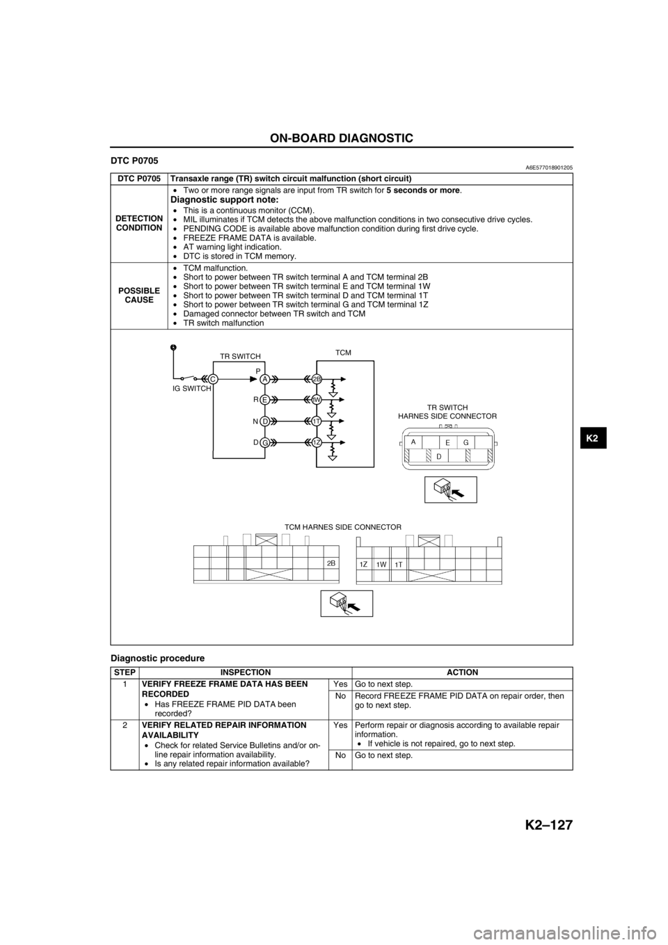
ON-BOARD DIAGNOSTIC
K2–127
K2
DTC P0705A6E577018901205
Diagnostic procedure
DTC P0705 Transaxle range (TR) switch circuit malfunction (short circuit)
DETECTION
CONDITION•Two or more range signals are input from TR switch for 5 seconds or more.
Diagnostic support note:
•This is a continuous monitor (CCM).
•MIL illuminates if TCM detects the above malfunction conditions in two consecutive drive cycles.
•PENDING CODE is available above malfunction condition during first drive cycle.
•FREEZE FRAME DATA is available.
•AT warning light indication.
•DTC is stored in TCM memory.
POSSIBLE
CAUSE•TCM malfunction.
•Short to power between TR switch terminal A and TCM terminal 2B
•Short to power between TR switch terminal E and TCM terminal 1W
•Short to power between TR switch terminal D and TCM terminal 1T
•Short to power between TR switch terminal G and TCM terminal 1Z
•Damaged connector between TR switch and TCM
•TR switch malfunction
STEP INSPECTION ACTION
1VERIFY FREEZE FRAME DATA HAS BEEN
RECORDED
•Has FREEZE FRAME PID DATA been
recorded?Yes Go to next step.
No Record FREEZE FRAME PID DATA on repair order, then
go to next step.
2VERIFY RELATED REPAIR INFORMATION
AVAILABILITY
•Check for related Service Bulletins and/or on-
line repair information availability.
•Is any related repair information available?Yes Perform repair or diagnosis according to available repair
information.
•If vehicle is not repaired, go to next step.
No Go to next step.
TR SWITCHTCM
TR SWITCH
HARNES SIDE CONNECTOR
TCM HARNES SIDE CONNECTOR IG SWITCHP
A
C
2B
1W
1T
1Z
E
D
G R
N
D