engine MAZDA 6 2002 Suplement Service Manual
[x] Cancel search | Manufacturer: MAZDA, Model Year: 2002, Model line: 6, Model: MAZDA 6 2002Pages: 909, PDF Size: 17.16 MB
Page 52 of 909

CYLINDER HEAD GASKET
B2–21
B2
Fuel Injection Pipe Installation Note
Caution
•Fuel injection pipes can be removed and reinstalled up to five times. If removing them for the sixth
time, be sure to replace them with new ones.
Cylinder Head Cover Installation Note
1. Apply silicone sealant to the shaded areas.
Thickness
2 mm {0.079 in}
2. Tighten the bolts in the order shown.
Tightening torque
7.9—10.7 N·m {80—110 kgf·cm, 69.5—95.4
in·lbf}
Seal Plate Installation Note
1. Install the seal plate and hand tighten the bolt in
the order A to B.
2. Tighten the bolts in the order shown.
Tightening torque
7.9—10.7 N·m {80—110 kgf·cm, 69.5—95.4
in·lbf}
Idler Installation Note
Caution
•The idler has a front and back relative to
the engine, therefore when installing
make sure that the longer projection of
the shaft is on the engine side as
indicated in the figure.
SEALANTSEALANTSEALANTSEALANT
SEALANTSEALANT20 mm
{0.79 in}
MIN.VIEW AVIEW A
A6E2318W116
9
8
7
5
4
36
1
2
A6E2318W117
1
2B
A
3
3
A6E2318W118
SHAFTCYLINDER
BLOCK
BOLT
A6E2318W121
Page 56 of 909

FRONT OIL SEAL
B2–25
B2
Front Oil Seal Removal Note
1. Cut the oil seal lip using a razor knife.
2. Remove the oil seal using a screwdriver protected
with a rag.
Front Oil Seal Installation Note
1. Apply clean engine oil to the oil seal lip.
2. Push the oil seal slightly in by hand.
3. Tap the oil seal in evenly using the SST and a
hammer. The oil seal must be tapped in until it is
flush with the edge of the oil pump body.
End Of Sie
OIL SEAL LIP
A6E2320W103
RAG
A6E2320W104
49 U027 003
0—0.5 mm {0—0.019 in}
HAMMEROIL PUMP BODY
FRONT OIL SEAL
A6E2320W105
Page 57 of 909

B2–26
REAR OIL SEAL
REAR OIL SEAL REPLACEMENTA6E2322113992011. Remove the flywheel. (See H–5 CLUTCH UNIT REMOVAL/INSTALLATION (A65M-R manual transaxle
models).)
2. Remove in the order indicated in the table.
3. Install in the reverse order of removal.
.
Rear Oil Seal Removal Note
1. Cut the oil seal lip using a razor knife.
2. Remove the oil seal using a screwdriver protected
with a rag.
Rear Oil Seal Installation Note
1. Apply clean engine oil to the oil seal lip.
2. Push the oil seal slightly in by hand.
3. Tap the oil seal in evenly using the SST and a
hammer.
End Of Sie
REAR OIL SEAL
1 Rear oil seal
(See B2–26 Rear Oil Seal Removal Note)
(See B2–26 Rear Oil Seal Installation Note)
SST
R
OILOIL1
A6E2322W100
OIL SEAL LIP
A6E2322W101
RAG
A6E2322W102
0—0.5 mm
{0—0.019 in}
HAMMERREAR COVER
REAR OIL SEAL
49 G033 107A
A6E2322W103
Page 58 of 909

ENGINE
B2–27
B2
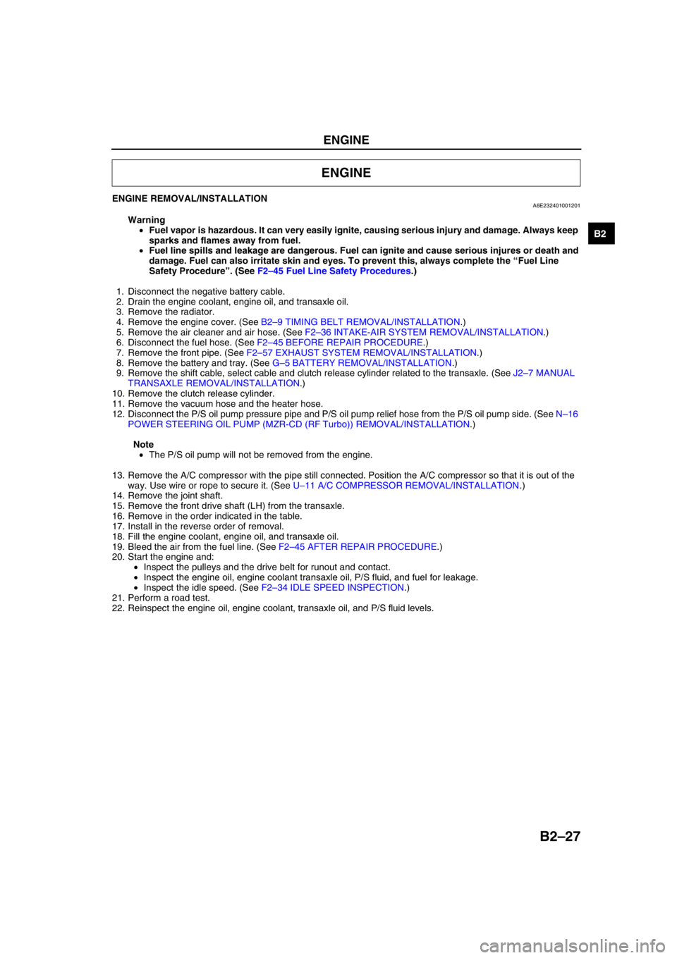
ENGINE REMOVAL/INSTALLATIONA6E232401001201
Warning
•Fuel vapor is hazardous. It can very easily ignite, causing serious injury and damage. Always keep
sparks and flames away from fuel.
•Fuel line spills and leakage are dangerous. Fuel can ignite and cause serious injures or death and
damage. Fuel can also irritate skin and eyes. To prevent this, always complete the “Fuel Line
Safety Procedure”. (See F2–45 Fuel Line Safety Procedures.)
1. Disconnect the negative battery cable.
2. Drain the engine coolant, engine oil, and transaxle oil.
3. Remove the radiator.
4. Remove the engine cover. (See B2–9 TIMING BELT REMOVAL/INSTALLATION.)
5. Remove the air cleaner and air hose. (See F2–36 INTAKE-AIR SYSTEM REMOVAL/INSTALLATION.)
6. Disconnect the fuel hose. (See F2–45 BEFORE REPAIR PROCEDURE.)
7. Remove the front pipe. (See F2–57 EXHAUST SYSTEM REMOVAL/INSTALLATION.)
8. Remove the battery and tray. (See G–5 BATTERY REMOVAL/INSTALLATION.)
9. Remove the shift cable, select cable and clutch release cylinder related to the transaxle. (See J2–7 MANUAL
TRANSAXLE REMOVAL/INSTALLATION.)
10. Remove the clutch release cylinder.
11. Remove the vacuum hose and the heater hose.
12. Disconnect the P/S oil pump pressure pipe and P/S oil pump relief hose from the P/S oil pump side. (See N–16
POWER STEERING OIL PUMP (MZR-CD (RF Turbo)) REMOVAL/INSTALLATION.)
Note
•The P/S oil pump will not be removed from the engine.
13. Remove the A/C compressor with the pipe still connected. Position the A/C compressor so that it is out of the
way. Use wire or rope to secure it. (See U–11 A/C COMPRESSOR REMOVAL/INSTALLATION.)
14. Remove the joint shaft.
15. Remove the front drive shaft (LH) from the transaxle.
16. Remove in the order indicated in the table.
17. Install in the reverse order of removal.
18. Fill the engine coolant, engine oil, and transaxle oil.
19. Bleed the air from the fuel line. (See F2–45 AFTER REPAIR PROCEDURE.)
20. Start the engine and:
•Inspect the pulleys and the drive belt for runout and contact.
•Inspect the engine oil, engine coolant transaxle oil, P/S fluid, and fuel for leakage.
•Inspect the idle speed. (See F2–34 IDLE SPEED INSPECTION.)
21. Perform a road test.
22. Reinspect the engine oil, engine coolant, transaxle oil, and P/S fluid levels.
ENGINE
Page 59 of 909

B2–28
ENGINE
5
4
3
1
2
74.5—104.9
{7.6—10.6, 55.0—76.6}
N·m {kgf·m, ft·lbf} 85.3—116.6
{8.7—11.8, 62.9—85.9}58.8—80.4
{6.0—8.1, 43.3—58.5} 74.5—104.9
{7.6—10.6, 55.0—76.6}66.6—93.1
{6.8—9.4, 49.2—67.9}
66.6—93.1
{6.8—9.4,
49.2—67.9}58.8—80.4
{6.0—8.1, 43.3—58.5}
A6E2324W200
1 No.1 Engine mount rubber
(See B2–29 No.1 Engine Mount Rubber Removal
Note)
(See B2–32 No.1 Engine Mount Rubber Installation
Note)
2 No.1 Engine mount bracket
(See B2–32 No.1 Engine Mount Bracket Installation
Note)
3 No.4 Engine mount bracket and No.4 Engine mount
rubber
(See B2–29 No.4 Engine Mount Bracket and No.4
Engine Mount Rubber Removal Note)
(See B2–31 No.4 Engine Mount Bracket and No.4
Engine Mount Rubber Installation Note)4 No.3 Engine joint bracket
(See B2–30 No.3 Engine Joint Bracket Installation
Note)
5 Engine, transaxle
Page 60 of 909

ENGINE
B2–29
B2
No.1 Engine Mount Rubber Removal Note
1. Suspend the engine using the SST.
2. Remove through-bolt A on the No.1 engine mount
bracket side.
3. Loosen through-bolt B on the front crossmember
side until approximately three pitches are
showing.
Note
•Do not remove the No.1 engine mount
rubber from the front crossmember.
No.4 Engine Mount Bracket and No.4 Engine Mount Rubber Removal Note
1. Secure the engine and the transaxle using an
engine jack and attachment as shown.
49 E017 5A0
A6E2316W101
A B
A6E2324W201
A6E2324W202
A6E2324W209
Page 61 of 909

B2–30
ENGINE
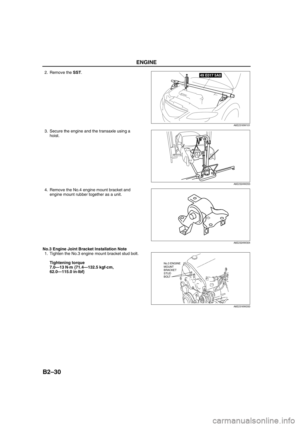
2. Remove the SST.
3. Secure the engine and the transaxle using a
hoist.
4. Remove the No.4 engine mount bracket and
engine mount rubber together as a unit.
No.3 Engine Joint Bracket Installation Note
1. Tighten the No.3 engine mount bracket stud bolt.
Tightening torque
7.0—13 N·m {71.4—132.5 kgf·cm,
62.0—115.0 in·lbf}49 E017 5A0
A6E2316W101
A6E2324W203
A6E2324W304
No.3 ENGINE
MOUNT
BRACKET
STUD
BOLT
A6E2316W200
Page 62 of 909

ENGINE
B2–31
B2
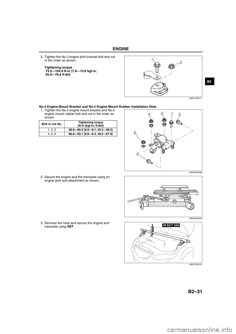
2. Tighten the No.3 engine joint bracket bolt and nut
in the order as shown.
Tightening torque
74.5—104.9 N·m {7.6—10.6 kgf·m,
55.0—76.6 ft·lbf}
No.4 Engine Mount Bracket and No.4 Engine Mount Rubber Installation Note
1. Tighten the No.4 engine mount bracket and No.4
engine mount rubber bolt and nut in the order as
shown.
2. Secure the engine and the transaxle using an
engine jack and attachment as shown.
3. Remove the hoist and secure the engine and
transaxle using SST.12
A6E2316W111
Bolt or nut No.Tightening torque
(N·m {kgf·m, ft·lbf})
1, 2, 358.8—80.4 {6.0—8.1, 43.3—58.5}
4, 5, 666.6—93.1 {6.8—9.4, 49.2—67.9}
5431
2
6
A6E2324W306
A6E2324W209
49 E017 5A0
A6E2316W101
Page 63 of 909

B2–32
ENGINE
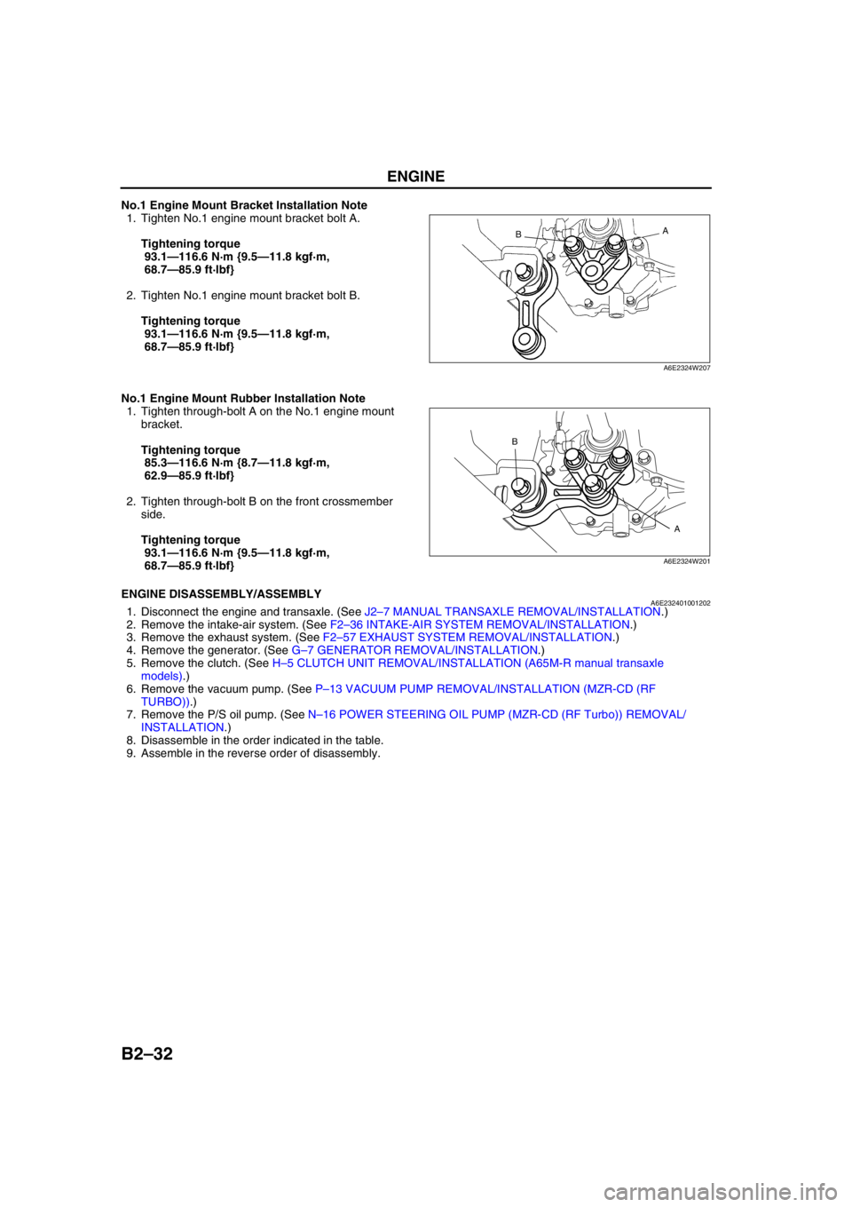
No.1 Engine Mount Bracket Installation Note
1. Tighten No.1 engine mount bracket bolt A.
Tightening torque
93.1—116.6 N·m {9.5—11.8 kgf·m,
68.7—85.9 ft·lbf}
2. Tighten No.1 engine mount bracket bolt B.
Tightening torque
93.1—116.6 N·m {9.5—11.8 kgf·m,
68.7—85.9 ft·lbf}
No.1 Engine Mount Rubber Installation Note
1. Tighten through-bolt A on the No.1 engine mount
bracket.
Tightening torque
85.3—116.6 N·m {8.7—11.8 kgf·m,
62.9—85.9 ft·lbf}
2. Tighten through-bolt B on the front crossmember
side.
Tightening torque
93.1—116.6 N·m {9.5—11.8 kgf·m,
68.7—85.9 ft·lbf}
End Of SieENGINE DISASSEMBLY/ASSEMBLYA6E2324010012021. Disconnect the engine and transaxle. (See J2–7 MANUAL TRANSAXLE REMOVAL/INSTALLATION.)
2. Remove the intake-air system. (See F2–36 INTAKE-AIR SYSTEM REMOVAL/INSTALLATION.)
3. Remove the exhaust system. (See F2–57 EXHAUST SYSTEM REMOVAL/INSTALLATION.)
4. Remove the generator. (See G–7 GENERATOR REMOVAL/INSTALLATION.)
5. Remove the clutch. (See H–5 CLUTCH UNIT REMOVAL/INSTALLATION (A65M-R manual transaxle
models).)
6. Remove the vacuum pump. (See P–13 VACUUM PUMP REMOVAL/INSTALLATION (MZR-CD (RF
TURBO)).)
7. Remove the P/S oil pump. (See N–16 POWER STEERING OIL PUMP (MZR-CD (RF Turbo)) REMOVAL/
INSTALLATION.)
8. Disassemble in the order indicated in the table.
9. Assemble in the reverse order of disassembly.
A
B
A6E2324W207
A B
A6E2324W201
Page 64 of 909

ENGINE
B2–33
B2
.
A/C Compressor Bracket Installation Note
1. Tighten the A/C compressor bracket bolts in the
order shown.
Tightening torque
38—51 N·m {3.8—5.3 kgf·m, 28—38 ft·lbf}
End Of Sie
N·m { kgf·m, ft·lbf} 38—51
{3.8—5.3, 28—38}
1
2
A6E2324W105
1 A/C compressor bracket
(See B2–33 A/C Compressor Bracket Installation
Note)2 Seal plate
43
1
2
A6E2324W106