engine MAZDA 6 2002 Suplement Repair Manual
[x] Cancel search | Manufacturer: MAZDA, Model Year: 2002, Model line: 6, Model: MAZDA 6 2002Pages: 909, PDF Size: 17.16 MB
Page 65 of 909

D–1
D
DLUBRICATION SYSTEM
OUTLINE................................................................ D-2
OUTLINE OF CONSTRUCTION.......................... D-2
SPECIFICATIONS ............................................... D-2
STRUCTURAL VIEW ...........................................D-4
LUBRICATION SYSTEM........................................ D-5
LUBRICATION FLOW CHART ............................ D-5
OUTLINE................................................................ D-6
SUPPLEMENTAL SERVICE INFORMATION .....D-6
LUBRICATION SYSTEM........................................ D-6
LOCATION INDEX ............................................... D-6
OIL PRESSURE INSPECTION..............................D-7
OIL PRESSURE INSPECTION............................ D-7
ENGINE OIL........................................................... D-8
ENGINE OIL INSPECTION.................................. D-8
ENGINE OIL REPLACEMENT.............................D-8
OIL FILTER............................................................. D-9
OIL FILTER REPLACEMENT ..............................D-9
OIL COOLER.......................................................... D-9
OIL COOLER REMOVAL/INSTALLATION ..........D-9
OIL PAN................................................................ D-10
OIL PAN REMOVAL/INSTALLATION................ D-10 FEATURES
SERVICE
Page 66 of 909

D–2
OUTLINE
OUTLINE OF CONSTRUCTIONA6E330202000201•The construction and the operation of the oil cooler and the oil filter for the new Mazda6 (GG, GY) MZR-CD (RF
Turbo) engine model is the same as the current Mazda MPV (LW) MZR-CD (RF Turbo) engine model. (See
Mazda MPV Workshop Manual Supplement 1737-1*-02D.)
•The construction and the operation of the lubrication system except for the oil cooler and oil filter for the new
Mazda6 (GG, GY) MZR-CD (RF Turbo) engine model is the same as the current Mazda 626, 626 Station
Wagon (GF, GW) RF Turbo engine model. (European specs.) (See Mazda 626, 626 Station Wagon RF Turbo
Workshop Manual Supplement 1614-10-98D.)
•The construction and the operation of the lubrication system for the new Mazda6 (GG, GY) L8, LF, and L3
engine models is the same as the current Mazda6 (GG) engine model L8, LF, and L3 engine models. (See
Mazda6 Training Manual 3359-1*-02C, Mazda6 Workshop Manual 1730-1*-02C.)
End Of Sie
SPECIFICATIONSA6E330202000202Gasoline engine
* : Always verify the oil level with the dipsticks since the engine oil capacity differs according to dipstick
specifications. (See Mazda6 Workshop Manual 1730-1*-02C Section D.)
Recommended Engine Oil (Gasoline Engine)
•The maintenance intervals on the scheduled maintenance table (See GI–8 SCHEDULED MAINTENANCE
TABLE) can only be supported with the use of following oils.
OUTLINE
ItemSpecification
New
Mazda6
(GG, GY)Current
Mazda6
(GG)New
Mazda6
(GG, GY)Current
Mazda6
(GG)New
Mazda6
(GG, GY)Current
Mazda6
(GG)
L8 LF L3*
Lubrication system Force-fed type
Oil coolerWater-cooled
Oil pressure
(approximate quantity)
[oil temperature: 100°C
{212°F}](kPa {kgf/cm
2, psi})
min [rpm]234—521
{2.39—5.31, 33.9—75.5}
[3,000]395—649
{4.03—6.61,
57.3—94.1}
[3,000]
Oil pumpType Trochoid gear type
Relief pressure
(approximate
quantity) (kPa {kgf/cm
2,
psi})500—600
{5.09—6.11, 72.6—87.0}
Oil filterType Full-flow, Paper element
Bypass pressure
(approximate
quantity)(kPa kgf/cm
2, psi})80—120
{0.9—1.2, 12.8—17.0}
Oil capacity
(approximate
quantity)Total
(dry engine)(L {US qt, lmp qt}) 4.6 {4.8, 4.0} Dipstick A: 4.2 {4.4, 3.7}
Dipstick B: 5.1 {5.4, 4.5}
Oil replacement (L {US qt, lmp qt}) 3.9 {4.0, 3.4} Dipstick A: 3.1 {3.3, 2.7}
Dipstick B: 4.0 {4.2, 3.5}
Oil and oil filter
replacement(L {US qt, lmp qt}) 4.3 {4.5, 3.8} Dipstick A: 3.5 {3.7, 3.1}
Dipstick B: 4.4 {4.6, 3.9}
ItemSpecification
New Mazda6
(GG, GY), Current Mazda6
(GG)New Mazda6
(GG, GY), Current Mazda6
(GG)
L8, LF, L3
Engine oil GradeAPI SL
ACEA A3
Viscosity (SAE) 5W-30, 10W-40 5W-20
RemarksMazda genuine Dexelia oil e.g. —
Page 67 of 909

OUTLINE
D–3
D
Diesel engine
Bold frames: New specifications
Recommended Engine Oil (Diesel Engine)
•The maintenance intervals on the scheduled maintenance table (See GI–8 SCHEDULED MAINTENANCE
TABLE) can only be supported with the use of following oils.
Bold frames: New specifications
End Of Sie
ItemSpecification
New Mazda6
(GG, GY)Current
Mazda 626, 626
Station Wagon
(GF, GW)Current
Mazda MPV
(LW)
MZR-CD (RF Turbo) RF TurboMZR-CD (RF
Turbo)
Lubrication system Force-fed type—
Oil cooler Water-cooled—
Oil pressure
(approximate quantity)
[oil temperature: 100°C {212°F}](kPa {kgf/cm
2, psi})
min [rpm]147 {1.5, 21} [1,000],
343 {3.5, 50} [3,000]—
Oil pumpType Trochoid gear type—Trochoid gear type
Relief pressure
(approximate
quantity)(kPa {kgf/cm
2, psi})
[rpm]580—700
{5.9—7.1,
84.1—101.5}
[3,000]—580—700
{5.9—7.1,
84.1—101.5}
[3,000]
Oil filterTypeFull-flow,
Paper element—Full-flow,
Paper element
Bypass pressure
(approximate
quantity)(kPa kgf/cm
2, psi})78—118
{0.8—1.2,
11.3—17.1} —78—118
{0.8—1.2,
11.3—17.1}
Oil capacity
(approximate
quantity)Total
(dry engine)(L {US qt, lmp qt}) 5.5 {5.8, 4.8} 5.4 {5.7, 4.8} —
Oil replacement (L {US qt, lmp qt}) 4.8 {5.1, 4.2} 4.5 {4.8, 4.0}—
Oil and oil filter
replacement(L {US qt, lmp qt}) 5.0 {5.3 ,4.4} 4.7 {5.0, 4.1} —
ItemSpecification
New Mazda6
(GG, GY)Current
Mazda 626, 626
Station Wagon
(GF, GW)
MZR-CD (RF Turbo) RF Turbo
Engine oil GradeAPI CF CD, CE, CF-4 CD
ACEA B1 or B3 B3 B3 or B4—
Viscosity (SAE) 5W-30 10W-40 5W-30, 10W-30 5W-30, 10W-30
RemarksMazda genuine
Dexelia oil e.g.——
Page 70 of 909

D–6
OUTLINE, LUBRICATION SYSTEM
SUPPLEMENTAL SERVICE INFORMATIONA6E330202000204•The following changes and/or additions have been made since publication of the Mazda6 Workshop Manual
(1730-1*-02C).
Oil pressure
•Inspection procedure has been adopted. (MZR-CD (RF Turbo) engine model)
Engine oil
•Inspection procedure has been adopted. (MZR-CD (RF Turbo) engine model)
•Replacement procedure has been adopted. (MZR-CD (RF Turbo) engine model)
Oil filter
•Replacement procedure has been adopted. (MZR-CD (RF Turbo) engine model)
Oil cooler
•Removal/Installation procedure has been adopted. (MZR-CD (RF Turbo) engine model)
Oil pan
•Removal/Installation procedure has been adopted. (MZR-CD (RF Turbo) engine model)
End Of Sie
LOCATION INDEXA6E333014100201MZR-CD (RF Turbo)
.
End Of Sie
OUTLINE
LUBRICATION SYSTEM
4
3
1
2
A6E3300W003
1 Oil pressure switch
(See D–7 OIL PRESSURE INSPECTION)
2 Oil filter
(See D–9 OIL FILTER REPLACEMENT)3 Oil cooler
(See D–9 OIL COOLER REMOVAL/
INSTALLATION)
4 Oil pan
(See D–10 OIL PAN REMOVAL/INSTALLATION)
Page 71 of 909
OIL PRESSURE INSPECTION
D–7
D
OIL PRESSURE INSPECTIONA6E331001003201MZR-CD (RF Turbo)
Warning
•Continuous exposure to USED engine oil has caused skin cancer in laboratory mice. Protect your
skin by washing with soap and water immediately after working with engine oil.
•Hot engines and engine oil can cause severe burns. Turn off the engine and wait until it and the
engine oil have cooled.
1. Disconnect the negative battery cable.
2. Remove the under cover.
3. Remove the oil pressure switch.
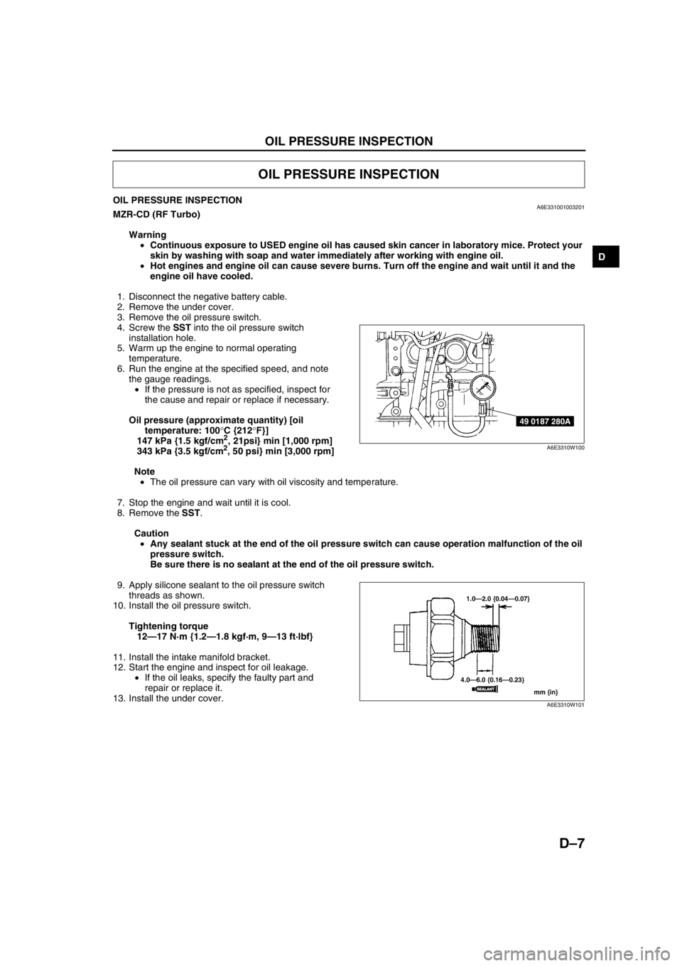
4. Screw the SST into the oil pressure switch
installation hole.
5. Warm up the engine to normal operating
temperature.
6. Run the engine at the specified speed, and note
the gauge readings.
•If the pressure is not as specified, inspect for
the cause and repair or replace if necessary.
Oil pressure (approximate quantity) [oil
temperature: 100°C {212°F}]
147 kPa {1.5 kgf/cm
2, 21psi} min [1,000 rpm]
343 kPa {3.5 kgf/cm2, 50 psi} min [3,000 rpm]
Note
•The oil pressure can vary with oil viscosity and temperature.
7. Stop the engine and wait until it is cool.
8. Remove the SST.
Caution
•Any sealant stuck at the end of the oil pressure switch can cause operation malfunction of the oil
pressure switch.
Be sure there is no sealant at the end of the oil pressure switch.
9. Apply silicone sealant to the oil pressure switch
threads as shown.
10. Install the oil pressure switch.
Tightening torque
12—17 N·m {1.2—1.8 kgf·m, 9—13 ft·lbf}
11. Install the intake manifold bracket.
12. Start the engine and inspect for oil leakage.
•If the oil leaks, specify the faulty part and
repair or replace it.
13. Install the under cover.
End Of Sie
OIL PRESSURE INSPECTION
49 0187 280A
A6E3310W100
1.0—2.0 {0.04—0.07}
4.0—6.0 {0.16—0.23}
mm {in}
SEALANTSEALANT
A6E3310W101
Page 72 of 909
D–8
ENGINE OIL
ENGINE OIL INSPECTIONA6E331214001201MZR-CD (RF Turbo)
1. Position the vehicle on level ground.
2. Warm up the engine to normal operating temperature.
3. Stop the engine and wait for 5 min.
4. Verify that the oil level is between the L and F marks on the dipstick and check the engine oil condition.
•If the oil level is below the L mark, add engine oil. (See D–8 ENGINE OIL REPLACEMENT.)
End Of SieENGINE OIL REPLACEMENTA6E331214001202MZR-CD (RF Turbo)
Warning
•Hot engines and engine oil can cause severe burns. Turn off the engine and wait until it and the
engine oil have cooled.
•A vehicle that is lifted but not securely supported on safety stands is dangerous. It can slip or fall,
causing death or serious injury. Never work around or under a lifted vehicle if it is not securely
supported on safety stands.
•Continuous exposure to USED engine oil has caused skin cancer in laboratory mice. Protect your
skin by washing with soap and water immediately after working with engine oil.
Caution
•In case you spill engine oil on the front pipe, wipe it off completely. If you fail to wipe the spilled
oil, it will produce fumes because of the heat.
1. Position the vehicle on level ground.
2. Remove the the oil filler cap.
3. Remove the under cover.
4. Remove the oil pan drain plug.
5. Drain the engine oil into a container.
6. Install the oil pan drain plug with a new the washer.
Tightening torque
12—17 N·m {1.2—1.8 kgf·m, 9—13 ft·lbf}
Note
•The amount of residual oil in the engine can vary with the replacement method, oil temperature, etc. Verify
the oil level after engine oil replacement.
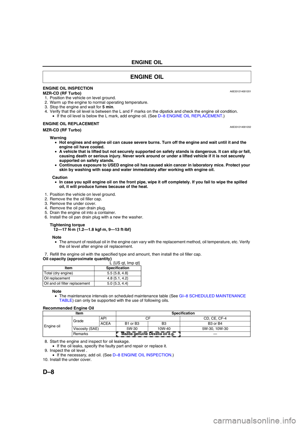
7. Refill the engine oil with the specified type and amount, then install the oil filler cap.
Oil capacity (approximate quantity)
L {US qt, Imp qt}
Note
•The maintenance intervals on scheduled maintenance table (See GI–8 SCHEDULED MAINTENANCE
TABLE) can only be supported with the use of following oils.
Recommended Engine Oil
8. Start the engine and inspect for oil leakage.
•If the oil leaks, specify the faulty part and repair or replace it.
9. Inspect the oil level .
•If the necessary, add oil. (See D–8 ENGINE OIL INSPECTION.)
10. Install the under cover.
End Of Sie
ENGINE OIL
Item Specification
Total (dry engine) 5.5 {5.8, 4.8}
Oil replacement 4.8 {5.1, 4.2}
Oil and oil filter replacement 5.0 {5.3, 4.4}
Item Specification
Engine oil GradeAPI CF CD, CE, CF-4
ACEA B1 or B3 B3 B3 or B4
Viscosity (SAE) 5W-30 10W-40 5W-30, 10W-30
RemarksMazda genuine Dexelia oil e.g. —
Page 73 of 909
OIL FILTER, OIL COOLER
D–9
D
OIL FILTER REPLACEMENTA6E331414300201MZR-CD (RF Turbo)
1. Disconnect the negative battery cable.
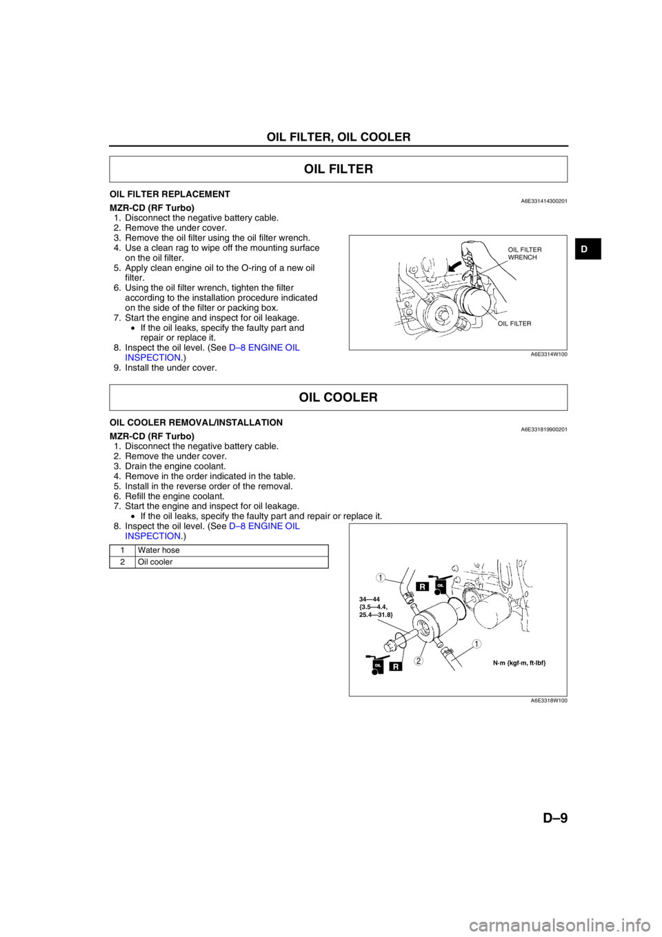
2. Remove the under cover.
3. Remove the oil filter using the oil filter wrench.
4. Use a clean rag to wipe off the mounting surface
on the oil filter.
5. Apply clean engine oil to the O-ring of a new oil
filter.
6. Using the oil filter wrench, tighten the filter
according to the installation procedure indicated
on the side of the filter or packing box.
7. Start the engine and inspect for oil leakage.
•If the oil leaks, specify the faulty part and
repair or replace it.
8. Inspect the oil level. (See D–8 ENGINE OIL
INSPECTION.)
9. Install the under cover.
End Of Sie
OIL COOLER REMOVAL/INSTALLATIONA6E331819900201MZR-CD (RF Turbo)
1. Disconnect the negative battery cable.
2. Remove the under cover.
3. Drain the engine coolant.
4. Remove in the order indicated in the table.
5. Install in the reverse order of the removal.
6. Refill the engine coolant.
7. Start the engine and inspect for oil leakage.
•If the oil leaks, specify the faulty part and repair or replace it.
8. Inspect the oil level. (See D–8 ENGINE OIL
INSPECTION.)
.
End Of Sie
OIL FILTER
OIL FILTER
WRENCH
OIL FILTER
A6E3314W100
OIL COOLER
1 Water hose
2 Oil cooler
ROILOIL
34—44
{3.5—4.4,
25.4—31.8}
1
2N·m {kgf·m, ft·lbf}ROILOIL
1
A6E3318W100
Page 74 of 909
D–10
OIL PAN
OIL PAN REMOVAL/INSTALLATIONA6E332010040201MZR-CD (RF Turbo)
Warning
•Hot engines and engines oil can cause severe burns. Turn off the engine and wait until it and the
engine oil have cooled.
1. Disconnect the negative battery cable.
2. Remove the under cover.
3. Drain the engine oil. (See D–8 ENGINE OIL REPLACEMENT.)
4. Remove the lower radiator hose assembly under the oil pan with the cooling hose still connected. Position the
lower radiator hose assembly so that it is out of the way.
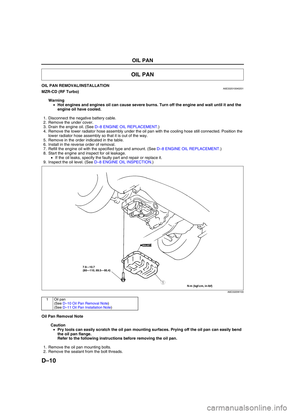
5. Remove in the order indicated in the table.
6. Install in the reverse order of removal.
7. Refill the engine oil with the specified type and amount. (See D–8 ENGINE OIL REPLACEMENT.)
8. Start the engine and inspect for oil leakage.
•If the oil leaks, specify the faulty part and repair or replace it.
9. Inspect the oil level. (See D–8 ENGINE OIL INSPECTION.)
.
Oil Pan Removal Note
Caution
•Pry tools can easily scratch the oil pan mounting surfaces. Prying off the oil pan can easily bend
the oil pan flange.
Refer to the following instructions before removing the oil pan.
1. Remove the oil pan mounting bolts.
2. Remove the sealant from the bolt threads.
OIL PAN
7.9—10.7
{80—110, 69.5—95.4}
N·m {kgf·cm, in·lbf}
1
SEALANTSEALANT
A6E3320W100
1Oil pan
(See D–10 Oil Pan Removal Note)
(See D–11 Oil Pan Installation Note)
Page 76 of 909
E–1
E
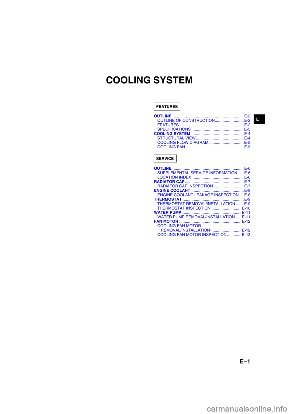
ECOOLING SYSTEM
OUTLINE................................................................ E-2
OUTLINE OF CONSTRUCTION.......................... E-2
FEATURES .......................................................... E-2
SPECIFICATIONS ............................................... E-3
COOLING SYSTEM................................................ E-4
STRUCTURAL VIEW ........................................... E-4
COOLING FLOW DIAGRAM ............................... E-5
COOLING FAN .................................................... E-5
OUTLINE................................................................ E-6
SUPPLEMENTAL SERVICE INFORMATION ..... E-6
LOCATION INDEX ............................................... E-6
RADIATOR CAP..................................................... E-7
RADIATOR CAP INSPECTION ........................... E-7
ENGINE COOLANT................................................ E-8
ENGINE COOLANT LEAKAGE INSPECTION .... E-8
THERMOSTAT....................................................... E-9
THERMOSTAT REMOVAL/INSTALLATION ....... E-9
THERMOSTAT INSPECTION ........................... E-10
WATER PUMP...................................................... E-11
WATER PUMP REMOVAL/INSTALLATION...... E-11
FAN MOTOR........................................................ E-12
COOLING FAN MOTOR
REMOVAL/INSTALLATION ............................ E-12
COOLING FAN MOTOR INSPECTION ............. E-13 FEATURES
SERVICE
Page 77 of 909

E–2
OUTLINE
OUTLINE OF CONSTRUCTIONA6E360202000205•The construction and operation of the water pump and the thermostat for the new Mazda6 (GG, GY) MZR-CD
(RF Turbo) engine model are the same as the current Mazda 323 (BJ) RF Turbo engine model. (European
specs.) (See Mazda 323 RF Turbo Workshop Manual Supplement 1633-10-98G.)
•The construction and operation of the cooling system except for the water pump and the thermostat for the new
Mazda6 (GG, GY) MZR-CD (RF Turbo) engine model are the same as the current Mazda6 (GG) L3 engine
model except for the following features. (See Mazda6 Training Manual 3359-1*-02C.)
•The construction and operation of the engine cooling system for the new Mazda6 (GG, GY) L8, LF, and L3
engine models is the same as the current Mazda6 (GG) L8, LF, and L3 engine models. (See Mazda6 Training
Manual 3359-1*-02C.)
End Of Sie
FEATURESA6E360202000206Modification to fit the engine performance
•Cooling fan motor output has been changed. (MZR-CD (RF Turbo) engine model)
End Of Sie
OUTLINE