clutch MAZDA 6 2002 Suplement Manual PDF
[x] Cancel search | Manufacturer: MAZDA, Model Year: 2002, Model line: 6, Model: MAZDA 6 2002Pages: 909, PDF Size: 17.16 MB
Page 455 of 909
K2–40
AUTOMATIC TRANSAXLE
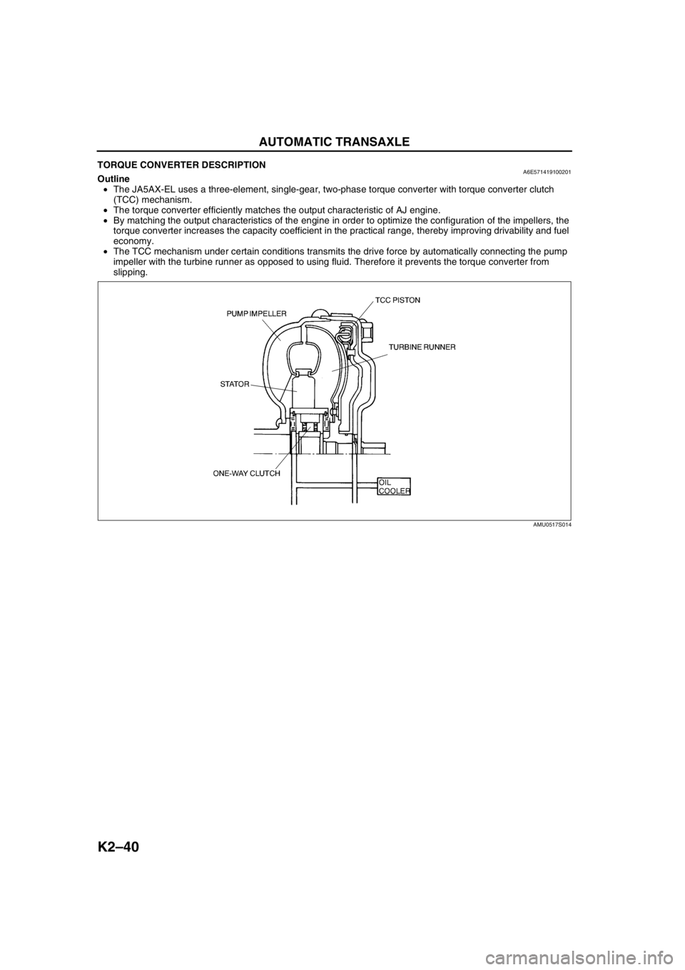
TORQUE CONVERTER DESCRIPTIONA6E571419100201Outline
•The JA5AX-EL uses a three-element, single-gear, two-phase torque converter with torque converter clutch
(TCC) mechanism.
•The torque converter efficiently matches the output characteristic of AJ engine.
•By matching the output characteristics of the engine in order to optimize the configuration of the impellers, the
torque converter increases the capacity coefficient in the practical range, thereby improving drivability and fuel
economy.
•The TCC mechanism under certain conditions transmits the drive force by automatically connecting the pump
impeller with the turbine runner as opposed to using fluid. Therefore it prevents the torque converter from
slipping.
End Of Sie
AMU0517S014
Page 457 of 909
K2–42
AUTOMATIC TRANSAXLE
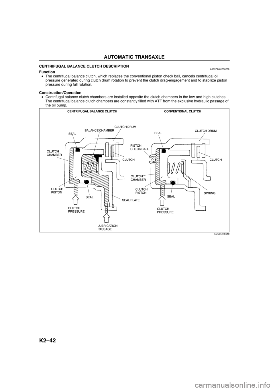
CENTRIFUGAL BALANCE CLUTCH DESCRIPTIONA6E571401030208Function
•The centrifugal balance clutch, which replaces the conventional piston check ball, cancels centrifugal oil
pressure generated during clutch drum rotation to prevent the clutch drag-engagement and to stabilize piston
pressure during full rotation.
Construction/Operation
•Centrifugal balance clutch chambers are installed opposite the clutch chambers in the low and high clutches.
The centrifugal balance clutch chambers are constantly filled with ATF from the exclusive hydraulic passage of
the oil pump.
AMU0517S018
Page 458 of 909
AUTOMATIC TRANSAXLE
K2–43
K2
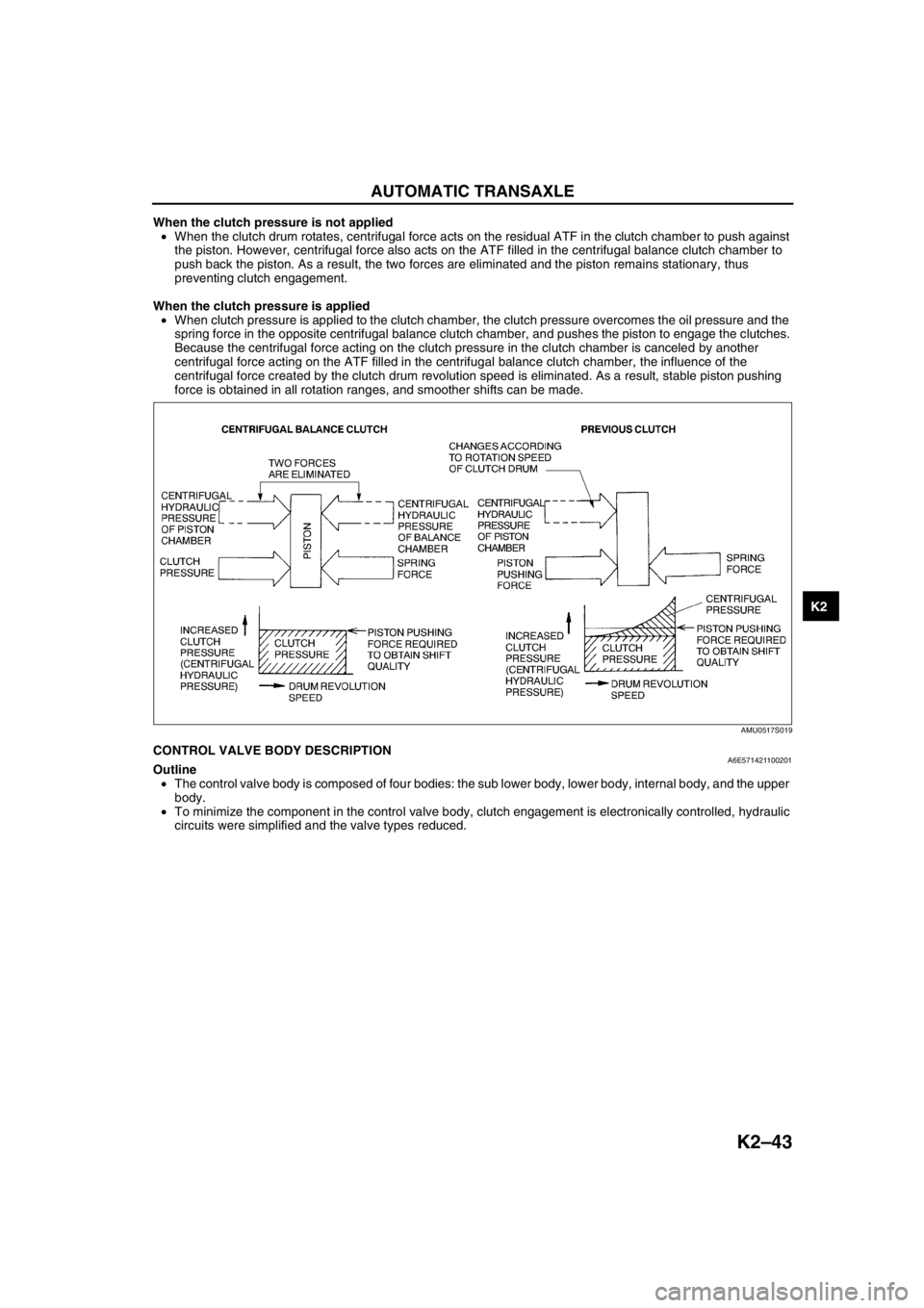
When the clutch pressure is not applied
•When the clutch drum rotates, centrifugal force acts on the residual ATF in the clutch chamber to push against
the piston. However, centrifugal force also acts on the ATF filled in the centrifugal balance clutch chamber to
push back the piston. As a result, the two forces are eliminated and the piston remains stationary, thus
preventing clutch engagement.
When the clutch pressure is applied
•When clutch pressure is applied to the clutch chamber, the clutch pressure overcomes the oil pressure and the
spring force in the opposite centrifugal balance clutch chamber, and pushes the piston to engage the clutches.
Because the centrifugal force acting on the clutch pressure in the clutch chamber is canceled by another
centrifugal force acting on the ATF filled in the centrifugal balance clutch chamber, the influence of the
centrifugal force created by the clutch drum revolution speed is eliminated. As a result, stable piston pushing
force is obtained in all rotation ranges, and smoother shifts can be made.
End Of SieCONTROL VALVE BODY DESCRIPTIONA6E571421100201Outline
•The control valve body is composed of four bodies: the sub lower body, lower body, internal body, and the upper
body.
•To minimize the component in the control valve body, clutch engagement is electronically controlled, hydraulic
circuits were simplified and the valve types reduced.
AMU0517S019
Page 460 of 909
AUTOMATIC TRANSAXLE
K2–45
K2
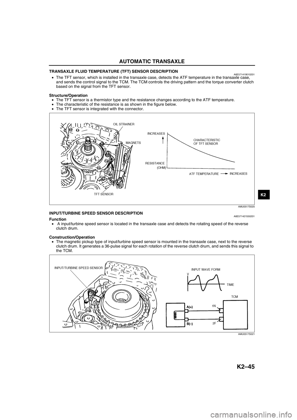
TRANSAXLE FLUID TEMPERATURE (TFT) SENSOR DESCRIPTIONA6E571419010201•The TFT sensor, which is installed in the transaxle case, detects the ATF temperature in the transaxle case,
and sends the control signal to the TCM. The TCM controls the driving pattern and the torque converter clutch
based on the signal from the TFT sensor.
Structure/Operation
•The TFT sensor is a thermistor type and the resistance changes according to the ATF temperature.
•The characteristic of the resistance is as shown in the figure below.
•The TFT sensor is integrated with the connector.
End Of SieINPUT/TURBINE SPEED SENSOR DESCRIPTIONA6E571421550201Function
• A input/turbine speed sensor is located in the transaxle case and detects the rotating speed of the reverse
clutch drum.
Construction/Operation
•The magnetic pickup type of input/turbine speed sensor is mounted in the transaxle case, next to the reverse
clutch drum. It generates a 36-pulse signal for each rotation of the reverse clutch drum, and sends this signal to
the TCM.
End Of Sie
AMU0517S020
AMU0517S021
Page 463 of 909
K2–48
AUTOMATIC TRANSAXLE
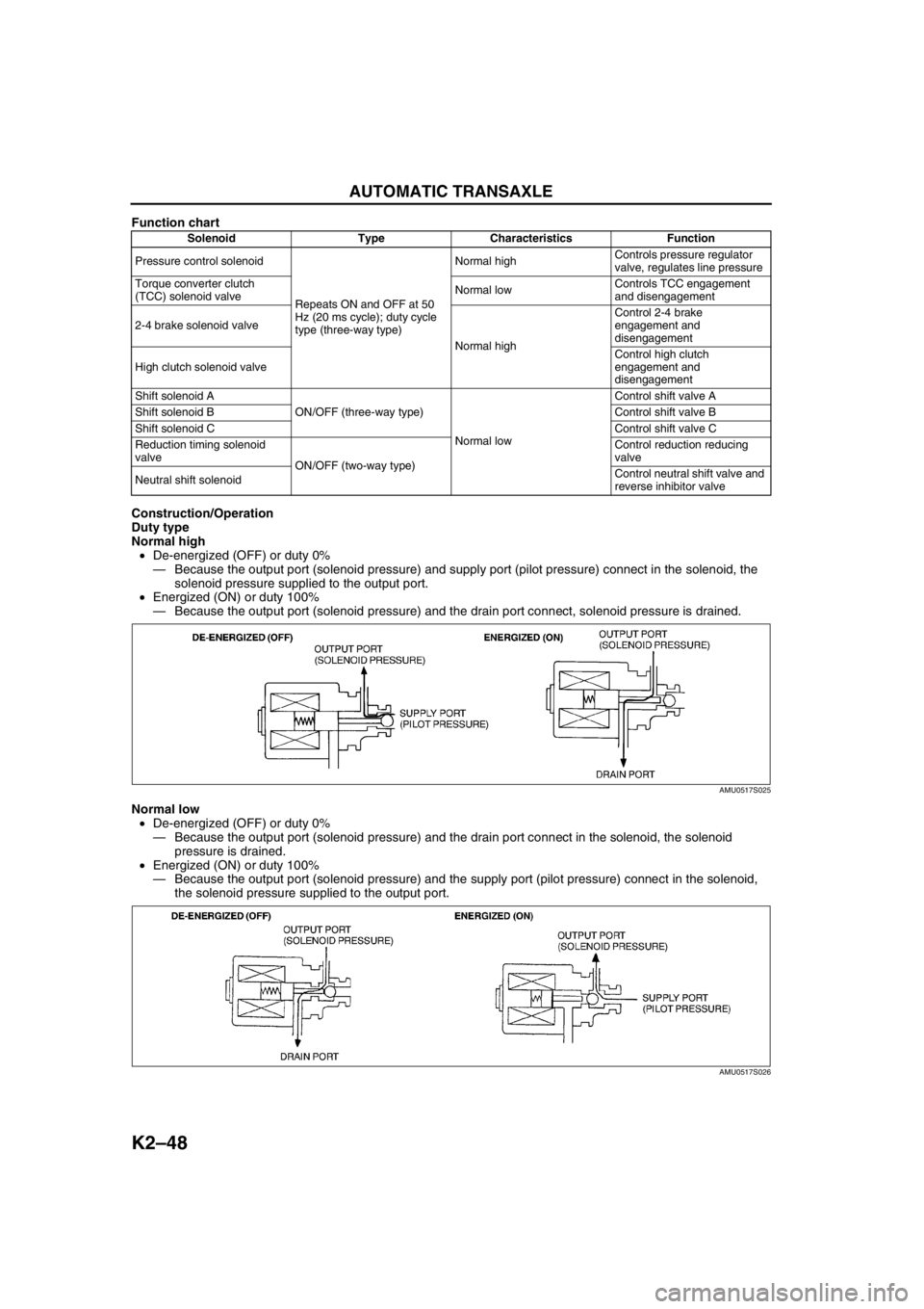
Function chart
Construction/Operation
Duty type
Normal high
•De-energized (OFF) or duty 0%
—Because the output port (solenoid pressure) and supply port (pilot pressure) connect in the solenoid, the
solenoid pressure supplied to the output port.
•Energized (ON) or duty 100%
—Because the output port (solenoid pressure) and the drain port connect, solenoid pressure is drained.
Normal low
•De-energized (OFF) or duty 0%
—Because the output port (solenoid pressure) and the drain port connect in the solenoid, the solenoid
pressure is drained.
•Energized (ON) or duty 100%
—Because the output port (solenoid pressure) and the supply port (pilot pressure) connect in the solenoid,
the solenoid pressure supplied to the output port.
Solenoid Type Characteristics Function
Pressure control solenoid
Repeats ON and OFF at 50
Hz (20 ms cycle); duty cycle
type (three-way type)Normal highControls pressure regulator
valve, regulates line pressure
Torque converter clutch
(TCC) solenoid valveNormal lowControls TCC engagement
and disengagement
2-4 brake solenoid valve
Normal highControl 2-4 brake
engagement and
disengagement
High clutch solenoid valveControl high clutch
engagement and
disengagement
Shift solenoid A
ON/OFF (three-way type)
Normal lowControl shift valve A
Shift solenoid BControl shift valve B
Shift solenoid CControl shift valve C
Reduction timing solenoid
valve
ON/OFF (two-way type)Control reduction reducing
valve
Neutral shift solenoidControl neutral shift valve and
reverse inhibitor valve
AMU0517S025
AMU0517S026
Page 467 of 909
K2–52
AUTOMATIC TRANSAXLE
Operation
Range determination
•Each range is determined by operating the selector lever, and switching ON/OFF the switch in the TR switch
internal circuit. The present range is detected according to the ON/OFF signal of the switch.
•The following switches are built into the TR switch, and determine each range when the switch is on.
P position switch
R position switch
N position switch
D range switch
End Of Sie
MANUAL MODE SHIFT CONTROL DESCRIPTIONA6E571418901204Outline
Features
•The manual mode shift control is activated by moving the selector lever from the D to M range position (selector
lever is shifted over toward front passenger side).
•Manual mode shift control with a manual shifting system allowing selection of gear positions by manual
operation of the selector lever forward (-) and back (+) has been adopted. Moreover, engine braking for all
gears in manual mode according to the gear ratio is available.
— Shifting between 1GR and 2GR when the vehicle is stopped is possible.
— When shifting from the D to M range while driving, the same gear position is maintained.
— Consecutive shifting in the M range has been adopted. When shifting down from M range 4GR or 3GR, one
gear can be skipped over by rapidly tapping the selector lever two times in the down-shift (-) direction.
•Selector lever position and gear position indicator lights, built into the instrument cluster, have been adopted.
— The selector indicator light includes a selector lever position indicator that displays selector lever positions
and, a gear position indicator light that displays gear positions.
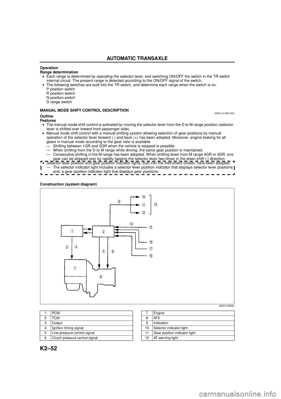
Construction (system diagram)
.
9
8
7
5
43
12
10
18
17
15
16
14
1311
12
6
A6E5714W065
1PCM
2TCM
3Output
4 Ignition timing signal
5 Line pressure control signal
6 Clutch pressure control signal7Engine
8ATX
9 Indication
10 Selector indicator light
11 Gear position indicator light
12 AT warning light
Page 469 of 909
K2–54
AUTOMATIC TRANSAXLE
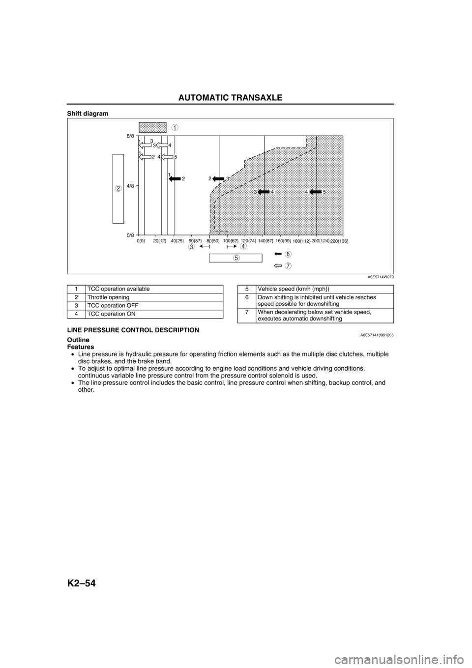
Shift diagram
.
End Of SieLINE PRESSURE CONTROL DESCRIPTIONA6E571418901205Outline
Features
•Line pressure is hydraulic pressure for operating friction elements such as the multiple disc clutches, multiple
disc brakes, and the brake band.
•To adjust to optimal line pressure according to engine load conditions and vehicle driving conditions,
continuous variable line pressure control from the pressure control solenoid is used.
•The line pressure control includes the basic control, line pressure control when shifting, backup control, and
other.
8/8
4/8
0/813
3
1
2 4
4
5 1
2
0{0} 20{12} 40{25} 60{37} 80{50} 100{62} 120{74} 140{87} 160{99}
180{112}200{124}
220{136}
2
3
34 4 5
7
5
43
1
2
6
A6E5714W070
1 TCC operation available
2 Throttle opening
3 TCC operation OFF
4 TCC operation ON5 Vehicle speed (km/h {mph})
6 Down shifting is inhibited until vehicle reaches
speed possible for downshifting
7 When decelerating below set vehicle speed,
executes automatic downshifting
Page 471 of 909
K2–56
AUTOMATIC TRANSAXLE
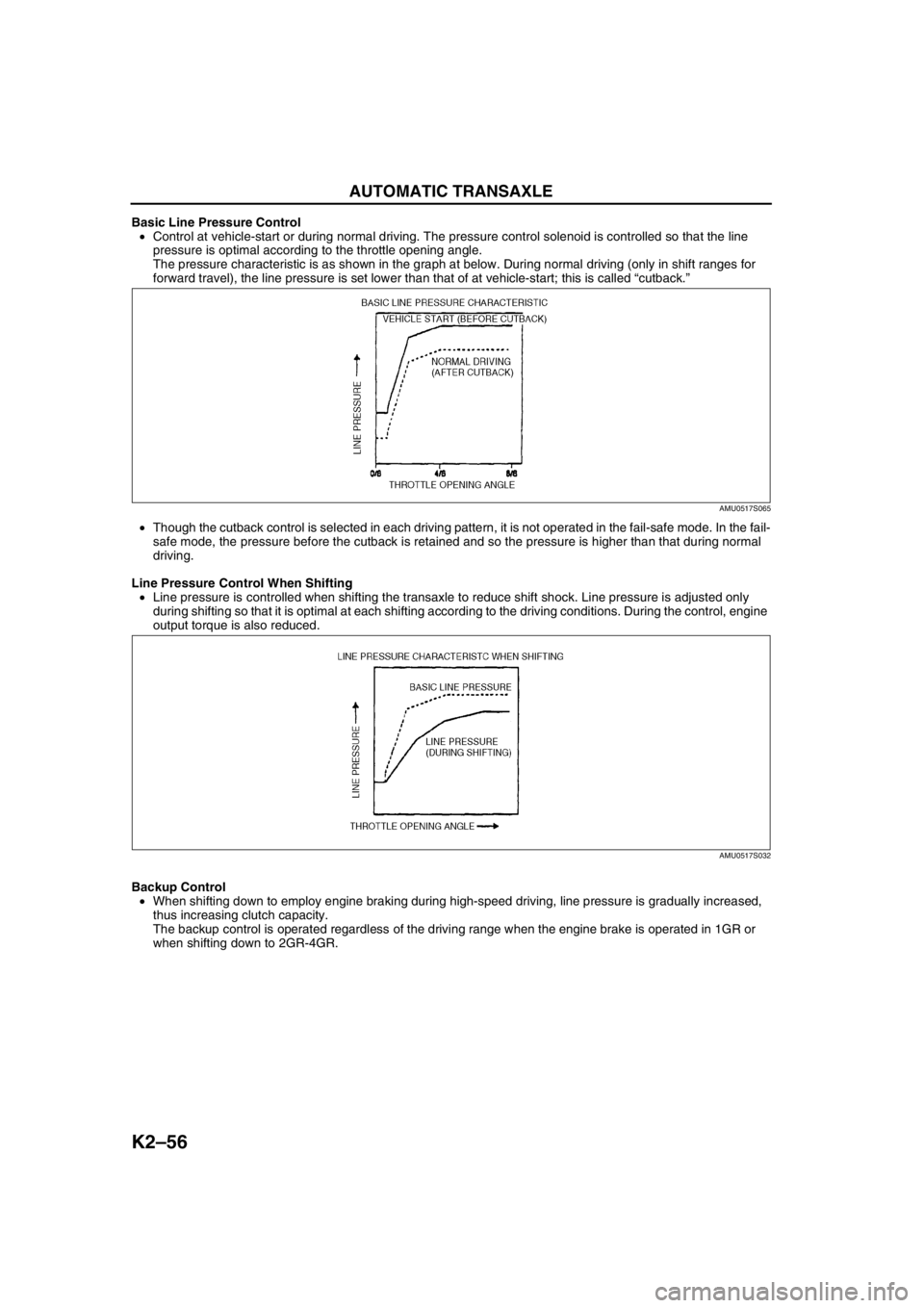
Basic Line Pressure Control
•Control at vehicle-start or during normal driving. The pressure control solenoid is controlled so that the line
pressure is optimal according to the throttle opening angle.
The pressure characteristic is as shown in the graph at below. During normal driving (only in shift ranges for
forward travel), the line pressure is set lower than that of at vehicle-start; this is called “cutback.”
•Though the cutback control is selected in each driving pattern, it is not operated in the fail-safe mode. In the fail-
safe mode, the pressure before the cutback is retained and so the pressure is higher than that during normal
driving.
Line Pressure Control When Shifting
•Line pressure is controlled when shifting the transaxle to reduce shift shock. Line pressure is adjusted only
during shifting so that it is optimal at each shifting according to the driving conditions. During the control, engine
output torque is also reduced.
Backup Control
•When shifting down to employ engine braking during high-speed driving, line pressure is gradually increased,
thus increasing clutch capacity.
The backup control is operated regardless of the driving range when the engine brake is operated in 1GR or
when shifting down to 2GR-4GR.
AMU0517S065
AMU0517S032
Page 472 of 909
AUTOMATIC TRANSAXLE
K2–57
K2
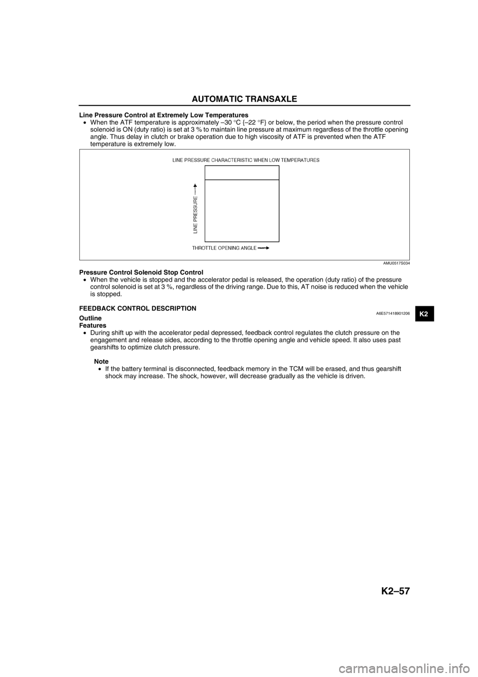
Line Pressure Control at Extremely Low Temperatures
•When the ATF temperature is approximately –30 °C {–22 °F} or below, the period when the pressure control
solenoid is ON (duty ratio) is set at 3 % to maintain line pressure at maximum regardless of the throttle opening
angle. Thus delay in clutch or brake operation due to high viscosity of ATF is prevented when the ATF
temperature is extremely low.
Pressure Control Solenoid Stop Control
•When the vehicle is stopped and the accelerator pedal is released, the operation (duty ratio) of the pressure
control solenoid is set at 3 %, regardless of the driving range. Due to this, AT noise is reduced when the vehicle
is stopped.
End Of Sie
FEEDBACK CONTROL DESCRIPTIONA6E571418901206Outline
Features
•During shift up with the accelerator pedal depressed, feedback control regulates the clutch pressure on the
engagement and release sides, according to the throttle opening angle and vehicle speed. It also uses past
gearshifts to optimize clutch pressure.
Note
•If the battery terminal is disconnected, feedback memory in the TCM will be erased, and thus gearshift
shock may increase. The shock, however, will decrease gradually as the vehicle is driven.
AMU0517S034
Page 474 of 909
AUTOMATIC TRANSAXLE
K2–59
K2
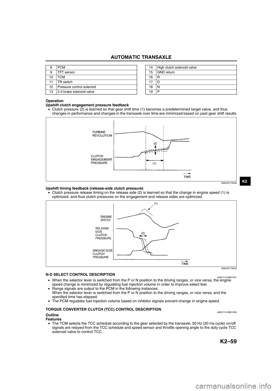
Operation
Upshift clutch engagement pressure feedback
•Clutch pressure (2) is learned so that gear shift time (1) becomes a predetermined target value, and thus
changes in performance and changes in the transaxle over time are minimized based on past gear shift results.
Upshift timing feedback (release-side clutch pressure)
•Clutch pressure release timing on the release side (2) is learned so that the change in engine speed (1) is
optimized, and thus clutch pressures on the engagement and release sides are optimized.
End Of SieN-D SELECT CONTROL DESCRIPTIONA6E571418901207•When the selector lever is switched from the P or N position to the driving ranges, or vice versa, the engine
speed change is minimized by regulating fuel injection volume in order to improve select feel.
•Range signals are output to the PCM in the following instances:
When the selector lever is switched from the P or N position to the driving ranges, or vice versa, and the
specified time has elapsed.
•The PCM regulates fuel injection volume based on inhibitor signals prevent change in engine speed.
End Of Sie
TORQUE CONVERTER CLUTCH (TCC) CONTROL DESCRIPTIONA6E571418901208Outline
Features
•The TCM selects the TCC schedule according to the gear selected by the transaxle. 50 Hz (20 ms cycle) on/off
signals are relayed from the TCC schedule and speed sensor and throttle opening angle to the duty cycle TCC
solenoid valve to control TCC.
8PCM
9 TFT sensor
10 TCM
11 TR switch
12 Pressure control solenoid
13 2-4 brake solenoid valve14 High clutch solenoid valve
15 GND return
16 R
17 D
18 N
19 P
AMU0517S038
AMU0517S039