clutch MAZDA 6 2002 Suplement Owners Manual
[x] Cancel search | Manufacturer: MAZDA, Model Year: 2002, Model line: 6, Model: MAZDA 6 2002Pages: 909, PDF Size: 17.16 MB
Page 490 of 909
AUTOMATIC TRANSAXLE
K2–75
K2
Time Lag Test
1. Perform mechanical system test preparation. (See K2–72 Mechanical System Test Preparation.)
2. Start the engine.
3. Warm up the engine until the ATF temperature reaches 60—70°C {140—158°F}. Shift the selector lever from N
position to D range.
4. Use a stopwatch to measure the time it takes from shifting until engagement is felt. Take three measurements
for each test and average the results using the following formula.
Formula
Average time lag = (Time 1 + Time 2 + Time 3) / 3
5. Perform the test for the following shifts in the same manner.
•N position → P position
Time lag
N → D range ... approx. 0.5—1.0 second
N → R position ... approx. 0.6— 1.0 second
Evaluation of time lag test
End Of SieROAD TESTA6E571401030210Road Test Preparation
1. Inspect the engine coolant. (See Section E.)
2. Inspect the engine oil. (See D–8 ENGINE OIL INSPECTION.)
3. Inspect the ATF levels. (See K2–78 AUTOMATIC TRANSAXLE FLUID (ATF) INSPECTION.)
4. Inspect the idle speed and ignition timing in P position. (See F1–22 IDLE SPEED INSPECTION (4WD).)
5. Bring up the engine and transaxle to normal operating temperature.
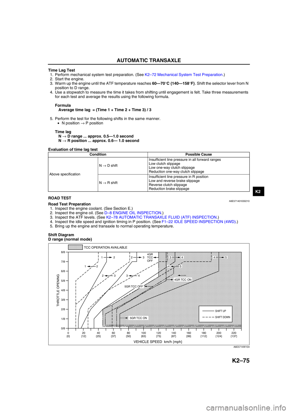
Shift Diagram
D range (normal mode)
Condition Possible Cause
Above specificationN → D shiftInsufficient line pressure in all forward ranges
Low clutch slippage
Low one-way clutch slippage
Reduction one-way clutch slippage
N → R shiftInsufficient line pressure in R position
Low and reverse brake slippage
Reverse clutch slippage
Reduction brake slippage
0/8 1/8
2/8
3/8
4/8
5/8
6/8
7/8
8/8
TCC OPERATION AVAILABLE
VEHICLE SPEED km/h {mph}
THROTTLE OPENING
SHIFT UP
4GR
TCC
OFF
SHIFT DOWN
0
{0}20
{12}40
{25}60
{37}80
{50}100
{63}120
{75}140
{87}160
{99}180
{112}220
{137} 200
{124} 112 23
2
2 232
34
4534
45
5GR TCC ON
4GR TCC ON
5GR TCC OFF
A6E5714W104
Page 493 of 909

K2–78
AUTOMATIC TRANSAXLE
Evaluation
End Of SieAUTOMATIC TRANSAXLE FLUID (ATF) INSPECTIONA6E571419001201Automatic Transaxle Fluid (ATF) Condition Inspection
1. One way of determining whether the transaxle should be replaced is by noting:
•If the ATF is muddy or varnished.
•If the ATF smells strange or unusual.
ATF Condition
Condition Possible Cause
No 1-2 up- or downshiftStuck shift solenoid C
Stuck shift valve C
Wore 2-4 brake
Trouble intermediate sensor
No 2-3 up- or downshiftStuck shift solenoid A
Stuck shift valve A
Wore high clutch
No 3-4 up- or downshiftStuck shift solenoid B
Stuck shift valve B
Wore 2-4 brake
No 4-5 up- or downshiftStuck shift solenoid A
Stuck shift valve A
Wore direct clutch
Trouble TFT
TCC non operation shiftStuck TCC solenoid valve
Stuck TCC valve
Incorrect shift pointTrouble VSS output signal
Trouble TR switch
Trouble TP signal and engine torque signal
Excessive shift shock slippageStuck pressure control solenoid
Stuck pressure regulator valve
Stuck pressure modifier valve
Stuck accumulator valve A, B, or C
Stuck 2-4 brake solenoid valve
Stuck high clutch solenoid valve
Stuck low clutch accumulator
Stuck 2-4 brake accumlator
Stuck high clutch accumlator
Stuck direct clutch accumlator
Stuck reduction accumlator
Trouble VSS
No Engine braking effect Wore reduction brake band
Stuck reduction reducing valve
Stuck reduction timing valve
Stuck reduction timing solenoid valve
Condition Possible cause
Clear dark red Normal—
Light red (pink) Contaminated with water•Broken oil cooler inside of radiator
•Poor filler tube installation:
Problem could be occurring to parts inside the
transaxle by water contamination. If necessary,
exchange transaxle.
Reddish
brownHas burnt smell and metal
specs are foundDeteriorated ATFDefect powertrain components inside of transaxle:
Specks cause wide range of problems by plugging up
in oil pipe, control valve body and oil cooler in radiator.
•When large amount of metal specks are found.
Exchange transaxle if necessary.
•Implement flushing operation as there is a
possibility to have specks plugging up oil pipe and/
or oil cooler inside of radiator.
Has no burnt smell Normal•Discoloration by oxidation
Page 494 of 909
AUTOMATIC TRANSAXLE
K2–79
K2
Automatic Transaxle Fluid (ATF) Level Inspection
Caution
•The ATF amount varies according to ATF's temperature. Therefore, when checking the ATF level or
replacing the ATF, use a thermometer to measure the temperature then adjust the ATF amount to
the specified level according to the specified temperature.
1. Park the vehicle on level ground.
2. Apply the parking brake and position wheel chocks securely to prevent the vehicle from rolling.
3. Adjust the length of the thermistor probe measure to the measure same as the dipstick and hold the probe with
a paper holder.
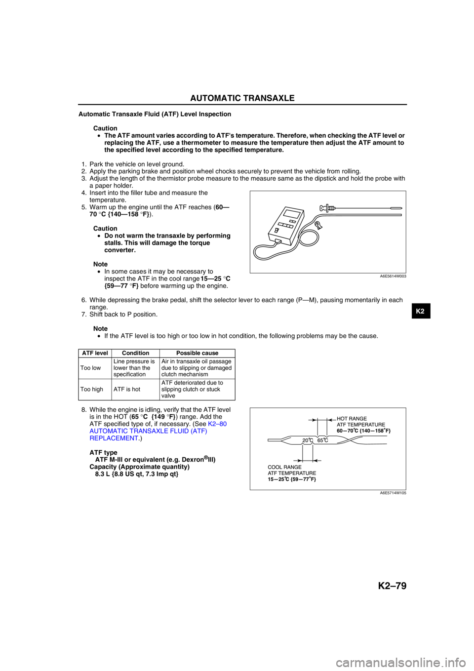
4. Insert into the filler tube and measure the
temperature.
5. Warm up the engine until the ATF reaches (60—
70 °C {140—158 °F}).
Caution
•Do not warm the transaxle by performing
stalls. This will damage the torque
converter.
Note
•In some cases it may be necessary to
inspect the ATF in the cool range 15—25 °C
{59—77 °F} before warming up the engine.
6. While depressing the brake pedal, shift the selector lever to each range (P—M), pausing momentarily in each
range.
7. Shift back to P position.
Note
•If the ATF level is too high or too low in hot condition, the following problems may be the cause.
8. While the engine is idling, verify that the ATF level
is in the HOT (65 °C {149 °F}) range. Add the
ATF specified type of, if necessary. (See K2–80
AUTOMATIC TRANSAXLE FLUID (ATF)
REPLACEMENT.)
ATF type
ATF M-III or equivalent (e.g. Dexron
®III)
Capacity (Approximate quantity)
8.3 L {8.8 US qt, 7.3 Imp qt}
End Of Sie
ATF level Condition Possible cause
Too lowLine pressure is
lower than the
specificationAir in transaxle oil passage
due to slipping or damaged
clutch mechanism
Too high ATF is hotATF deteriorated due to
slipping clutch or stuck
valve
A6E5614W003
A6E5714W105
Page 503 of 909
K2–88
AUTOMATIC TRANSAXLE
SOLENOID VALVE INSPECTIONA6E571421280202Resistance Inspection (On-Vehicle)
1. Disconnect the negative battery cable.
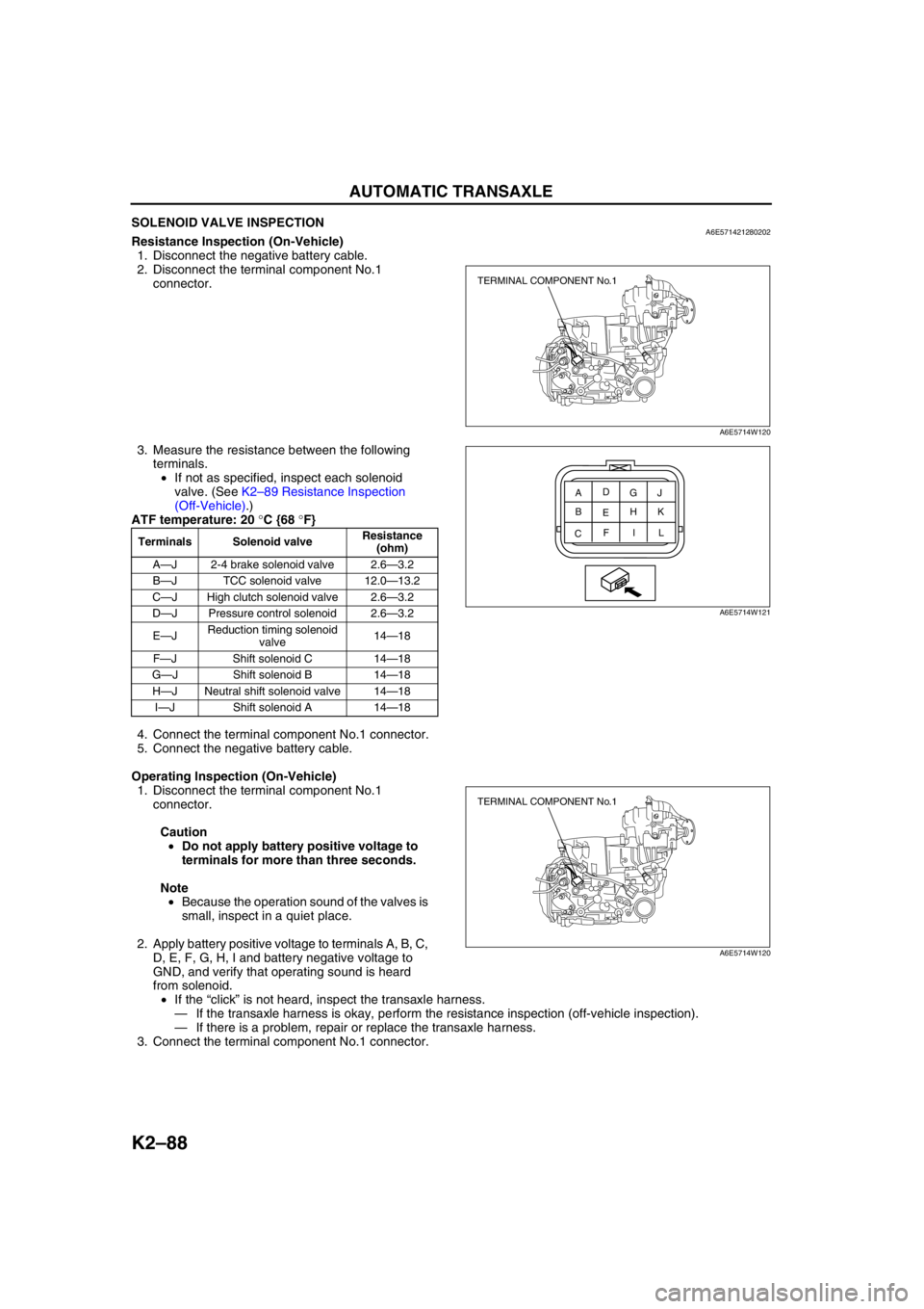
2. Disconnect the terminal component No.1
connector.
3. Measure the resistance between the following
terminals.
•If not as specified, inspect each solenoid
valve. (See K2–89 Resistance Inspection
(Off-Vehicle).)
ATF temperature: 20 °C {68 °F}
4. Connect the terminal component No.1 connector.
5. Connect the negative battery cable.
Operating Inspection (On-Vehicle)
1. Disconnect the terminal component No.1
connector.
Caution
•Do not apply battery positive voltage to
terminals for more than three seconds.
Note
•Because the operation sound of the valves is
small, inspect in a quiet place.
2. Apply battery positive voltage to terminals A, B, C,
D, E, F, G, H, I and battery negative voltage to
GND, and verify that operating sound is heard
from solenoid.
•If the “click” is not heard, inspect the transaxle harness.
—If the transaxle harness is okay, perform the resistance inspection (off-vehicle inspection).
—If there is a problem, repair or replace the transaxle harness.
3. Connect the terminal component No.1 connector.
Terminals Solenoid valveResistance
(ohm)
A—J 2-4 brake solenoid valve 2.6—3.2
B—J TCC solenoid valve 12.0—13.2
C—J High clutch solenoid valve 2.6—3.2
D—J Pressure control solenoid 2.6—3.2
E—JReduction timing solenoid
valve14—18
F—J Shift solenoid C 14—18
G—J Shift solenoid B 14—18
H—J Neutral shift solenoid valve 14—18
I—J Shift solenoid A 14—18
TERMINAL COMPONENT No.1
A6E5714W120
A
CEG
BD
FH
IJ
K
L
A6E5714W121
TERMINAL COMPONENT No.1
A6E5714W120
Page 504 of 909
AUTOMATIC TRANSAXLE
K2–89
K2
Resistance Inspection (Off-Vehicle)
1. Remove each solenoid valve. (See K2–90 SOLENOID VALVE REMOVAL/INSTALLATION.)
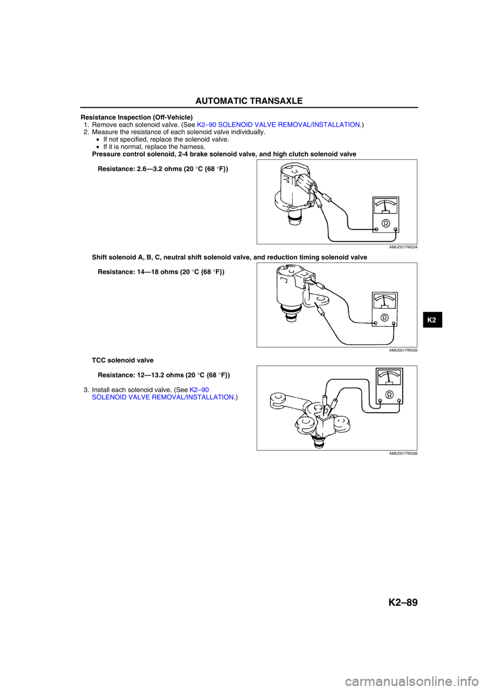
2. Measure the resistance of each solenoid valve individually.
•If not specified, replace the solenoid valve.
•If it is normal, replace the harness.
Pressure control solenoid, 2-4 brake solenoid valve, and high clutch solenoid valve
Resistance: 2.6—3.2 ohms (20 °C {68 °F})
Shift solenoid A, B, C, neutral shift solenoid valve, and reduction timing solenoid valve
Resistance: 14—18 ohms (20 °C {68 °F})
TCC solenoid valve
Resistance: 12—13.2 ohms (20 °C {68 °F})
3. Install each solenoid valve. (See K2–90
SOLENOID VALVE REMOVAL/INSTALLATION.)
End Of Sie
AMU0517W034
AMU0517W035
AMU0517W036
Page 505 of 909
K2–90
AUTOMATIC TRANSAXLE
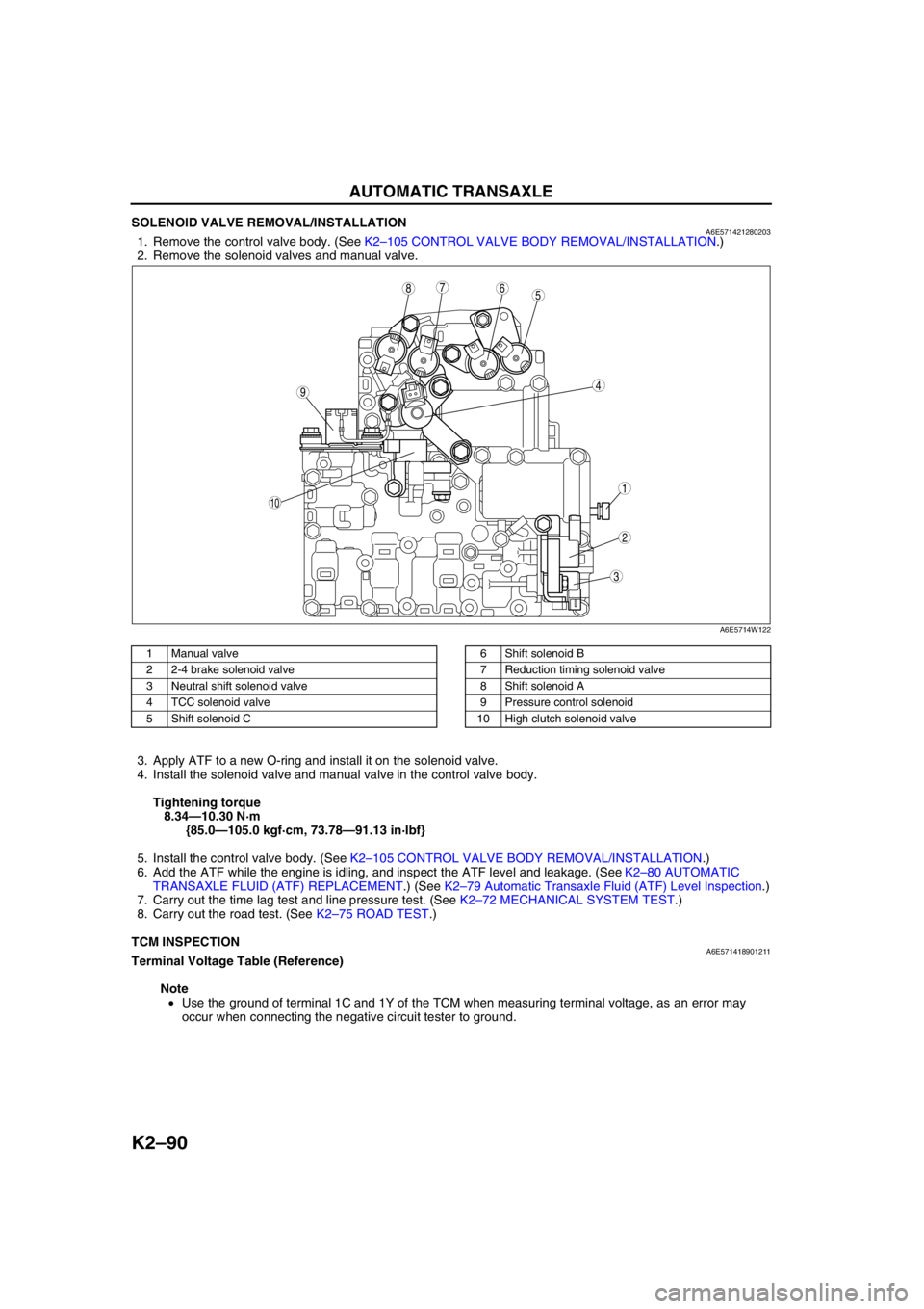
SOLENOID VALVE REMOVAL/INSTALLATIONA6E5714212802031. Remove the control valve body. (See K2–105 CONTROL VALVE BODY REMOVAL/INSTALLATION.)
2. Remove the solenoid valves and manual valve.
.
3. Apply ATF to a new O-ring and install it on the solenoid valve.
4. Install the solenoid valve and manual valve in the control valve body.
Tightening torque
8.34—10.30 N·m
{85.0—105.0 kgf·cm, 73.78—91.13 in·lbf}
5. Install the control valve body. (See K2–105 CONTROL VALVE BODY REMOVAL/INSTALLATION.)
6. Add the ATF while the engine is idling, and inspect the ATF level and leakage. (See K2–80 AUTOMATIC
TRANSAXLE FLUID (ATF) REPLACEMENT.) (See K2–79 Automatic Transaxle Fluid (ATF) Level Inspection.)
7. Carry out the time lag test and line pressure test. (See K2–72 MECHANICAL SYSTEM TEST.)
8. Carry out the road test. (See K2–75 ROAD TEST.)
End Of Sie
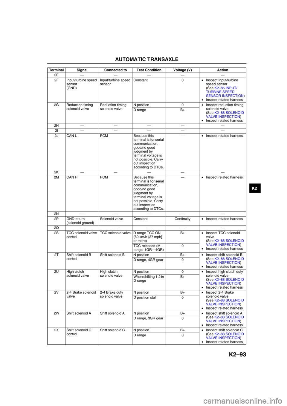
TCM INSPECTIONA6E571418901211Terminal Voltage Table (Reference)
Note
•Use the ground of terminal 1C and 1Y of the TCM when measuring terminal voltage, as an error may
occur when connecting the negative circuit tester to ground.
5
44
3
10
687
9
1
2
A6E5714W122
1 Manual valve
2 2-4 brake solenoid valve
3 Neutral shift solenoid valve
4 TCC solenoid valve
5 Shift solenoid C6 Shift solenoid B
7 Reduction timing solenoid valve
8 Shift solenoid A
9 Pressure control solenoid
10 High clutch solenoid valve
Page 508 of 909
AUTOMATIC TRANSAXLE
K2–93
K2
2E———— —
2F Input/turbine speed
sensor
(GND)Input/turbine speed
sensorConstant 0•Inspect Input/turbine
speed sensor
(See K2–85 INPUT/
TURBINE SPEED
SENSOR INSPECTION)
•Inspect related harness
2G Reduction timing
solenoid valveReduction timing
solenoid valveN position 0•Inspect reduction timing
solenoid valve
(See K2–88 SOLENOID
VALVE INSPECTION)
•Inspect related harness D range B+
2H———— —
2I———— —
2J CAN L PCM Because this
terminal is for serial
communication,
good/no good
judgment by
terminal voltage is
not possible. Carry
out inspection
according to DTCs.—•Inspect related harness
2K———— —
2M CAN H PCM Because this
terminal is for serial
communication,
good/no good
judgment by
terminal voltage is
not possible. Carry
out inspection
according to DTCs.—•Inspect related harness
2N———— —
2P GND return
(solenoid ground)Solenoid valve Constant Continuity•Inspect related harness
2Q———— —
2S TCC solenoid valve
controlTCC solenoid valve D range TCC ON
(60 km/h {37 mph}
or more)B+•Inspect TCC solenoid
valve
(See K2–88 SOLENOID
VALVE INSPECTION)
•Inspect related harness TCC released (M
range, 1GR—4GR)0
2T Shift solenoid B
controlShift solenoid B N position B+•Inspect shift solenoid B
(See K2–88 SOLENOID
VALVE INSPECTION)
•Inspect related harness D range, 4GR gear 0
2U High clutch
solenoid valveHigh clutch
solenoid valveN position 0•Inspect high clutch duty
solenoid valve
(See K2–88 SOLENOID
VALVE INSPECTION)
•Inspect related harness When shifting 1-2 in
D rangeB+
2V 2-4 Brake solenoid
valve2-4 Brake duty
solenoid valveN position B+•Inspect 2-4 Brake
solenoid valve
(See K2–88 SOLENOID
VALVE INSPECTION)
•Inspect related harness D position stall 0
2W Shift solenoid A Shift solenoid A N position B+•Inspect shift solenoid A
(See K2–88 SOLENOID
VALVE INSPECTION)
•Inspect related harness D range, 3GR gear 0
2X Shift solenoid C
controlShift solenoid C N position B+•Inspect shift solenoid C
(See K2–88 SOLENOID
VALVE INSPECTION)
•Inspect related harness D range 0 Terminal Signal Connected to Test Condition Voltage (V) Action
Page 510 of 909
AUTOMATIC TRANSAXLE
K2–95
K2
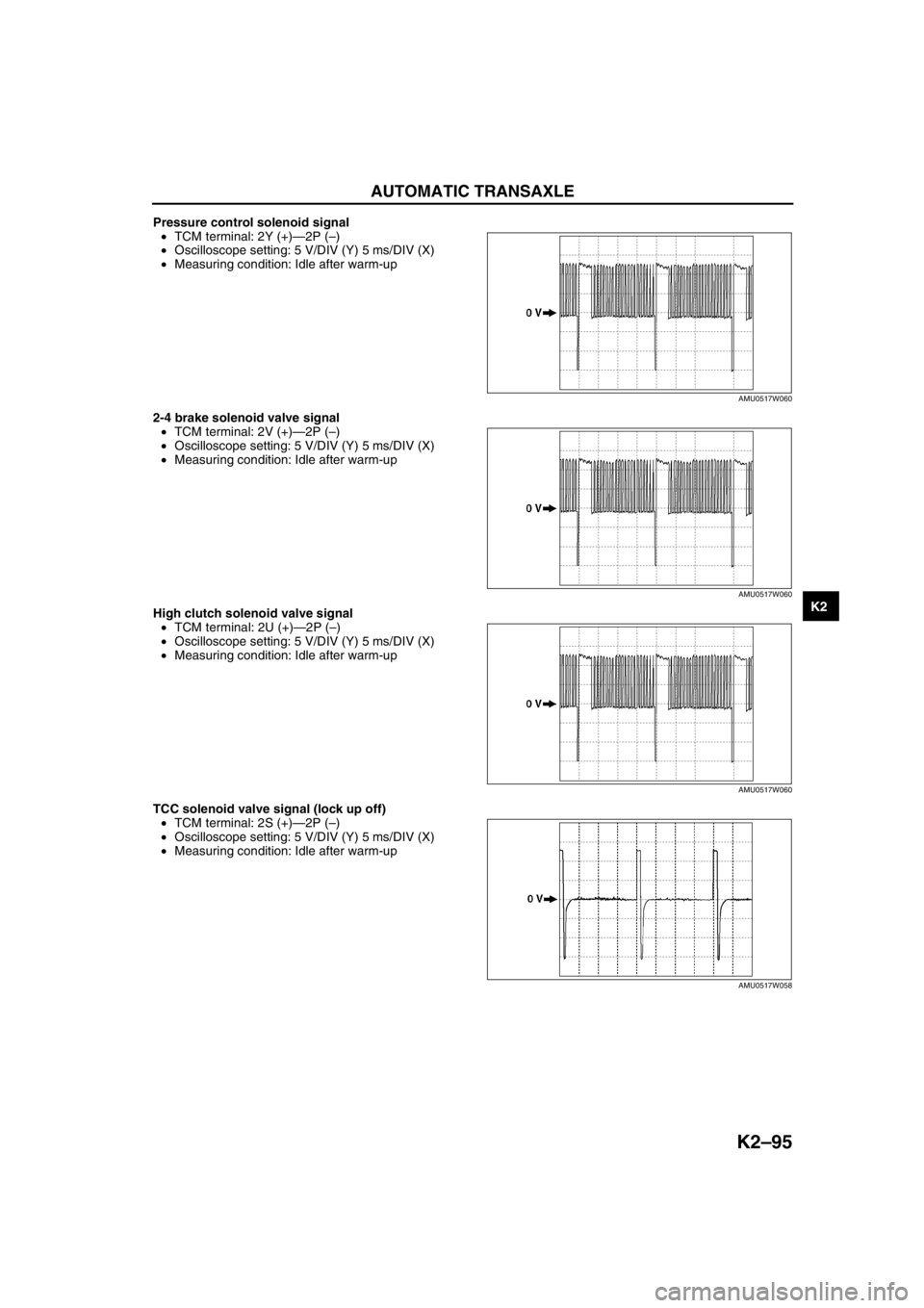
Pressure control solenoid signal
•TCM terminal: 2Y (+)—2P (–)
•Oscilloscope setting: 5 V/DIV (Y) 5 ms/DIV (X)
•Measuring condition: Idle after warm-up
2-4 brake solenoid valve signal
•TCM terminal: 2V (+)—2P (–)
•Oscilloscope setting: 5 V/DIV (Y) 5 ms/DIV (X)
•Measuring condition: Idle after warm-up
High clutch solenoid valve signal
•TCM terminal: 2U (+)—2P (–)
•Oscilloscope setting: 5 V/DIV (Y) 5 ms/DIV (X)
•Measuring condition: Idle after warm-up
TCC solenoid valve signal (lock up off)
•TCM terminal: 2S (+)—2P (–)
•Oscilloscope setting: 5 V/DIV (Y) 5 ms/DIV (X)
•Measuring condition: Idle after warm-up
AMU0517W060
AMU0517W060
AMU0517W060
AMU0517W058
Page 514 of 909
AUTOMATIC TRANSAXLE
K2–99
K2
AUTOMATIC TRANSAXLE AND TRANSFER REMOVAL/INSTALLATIONA6E5714190902011. Disconnect the negative battery cable.
2. Remove the battery and battery tray.
3. Remove the aircleaner component. (See Sectin F.)
4. Remove the front tires and splash shield.
5. Remove the under cover.
6. Separate the steering shaft and steering hose. (See N–13 STEERING GEAR AND LINKAGE (4WD)
REMOVAL/INSTALLATION.)
7. Remove the front auto leveling sensor. (See Section T.)
8. Drain the ATF. (See K2–80 AUTOMATIC TRANSAXLE FLUID (ATF) REPLACEMENT.)
Warning
•Improperly jacking a transaxle is dangerous. It can slip off the jack and may cause serious injury.
Caution
•To prevent the torque converter and transaxle from separating, remove the transaxle without
tilting it toward the torque converter.
9. Remove in the order shown in the figure.
10. Install in the reverse order of removal.
11. Adjust the headlight zeroset. (See Section T.)
12. Add ATF to the specified level. (See K2–80 AUTOMATIC TRANSAXLE FLUID (ATF) REPLACEMENT.)
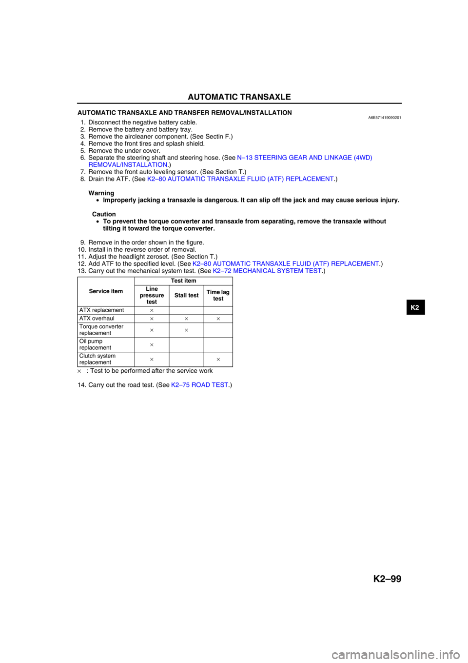
13. Carry out the mechanical system test. (See K2–72 MECHANICAL SYSTEM TEST.)
×: Test to be performed after the service work
14. Carry out the road test. (See K2–75 ROAD TEST.)
Service itemTest item
Line
pressure
testStall testTime lag
test
ATX replacement×
ATX overhaul×××
Torque converter
replacement××
Oil pump
replacement×
Clutch system
replacement××
Page 541 of 909
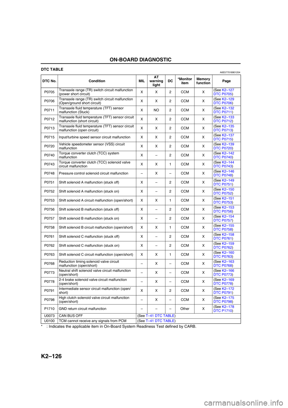
K2–126
ON-BOARD DIAGNOSTIC
DTC TABLEA6E577018901204
* : Indicates the applicable item in On-Board System Readiness Test defined by CARB.
End Of Sie
DTC No. Condition MILAT
warning
lightDC*Monitor
itemMemory
functionPage
P0705Transaxle range (TR) switch circuit malfunction
(power short circuit)XX2CCM X(See K2–127
DTC P0705)
P0706Transaxle range (TR) switch circuit malfunction
(Open/ground short circuit)XX2CCM X(See K2–129
DTC P0706)
P0711Transaxle fluid temperature (TFT) sensor
malfunction (Stuck)XNO2CCM X(See K2–132
DTC P0711)
P0712Transaxle fluid temperature (TFT) sensor circuit
malfunction (short circuit)XX2CCM X(See K2–133
DTC P0712)
P0713Transaxle fluid temperature (TFT) sensor circuit
malfunction (open circuit)XX2CCM X(See K2–135
DTC P0713)
P0715 Input/turbine speed sensor circuit malfunction X X 2 CCM X(See K2–137
DTC P0715)
P0720Vehicle speedometer sensor (VSS) circuit
malfunctionXX2CCM X(See K2–139
DTC P0720)
P0740Torque converter clutch (TCC) system
malfunctionX–2CCM X(See K2–142
DTC P0740)
P0743Torque converter clutch (TCC) solenoid valve
circuit malfunctionXX1CCM X(See K2–144
DTC P0743)
P0748 Pressure control solenoid circuit malfunction–X–CCM X(See K2–146
DTC P0748)
P0751 Shift solenoid A malfunction (stuck off) X–2CCM X(See K2–149
DTC P0751)
P0752 Shift solenoid A malfunction (stuck on) X–2CCM X(See K2–150
DTC P0752)
P0753 Shift solenoid A circuit malfunction (open/short) X X 1 CCM X(See K2–151
DTC P0753)
P0756 Shift solenoid B malfunction (stuck off) X–2CCM X(See K2–153
DTC P0756)
P0757 Shift solenoid B malfunction (stuck on) X–2CCM X(See K2–154
DTC P0757)
P0758 Shift solenoid B circuit malfunction (open/short) X X 1 CCM X(See K2–155
DTC P0758)
P0761 Shift solenoid C malfunction (stuck off) X–2CCM X(See K2–158
DTC P0761)
P0762 Shift solenoid C malfunction (stuck on) X–2CCM X(See K2–159
DTC P0762)
P0763 Shift solenoid C circuit malfunction (open/short) X X 1 CCM X(See K2–160
DTC P0763)
P0768Reduction timing solenoid valve circuit
malfunction (open/short)–X–CCM X(See K2–163
DTC P0768)
P0773Neutral shift solenoid valve circuit malfunction
(open/short)–X–CCM X(See K2–166
DTC P0773)
P07782-4 brake solenoid valve circuit malfunction
(open/short)–X–CCM X(See K2–169
DTC P0778)
P0791Intermediate sensor circuit malfunction (open/
short)XX2CCM X(See K2–172
DTC P0791)
P0798High clutch solenoid valve circuit malfunction
(open/short)–X–CCM X(See K2–175
DTC P0798)
P1710 GND return circuit malfunction–––Other X(See K2–178
DTC P1710)
U0073 CAN BUS OFF (See T–41 DTC TABLE)
U0100 TCM cannot receive any signals from PCM (See T–41 DTC TABLE)