heater MAZDA 6 2002 Workshop Manual Suplement
[x] Cancel search | Manufacturer: MAZDA, Model Year: 2002, Model line: 6, Model: MAZDA 6 2002Pages: 909, PDF Size: 17.16 MB
Page 1 of 909
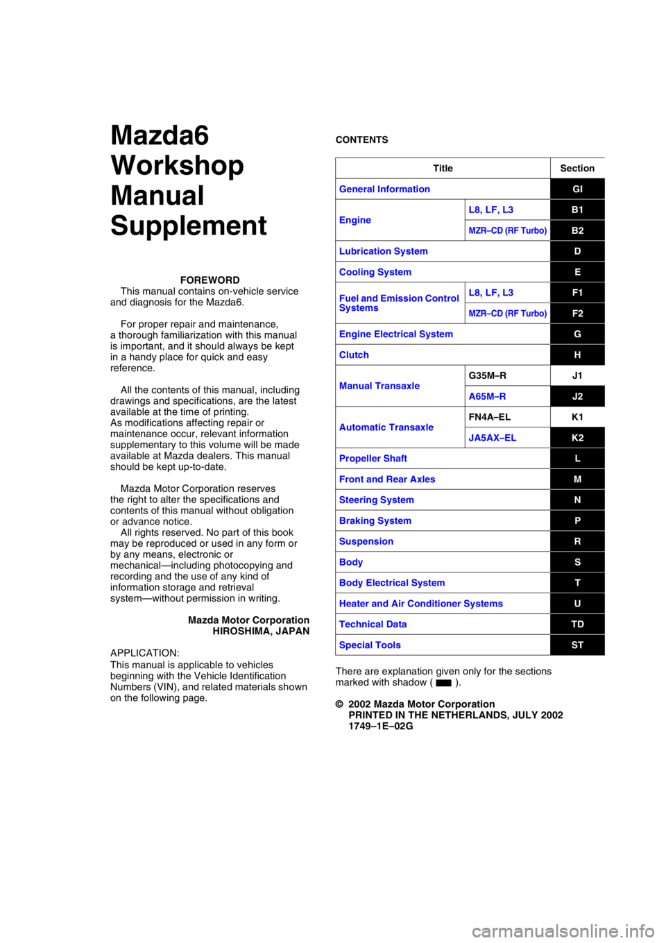
CONTENTSMazda6
Workshop
Manual
Supplement
FOREWORD
This manual contains on-vehicle service
and diagnosis for the Mazda6.
For proper repair and maintenance,
a thorough familiarization with this manual
is important, and it should always be kept
in a handy place for quick and easy
reference.
All the contents of this manual, including
drawings and specifications, are the latest
available at the time of printing.
As modifications affecting repair or
maintenance occur, relevant information
supplementary to this volume will be made
available at Mazda dealers. This manual
should be kept up-to-date.
Mazda Motor Corporation reserves
the right to alter the specifications and
contents of this manual without obligation
or advance notice.
All rights reserved. No part of this book
may be reproduced or used in any form or
by any means, electronic or
mechanical—including photocopying and
recording and the use of any kind of
information storage and retrieval
system—without permission in writing.
Mazda Motor Corporation
HIROSHIMA, JAPAN
APPLICATION:
This manual is applicable to vehicles
beginning with the Vehicle Identification
Numbers (VIN), and related materials shown
on the following page.There are explanation given only for the sections
marked with shadow ( ).
© 2002 Mazda Motor Corporation
PRINTED IN THE NETHERLANDS, JULY 2002
1749–1E–02G
Title Section
General Information
GI
EngineL8, LF, L3
B1
MZR–CD (RF Turbo)B2
Lubrication System
D
Cooling System
E
Fuel and Emission Control
SystemsL8, LF, L3
F1
MZR–CD (RF Turbo)F2
Engine Electrical System
G
Clutch
H
Manual TransaxleG35M
–RJ1
A65M
–RJ2
Automatic TransaxleFN4A
–ELK1
JA5AX
–ELK2
Propeller Shaft
L
Front and Rear Axles
M
Steering System
N
Braking System
P
Suspension
R
Body
S
Body Electrical System
T
Heater and Air Conditioner Systems
U
Technical Data
TD
Special Tools
ST
Page 8 of 909

NEW STANDARDS
GI–5
GINEW STANDARDS TABLEA6E202800020201•The following is a comparison of the previous standard and the new standard.
NEW STANDARDS
New Standard Previous Standard
Remark
Abbrevi-
ationNameAbbrevi-
ationName
AP Accelerator Pedal—Accelerator Pedal
ACL Air Cleaner—Air Cleaner
A/C Air Conditioning—Air Conditioning
BARO Barometric Pressure—Atmospheric Pressure
B+ Battery Positive VoltageV
BBattery Voltage
—Brake Switch—Stoplight Switch
—Calibration Resistor—Corrected Resistance #6
CMP sensor Camshaft Position Sensor—Crank Angle Sensor
CAC Charge Air Cooler—Intercooler
CLS Closed Loop System—Feedback System
CTP Closed Throttle Position—Fully Closed
—Closed Throttle Position Switch—Idle Switch
CPP Clutch Pedal Position—Clutch Position
CIS Continuous Fuel Injection System EGI Electronic Gasoline Injection System
CS sensor Control Sleeve Sensor CSP sensor Control Sleeve Position Sensor #6
CKP sensor Crankshaft Position Sensor—Crank Angle Sensor 2
DLC Data Link Connector—Diagnosis Connector
DTM Diagnostic Test Mode—Test Mode #1
DTC Diagnostic Trouble Code—Service Code(s)
DI Distributor Ignition—Spark Ignition
DLI Distributorless Ignition—Direct Ignition
EI Electronic Ignition—Electronic Spark Ignition #2
ECT Engine Coolant Temperature—Water Thermo
EM Engine Modification—Engine Modification
—Engine Speed Input Signal—Engine RPM Signal
EVAP Evaporative Emission—Evaporative Emission
EGR Exhaust Gas Recirculation—Exhaust Gas Recirculation
FC Fan Control—Fan Control
FF Flexible Fuel—Flexible Fuel
4GR Fourth Gear—Overdrive
—Fuel Pump Relay—Circuit Opening Relay #3
FSO
solenoidFuel Shut Off Solenoid FCV Fuel Cut Valve #6
GEN Generator—Alternator
GND Ground—Ground/Earth
HO2S Heated Oxygen Sensor—Oxygen Sensor With heater
IAC Idle Air Control—Idle Speed Control
—IDM Relay—Spill Valve Relay #6
—Incorrect Gear Ratio——
—Injection Pump FIP Fuel Injection Pump #6
—Input/Turbine Speed Sensor—Pulse Generator
IAT Intake Air Temperature—Intake Air Thermo
KS Knock Sensor—Knock Sensor
MIL Malfunction Indicator Lamp—Malfunction Indicator Light
MAP Manifold Absolute Pressure—Intake Air Pressure
MAF sensor Mass Air Flow Sensor—Airflow Sensor
MFI Multiport Fuel Injection—Multiport Fuel Injection
OBD On Board Diagnostic—Diagnosis/Self Diagnosis
Page 26 of 909
B1–4
OUTLINE, ENGINE
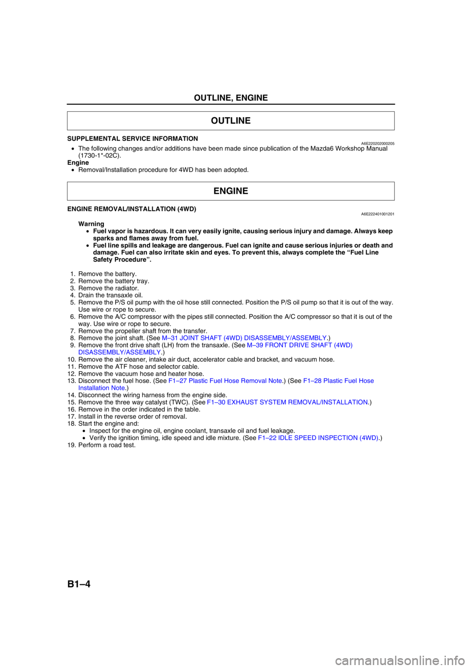
SUPPLEMENTAL SERVICE INFORMATIONA6E220202000205•The following changes and/or additions have been made since publication of the Mazda6 Workshop Manual
(1730-1*-02C).
Engine
•Removal/Installation procedure for 4WD has been adopted.
End Of Sie
ENGINE REMOVAL/INSTALLATION (4WD)A6E222401001201
Warning
•Fuel vapor is hazardous. It can very easily ignite, causing serious injury and damage. Always keep
sparks and flames away from fuel.
•Fuel line spills and leakage are dangerous. Fuel can ignite and cause serious injuries or death and
damage. Fuel can also irritate skin and eyes. To prevent this, always complete the “Fuel Line
Safety Procedure”.
1. Remove the battery.
2. Remove the battery tray.
3. Remove the radiator.
4. Drain the transaxle oil.
5. Remove the P/S oil pump with the oil hose still connected. Position the P/S oil pump so that it is out of the way.
Use wire or rope to secure.
6. Remove the A/C compressor with the pipes still connected. Position the A/C compressor so that it is out of the
way. Use wire or rope to secure.
7. Remove the propeller shaft from the transfer.
8. Remove the joint shaft. (See M–31 JOINT SHAFT (4WD) DISASSEMBLY/ASSEMBLY.)
9. Remove the front drive shaft (LH) from the transaxle. (See M–39 FRONT DRIVE SHAFT (4WD)
DISASSEMBLY/ASSEMBLY.)
10. Remove the air cleaner, intake air duct, accelerator cable and bracket, and vacuum hose.
11. Remove the ATF hose and selector cable.
12. Remove the vacuum hose and heater hose.
13. Disconnect the fuel hose. (See F1–27 Plastic Fuel Hose Removal Note.) (See F1–28 Plastic Fuel Hose
Installation Note.)
14. Disconnect the wiring harness from the engine side.
15. Remove the three way catalyst (TWC). (See F1–30 EXHAUST SYSTEM REMOVAL/INSTALLATION.)
16. Remove in the order indicated in the table.
17. Install in the reverse order of removal.
18. Start the engine and:
•Inspect for the engine oil, engine coolant, transaxle oil and fuel leakage.
•Verify the ignition timing, idle speed and idle mixture. (See F1–22 IDLE SPEED INSPECTION (4WD).)
19. Perform a road test.
OUTLINE
ENGINE
Page 58 of 909
ENGINE
B2–27
B2
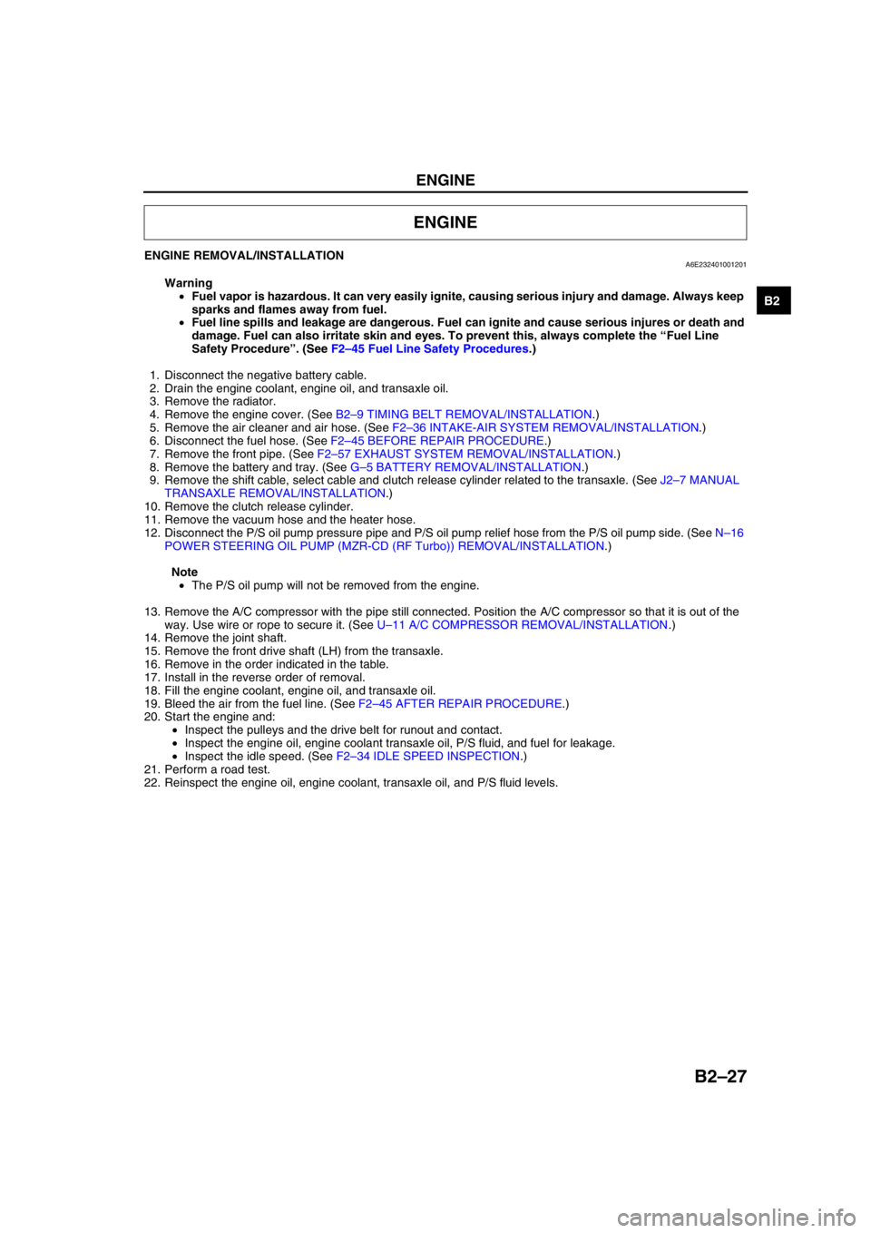
ENGINE REMOVAL/INSTALLATIONA6E232401001201
Warning
•Fuel vapor is hazardous. It can very easily ignite, causing serious injury and damage. Always keep
sparks and flames away from fuel.
•Fuel line spills and leakage are dangerous. Fuel can ignite and cause serious injures or death and
damage. Fuel can also irritate skin and eyes. To prevent this, always complete the “Fuel Line
Safety Procedure”. (See F2–45 Fuel Line Safety Procedures.)
1. Disconnect the negative battery cable.
2. Drain the engine coolant, engine oil, and transaxle oil.
3. Remove the radiator.
4. Remove the engine cover. (See B2–9 TIMING BELT REMOVAL/INSTALLATION.)
5. Remove the air cleaner and air hose. (See F2–36 INTAKE-AIR SYSTEM REMOVAL/INSTALLATION.)
6. Disconnect the fuel hose. (See F2–45 BEFORE REPAIR PROCEDURE.)
7. Remove the front pipe. (See F2–57 EXHAUST SYSTEM REMOVAL/INSTALLATION.)
8. Remove the battery and tray. (See G–5 BATTERY REMOVAL/INSTALLATION.)
9. Remove the shift cable, select cable and clutch release cylinder related to the transaxle. (See J2–7 MANUAL
TRANSAXLE REMOVAL/INSTALLATION.)
10. Remove the clutch release cylinder.
11. Remove the vacuum hose and the heater hose.
12. Disconnect the P/S oil pump pressure pipe and P/S oil pump relief hose from the P/S oil pump side. (See N–16
POWER STEERING OIL PUMP (MZR-CD (RF Turbo)) REMOVAL/INSTALLATION.)
Note
•The P/S oil pump will not be removed from the engine.
13. Remove the A/C compressor with the pipe still connected. Position the A/C compressor so that it is out of the
way. Use wire or rope to secure it. (See U–11 A/C COMPRESSOR REMOVAL/INSTALLATION.)
14. Remove the joint shaft.
15. Remove the front drive shaft (LH) from the transaxle.
16. Remove in the order indicated in the table.
17. Install in the reverse order of removal.
18. Fill the engine coolant, engine oil, and transaxle oil.
19. Bleed the air from the fuel line. (See F2–45 AFTER REPAIR PROCEDURE.)
20. Start the engine and:
•Inspect the pulleys and the drive belt for runout and contact.
•Inspect the engine oil, engine coolant transaxle oil, P/S fluid, and fuel for leakage.
•Inspect the idle speed. (See F2–34 IDLE SPEED INSPECTION.)
21. Perform a road test.
22. Reinspect the engine oil, engine coolant, transaxle oil, and P/S fluid levels.
ENGINE
Page 79 of 909
E–4
COOLING SYSTEM
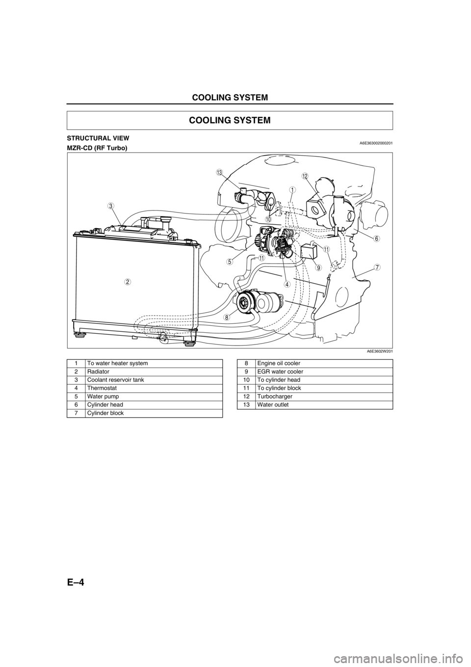
STRUCTURAL VIEWA6E363002000201MZR-CD (RF Turbo)
.
End Of Sie
COOLING SYSTEM
8
75
4
3
1
2
6
10
11
11
9
1312
A6E3602W201
1 To water heater system
2 Radiator
3 Coolant reservoir tank
4Thermostat
5 Water pump
6 Cylinder head
7 Cylinder block8 Engine oil cooler
9EGR water cooler
10 To cylinder head
11 To cylinder block
12 Turbocharger
13 Water outlet
Page 80 of 909
COOLING SYSTEM
E–5
E
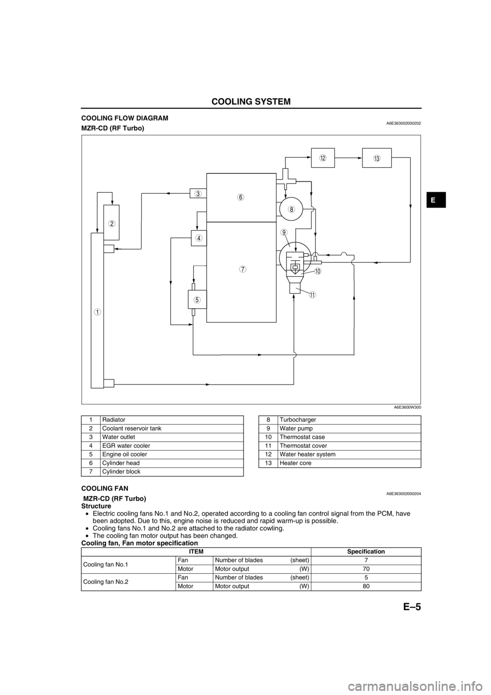
COOLING FLOW DIAGRAMA6E363002000202MZR-CD (RF Turbo)
.
End Of SieCOOLING FANA6E363002000204 MZR-CD (RF Turbo)
Structure
•Electric cooling fans No.1 and No.2, operated according to a cooling fan control signal from the PCM, have
been adopted. Due to this, engine noise is reduced and rapid warm-up is possible.
•Cooling fans No.1 and No.2 are attached to the radiator cowling.
•The cooling fan motor output has been changed.
Cooling fan, Fan motor specification
End Of Sie
9
8
7
5
4
3
1
2
10
13
11
12
6
A6E3600W300
1Radiator
2 Coolant reservoir tank
3 Water outlet
4EGR water cooler
5 Engine oil cooler
6 Cylinder head
7 Cylinder block8 Turbocharger
9 Water pump
10 Thermostat case
11 Thermostat cover
12 Water heater system
13 Heater core
ITEM Specification
Cooling fan No.1Fan Number of blades (sheet) 7
Motor Motor output (W) 70
Cooling fan No.2Fan Number of blades (sheet) 5
Motor Motor output (W) 80
Page 93 of 909

OUTLINE
F1–5
F1
11 Knock sensor
12 CKP sensor
13 CMP sensor
14 Fuel injector No.1
15 Fuel injector No.2
16 Fuel injector No.3
17 Fuel injector No.4
18 IAC valve
19 Oxygen sensor heater (front)
20 Oxygen sensor heater (rear)
21 A/C relay22 Cooling fan relay
23 Cooling fan relay
24 Cooling fan relay
25 TR switch
26 Fuel pump relay
27 Coil
28 Security light
29 Ignition switch
30 Main relay
31 TR switch
32 Starter relay
Page 96 of 909
F1–8
OUTLINE
.
15 Fuel injector No.2
16 Fuel injector No.3
17 Fuel injector No.4
18 IAC valve
19 Oxygen sensor heater (front)
20 Oxygen sensor heater (rear)
21 A/C relay22 Cooling fan relay
23 Cooling fan relay
24 Cooling fan relay
25 Cooling fan relay
26 Fuel pump relay
27 Ignition switch
28 Main relay
1AA
1Q
1Z
1AC
1K
1C1D 4M4R 4N4K 4H4E
4T 4C4U 1AD1B 1A 2AB4X
39
38
37
35
36
33
31
32
40
44
43
41
42
34
29
30
A6E39022004
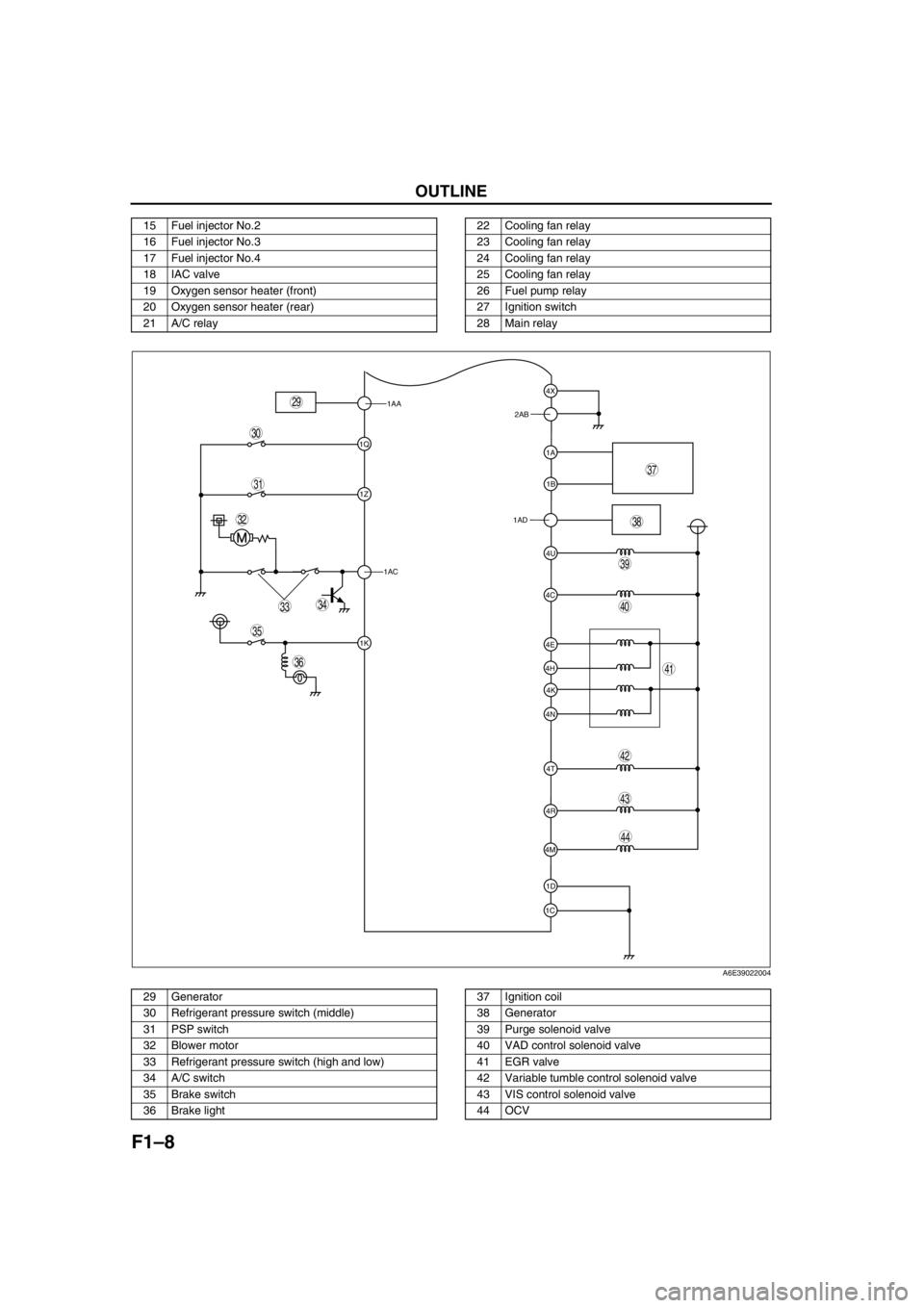
29 Generator
30 Refrigerant pressure switch (middle)
31 PSP switch
32 Blower motor
33 Refrigerant pressure switch (high and low)
34 A/C switch
35 Brake switch
36 Brake light37 Ignition coil
38 Generator
39 Purge solenoid valve
40 VAD control solenoid valve
41 EGR valve
42 Variable tumble control solenoid valve
43 VIS control solenoid valve
44 OCV
Page 103 of 909

CONTROL SYSTEM
F1–15
F1
Output Device
×:Applied
—: Not applied
* : For L3 engine only
End Of Sie
Item SignalMazda6 (GG, GY)
Remark for new model
4WD ATX Unleaded
(RON 90
or above)Current
model
IAC valve IAC×Same as current model
VIC solenoid valve* VIC×—×Same as current model
Variable tumble control
solenoid valveVTCS×Same as current model
Oil control valve (OCV)*Variable valve
timing control×—×Same as current model
Fuel injectorFuel injection
control×Same as current model
Fuel pump relayFuel pump
control×Same as current model
Ignition coil ESA control×Same as current model
EGR valve EGR control×Same as current model
Purge solenoid valve Purge control×Same as current model
BARO factor for Purge control has been
eliminated.
Heated oxygen sensor
heater
(Front, rear)O2S heater
control×Same as current model
Field coil
(Generator terminal D)Generator
control×Same as current model
Cooling fan relayElectric fan
control×Same as current model
A/C relayA/C cut-off
control×Same as current model
Controller area network
(CAN)Information
function×Same as current model
TCM (ATX) information have been
adopted for 4WD ATX model.
Page 106 of 909

F1–18
CONTROL SYSTEM
*1: For MTX model
*2: For 2WD ATX model
*3: For L3 engine
End Of Sie
1 MAF/IAT sensor
2 TP sensor
3 MAP sensor
4 CMP sensor
5 CKP sensor
6 ECT sensor
7 Knock sensor
8 HO2S (front, rear)
9 PSP switch
10 Vehicle speedometer sensor
11
Clutch switch*
1
12
Neutral switch*1
13
TR switch*2
14 Brake switch
15 A/C switch
16 Refrigerant pressure switch
17 Generator (terminal P: generation voltage)
18 Battery
19
VAD control solenoid valve*
3
20 IAC valve
21
VIC solenoid valve*
3
22 Variable tumble control solenoid valve
23
OCV*
3
24 Fuel injector
25 Fuel pump relay
26 Ignition coil
27 Purge solenoid valve
28 EGR valve
29 Oxygen sensor heater (front, rear)
30 A/C relay
31 Cooling fan relay
32 Generator (terminal D: field coil)
33
VAD control*
3
34 IAC
35
VIC*
3
36 VTCS
37
Variable valve timing control*
3
38 Fuel injection control
39 Fuel pump control
40 Electronic spark advance (ESA) control
41 Purge control
42 EGR control
43 Oxygen sensor heater control
44 A/C cut-off control
45 Electrical fan control
46 Generator control