weight MAZDA 6 2002 Workshop Manual Suplement
[x] Cancel search | Manufacturer: MAZDA, Model Year: 2002, Model line: 6, Model: MAZDA 6 2002Pages: 909, PDF Size: 17.16 MB
Page 33 of 909

B2–2
OUTLINE
OUTLINE OF CONSTRUCTIONA6E230202000201•MZR-CD (RF Turbo) engine is newly adopted as Mazda6 (GG, GY).
•The construction of MZR-CD (RF Turbo) engine and operation which were newly adopted for the Mazda6 (GG,
GY) are the same as the current Mazda MPV(LW) MZR-CD (RF Turbo) engine model and current Mazda 323
(BJ) RF Turbo engine model except for the following components. (See Mazda MPV Workshop Manual
Supplement 1737-1*-02C.), (See Mazda 323 Workshop Manual Supplement 1633-10-98G.)
—Engine mount
•The construction and the operation of the engine mount for the new Mazda6 (GG, GY) MZR-CD (RF Turbo)
engine model is the same as the current Mazda6 (GG). (See Mazda6 Training Manual 3359-1*-02C)
End Of Sie
FEATURESA6E230202000202Improved engine performance
•Coated pistons have been adopted.
Reduced engine noise and vibration
•An aluminium alloy oil pan upper block has been adopted.
•An eight counter weight crankshaft has been adopted.
•A crankshaft pulley cover has been adopted.
•An engine cover with insulator has been adopted.
•A pendulum type engine mount has been adopted.
Improved serviceability
•A serpentine type drive belt has been adopted.
•An auto tensioner that automatically adjusts the drive belt tension has been adopted.
Improved design
•An engine cover has been adopted.
End Of Sie
SPECIFICATIONSA6E230202000203
End Of Sie
OUTLINE
ItemSpecifications
New Mazda6 (GG, GY) Current Mazda MPV (LW)
MZR-CD (RF Turbo) MZR-CD (RF Turbo)
TypeDiesel, 4-cycle
Cylinder arrangement and number In-line, 4-cylinder
Combustion chamber Direct injection
Valve system SOHC, belt-driven, 16-valve
Displacement (ml {cc, cu in}) 1,998 {1.998, 122.9}
Bore × stroke (mm {in}) 86.0 × 86.0 {3.39 × 3.39}
Compression ratio 18.4
Compression pressure
(kPa {kgf/cm
2, psi} [rpm])3,500 {35.7, 507.7} [250]
Valve timingINOpen BTDC (°)6
Close ABDC (°)30
EXOpen BBDC (°)41
Close ATDC (°)8
Valve clearance
[engine cold]IN (mm {in}) 0.12 —0.18 {0.005—0.007} (0.15±0.03 {0.006±0.0011})
EX (mm {in}) 0.32—0.38 {0.013—0.014} (0.35±0.03 {0.014±0.0011})
Page 418 of 909

OUTLINE
K2–3
K2
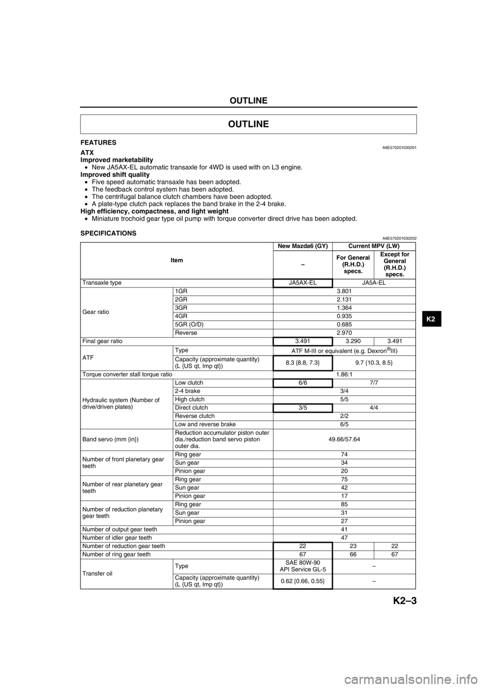
FEATURESA6E570201030201ATX
Improved marketability
•New JA5AX-EL automatic transaxle for 4WD is used with on L3 engine.
Improved shift quality
•Five speed automatic transaxle has been adopted.
•The feedback control system has been adopted.
•The centrifugal balance clutch chambers have been adopted.
•A plate-type clutch pack replaces the band brake in the 2-4 brake.
High efficiency, compactness, and light weight
•Miniature trochoid gear type oil pump with torque converter direct drive has been adopted.
End Of Sie
SPECIFICATIONSA6E570201030202
OUTLINE
ItemNew Mazda6 (GY) Current MPV (LW)
–For General
(R.H.D.)
specs.Except for
General
(R.H.D.)
specs.
Transaxle type JA5AX-EL JA5A-EL
Gear ratio1GR 3.801
2GR 2.131
3GR 1.364
4GR 0.935
5GR (O/D) 0.685
Reverse 2.970
Final gear ratio 3.491 3.290 3.491
ATFType
ATF M-III or equivalent (e.g. Dexron
®III)
Capacity (approximate quantity)
(L {US qt, Imp qt})8.3 {8.8, 7.3} 9.7 {10.3, 8.5}
Torque converter stall torque ratio 1.86:1
Hydraulic system (Number of
drive/driven plates)Low clutch 6/6 7/7
2-4 brake 3/4
High clutch 5/5
Direct clutch 3/5 4/4
Reverse clutch 2/2
Low and reverse brake 6/5
Band servo (mm {in})Reduction accumulator piston outer
dia./reduction band servo piston
outer dia.49.66/57.64
Number of front planetary gear
teethRing gear 74
Sun gear 34
Pinion gear 20
Number of rear planetary gear
teethRing gear 75
Sun gear 42
Pinion gear 17
Number of reduction planetary
gear teethRing gear 85
Sun gear 31
Pinion gear 27
Number of output gear teeth 41
Number of idler gear teeth 47
Number of reduction gear teeth 22 23 22
Number of ring gear teeth 67 66 67
Transfer oilTypeSAE 80W-90
API Service GL-5–
Capacity (approximate quantity)
(L {US qt, Imp qt})0.62 {0.66, 0.55}–
Page 456 of 909

AUTOMATIC TRANSAXLE
K2–41
K2
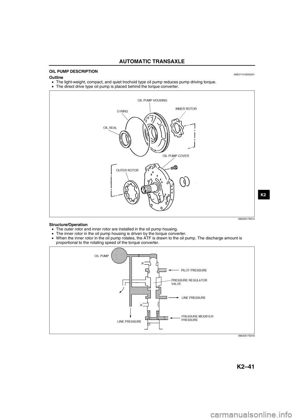
OIL PUMP DESCRIPTIONA6E571419220201Outline
•The light-weight, compact, and quiet trochoid type oil pump reduces pump driving torque.
•The direct drive type oil pump is placed behind the torque converter.
Structure/Operation
•The outer rotor and inner rotor are installed in the oil pump housing.
•The inner rotor in the oil pump housing is driven by the torque converter.
•When the inner rotor in the oil pump rotates, the ATF is drawn to the oil pump. The discharge amount is
proportional to the rotating speed of the torque converter.
End Of Sie
AMU0517S015
AMU0517S016
Page 636 of 909

M–6
REAR DIFFERENTIAL
End Of Sie
REAR DIFFERENTIAL OUTLINEA6E631927100201Features
Size and weight reduction
•A rear differential with an integrated coupling component has been adopted.
•An aluminum differential carrier has been adopted.
End Of Sie
CROSS-SECTIONAL VIEWA6E631927100202
.
End Of Sie
REAR DIFFERENTIAL
12
A6E63192001
1 Coupling component section2 Rear differential section
Page 639 of 909

ELECTRONIC 4WD CONTROL SYSTEM
M–9
M
End Of SieELECTRONIC CONTROL COUPLINGA6E632227100202Outline
Features
•An electromagnetic clutch, which operates smoothly due to the lack influence from the front and rear wheel
traction force, has been adopted for the electronic control coupling system.
•The construction of the coupling enables the torque formed by the pilot clutch to be amplified by the cam
mechanism, thus allowing the main clutch to obtain a high degree of torque. Due to this, size and weight
reduction of the component parts has been achieved.
Construction
•The electronic control coupling basically consists of an electromagnetic clutch, a cam mechanism and a torque
transmission system.
•The electromagnetic clutch consists of a 4WD solenoid (electromagnetic coil), rear-housing that forms a
magnetic path, pilot clutch, and armature. The cam mechanism consists of a pilot cam, balls, and main cam.
The torque transmission system consists of a main clutch and hydraulic oil (ATF).
.
9
8
7
5
43
10
13
1112
6
12
A6E63222003
1 Front wheel side
2 Rear wheel side
3 Torque transmission system
4 Electromagnetic clutch
5 Rear housing
6 4WD solenoid (Electromagnetic coil)
7 Cam mechanism8Ball
9 Main clutch
10 Main cam
11 Armature
12 Pilot clutch
13 Pilot cam
Page 767 of 909

REAR SUSPENSION
R–5
R
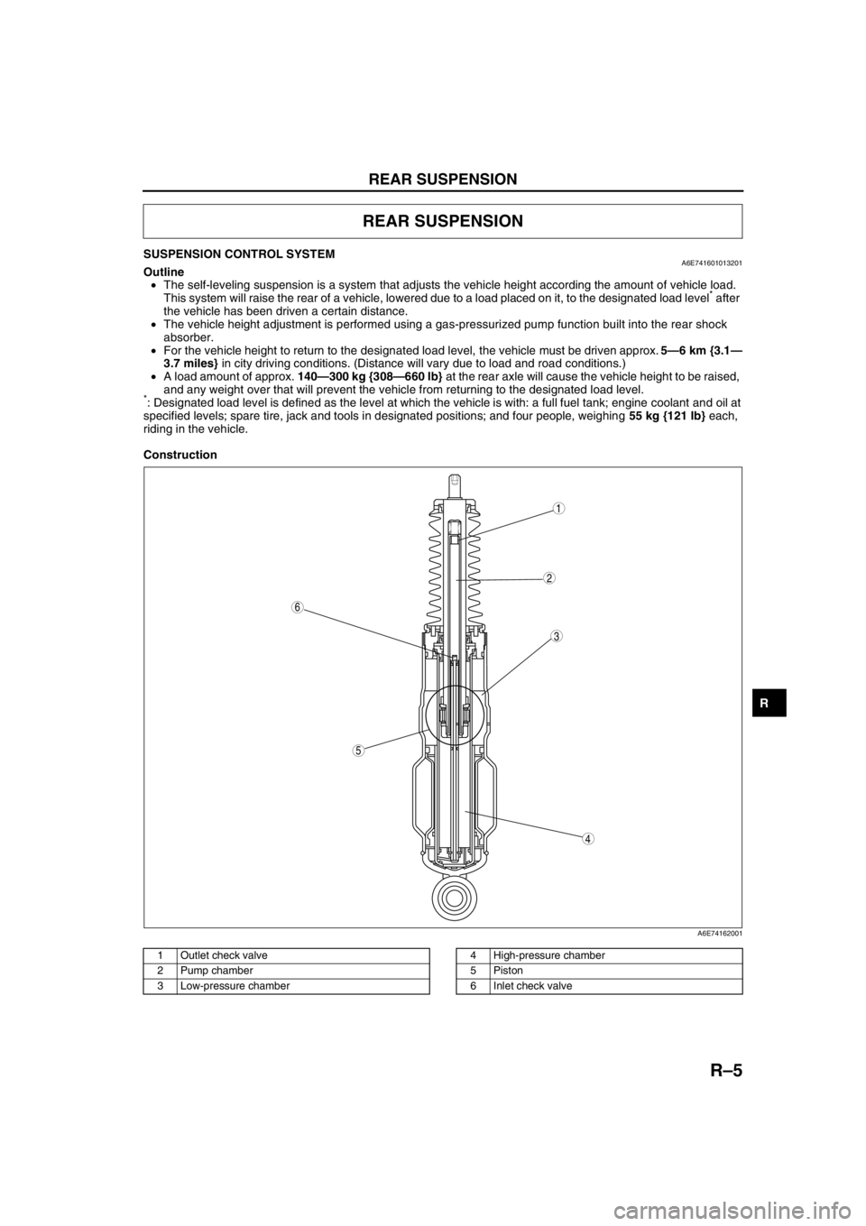
SUSPENSION CONTROL SYSTEMA6E741601013201Outline
•The self-leveling suspension is a system that adjusts the vehicle height according the amount of vehicle load.
This system will raise the rear of a vehicle, lowered due to a load placed on it, to the designated load level
* after
the vehicle has been driven a certain distance.
•The vehicle height adjustment is performed using a gas-pressurized pump function built into the rear shock
absorber.
•For the vehicle height to return to the designated load level, the vehicle must be driven approx. 5—6 km {3.1—
3.7 miles} in city driving conditions. (Distance will vary due to load and road conditions.)
•A load amount of approx. 140—300 kg {308—660 lb} at the rear axle will cause the vehicle height to be raised,
and any weight over that will prevent the vehicle from returning to the designated load level.
*: Designated load level is defined as the level at which the vehicle is with: a full fuel tank; engine coolant and oil at
specified levels; spare tire, jack and tools in designated positions; and four people, weighing 55 kg {121 lb} each,
riding in the vehicle.
Construction
.
REAR SUSPENSION
5
4
3
6
1
2
A6E74162001
1 Outlet check valve
2 Pump chamber
3 Low-pressure chamber4 High-pressure chamber
5Piston
6 Inlet check valve
Page 900 of 909

TD–8
TECHNICAL DATA
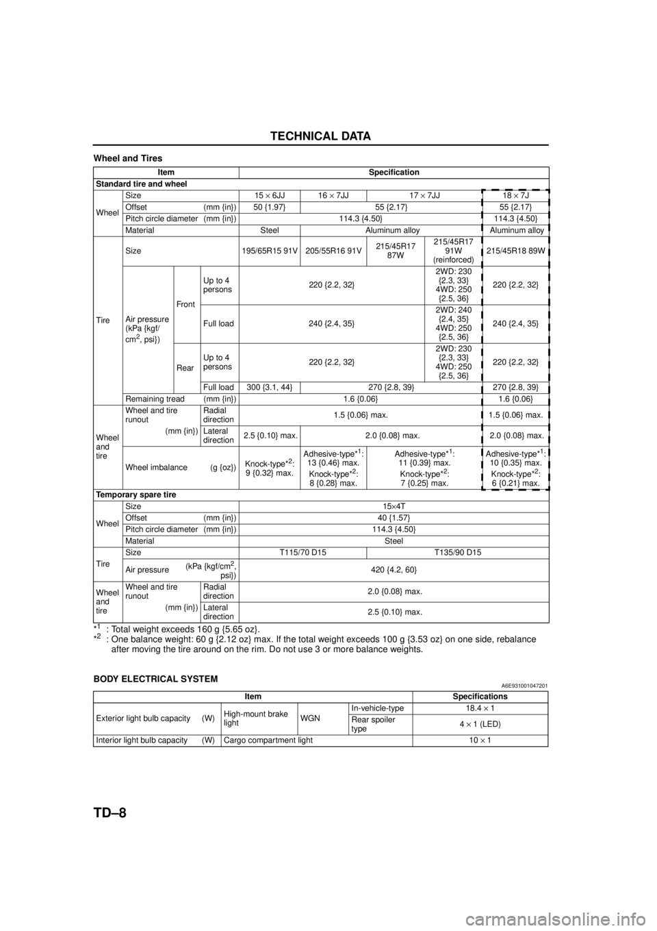
Wheel and Tires
*
1: Total weight exceeds 160 g {5.65 oz}.
*2: One balance weight: 60 g {2.12 oz} max. If the total weight exceeds 100 g {3.53 oz} on one side, rebalance after moving the tire around on the rim. Do not use 3 or more balance weights.
End Of Sie
BODY ELECTRICAL SYSTEMA6E931001047201
End Of Sie
Item Specification
Standard tire and wheel
Wheel Size 15
× 6JJ 16 × 7JJ 17 × 7JJ 18 × 7J
Offset (mm {in}) 50 {1.97} 55 {2.17} 55 {2.17}
Pitch circle diameter (mm {in}) 114.3 {4.50} 114.3 {4.50}
Material Steel Aluminum alloy Aluminum alloy
Tire Size 195/65R15 91V 205/55R16 91V
215/45R17
87W 215/45R17
91W
(reinforced) 215/45R18 89W
Air pressure
(kPa {kgf/
cm
2, psi}) Front
Up to 4
persons
220 {2.2, 32} 2WD: 230
{2.3, 33}
4WD: 250 {2.5, 36} 220 {2.2, 32}
Full load 240 {2.4, 35} 2WD: 240
{2.4, 35}
4WD: 250 {2.5, 36} 240 {2.4, 35}
Rear Up to 4
persons
220 {2.2, 32} 2WD: 230
{2.3, 33}
4WD: 250 {2.5, 36} 220 {2.2, 32}
Full load 300 {3.1, 44} 270 {2.8, 39} 270 {2.8, 39}
Remaining tread (mm {in}) 1.6 {0.06} 1.6 {0.06}
Wheel
and
tire Wheel and tire
runout
Radial
direction
1.5 {0.06} max. 1.5 {0.06} max.
(mm {in}) Lateral direction 2.5 {0.10} max. 2.0 {0.08} max. 2.0 {0.08} max.
Wheel imbalance (g {oz}) Knock-type*
2:
9 {0.32} max. Adhesive-type*
1:
13 {0.46} max.
Knock-type*
2:
8 {0.28} max. Adhesive-type*
1:
11 {0.39} max.
Knock-type*
2:
7 {0.25} max. Adhesive-type*
1:
10 {0.35} max.
Knock-type*
2:
6 {0.21} max.
Temporary spare tire
Wheel Size 15
×4T
Offset (mm {in}) 40 {1.57}
Pitch circle diameter (mm {in}) 114.3 {4.50}
Material Steel
Tire Size T115/70 D15 T135/90 D15
Air pressure
(kPa {kgf/cm
2,
psi}) 420 {4.2, 60}
Wheel
and
tire Wheel and tire
runout
Radial
direction
2.0 {0.08} max.
(mm {in}) Lateral direction 2.5 {0.10} max.
Item Specifications
Exterior light bulb capacity (W) High-mount brake
lightWGNIn-vehicle-type 18.4
× 1
Rear spoiler
type 4
× 1 (LED)
Interior light bulb capacity (W) Cargo compartment light 10 × 1
Page 907 of 909

ST–6
SPECIAL TOOLS
End Of Sie
49 0107 680A
Engine stand49 T032 317
Weight49 T032 316
Shaft
49 L027 004
Gear case
remover49 L027 0A0
Locknut
replacer set49 L027 006
Serrate socket
(Part of 49 L027
0A0)
49 L027 007
Hex socket
(Part of 49 L027
0A0)49 F401 366A
Plate49 B027 003
Attachment M
49 F401 331
Body49 F401 337A
Attachment C49 M005 797
Handle
49 F027 007
Attachment
φ 7249 G027 004
Gauge block49 8531 565
Drive pinion
model
49 8531 567
Collar A
(Part of 49 8531
565)49 8531 568
Collar B
(Part of 49 8531
565)49 G032 347
Oil seal installer
49 0727 570
Pinion height
gauge body49 S033 108
Bearing installer49 W010 107A
Installer
49 S032 333
Bearing installer49 E027 002
AttachmentWDS