stop start MAZDA 626 1987 Workshop Manual
[x] Cancel search | Manufacturer: MAZDA, Model Year: 1987, Model line: 626, Model: MAZDA 626 1987Pages: 1865, PDF Size: 94.35 MB
Page 330 of 1865

2B
ENGINE OIL, OIL
FILTER
86U02X-006
76G02B-010
86U02X-008
ENGINE OIL
REPLACEMENT
1. Warm up the engine to the normal operating tem-
perature and stop it.
2. Remove the oil filler cap and the oil pan drain plug.
3. Drain the oil into a suitable container.
Warning
Be careful when draining, the oil is very hot.
4. Install the drain plug and a new gasket.
Tightening torque:
29—41 N-m (3.0—4.2 m-kg, 22—30 ft-lb)
5. Refill the engine with the specified type and amount
of oil.
6. Refit the oil filler cap.
Oil pan capacity:
5.0 liters (5.3 US qt, 4.4 Imp qt)
7. Recheck the oil level after the engine has been run.
OIL
FILTER
REPLACEMENT
1. Remove the oil filter with a suitable wrench.
2. Use a clean rag to wipe off the mounting surface
on the engine.
3. Apply a coat of engine oil to the filter rubber seal.
4. Install the oil filter until the rubber seal contacts the
oil cooler by hand. Then tighten it a 7/6 turn fur-
ther with a band type wrench.
5. Start the engine and inspect around the filter seal
for leaks.
6. Check the oil level and add oil if necessary.
Oil filter capacity:
0.50 liters (0.52 US qt, 0.44 Imp qt)
76G02B-011
2B—6
Page 380 of 1865

OUTLINE 4A
SPECIFICATIONS
F6 & F8 Engine
Engine F6 F8
Specification General Singapore General
ECE,
Hong Kong, &
Singapore
Idle speed
rpm
MTX 800
+58
Idle speed
rpm
ATX 950
t5§
(in N range)|
900 +5§ (in N
range)
CO concentration
%
2.0
± 0.5
(Without secondary
air
injection)
Carburetor
Type Down draft, two barrel
Throat diameter
mm (in)
Primary 30 (1.18) Throat diameter
mm (in)
Secondary 34 (1.34)
Venturi diameter
mm
(in) Primary 23.5 (0.93) Venturi diameter
mm
(in) Secondary 29.0 (1.14)
Main nozzle
mm (in)
Primary 2.6 (0.10) Main nozzle
mm (in)
Secondary 2.8 (0.11)
Main
jet mm (in)
Primary MTX 1.10 (0.0433) 1.09 (0.0429) 1.14 (0.045)
Main
jet mm (in)
Primary ATX 1.10 (0.0433) 1.08 (0.0425) 1.12 (0.044) Main
jet mm (in)
Secondary 1.50 (0.059)
Main
air
bleed mm (in)
Primary MTX 0.60 (0.024) 0.60 (0.024) 0.55 (0.022) Main
air
bleed mm (in)
Primary ATX 0.60 (0.024) 0.80 (0.031) 0.60 (0.024) Main
air
bleed mm (in) Secondary 0.50 (0.020)
Slow
jet mm (in)
Primary 0.48 (0.019) 0.46 (0.018) Slow
jet mm (in)
Secondary 1.00 (0.039) 1.10 (0.043)
Slow
air
bleed mm (in)
Primary No.1 0.80 (0.031)
Slow
air
bleed mm (in)
Primary No.2 1.90 (0.075) Slow
air
bleed mm (in) Secondary No.1 1.00 (0.039) 0.80 (0.031) Slow
air
bleed mm (in) Secondary No.2 0.50 (0.020)
Power
jet mm (in)
0.50 (0.0201
Fast idle adjustment
mm (in)
Clearance between
Drimarv
throttle valve and bore
1.40-1.76 (0.055—0.069) MTX: 0.48-0.64 (0.019-0.025) ATX: 0.56-0.72 (0.022-0.028)
Float level adjustment mm (in)
Max. fuel flow
"L"
Clearance between
flo
44 (17.3)
at and
air
horn without aasket Float level adjustment mm (in) Fuel stop
"H"
12.5(0.49)
Clearance between float and
air
horn without aasket; float lowered
by
own weight
Choke breaker diaphragm mmHg (inHg)
Start 180-240 (7.1—9.5) 100-160 (3.9—6.3) Choke breaker diaphragm mmHg (inHg) Stop 290-350 (11.4—13.8) 220—280 8.7—11.01
Choke opener mmHg (inHg) Start 35-65 (1.4-2.6)
...
35-65 (1.4-2.6) Choke opener mmHg (inHg) Stop
......
130-190 (5.1-7.5) 130-190 (5.1-7.5)
Fuel tank capacity
Liters (US gal, Imp gal) 60 (15.9, 13.2)
Fuel Dump
Delivery pressure kPa (kg/cm2,
psi)
20-26 (0.20-0.27, 2.8—3.8)
Feeding capacity cc/min (cu in/min) More than 860 (52.5)
at
idle
Fuel filter
Type Paper element with magnet
Air cleaner
Fresh-Hot switching Manual Diaphragm type
Element tvoe Oil permeated paper
Fuel specification Leaded regular
76G04A-513
4 A—15
Page 381 of 1865

4A OUTLINE
FE Engine
Engine FE 8Valve FE 12Valve FE 8Valve
Specification General Middle East
ECE, Hong Kong, & Singapore Unleaded fuel
Idle speed
rpm
MTX 800
+5§
850
+5§
Idle speed
rpm
ATX 900
+58 (in N
range)
CO concentration
%
2.0
± 0.5
(Without secondary
air
injection)
Carburetor
Type Down draft,
two
barrel
Throat diameter
mm (in)
Primary 30 (1.18) Throat diameter
mm (in)
Secondary 34 (1.34)
Venturi diameter
mm (in)
Primary 23.5 (0.93) Venturi diameter
mm (in)
Secondary 29.0 (1.14)
Main nozzle
mm (in)
Primary 2.6 (0.10) Main nozzle
mm (in)
Secondary 2.8 (0.11)
Main
jet mm (in)
Primary MTX 1.14 (0.045) 1.09 (0.0429) 1.14 (0.045) 1.09 (0.0429) Main
jet mm (in)
Primary ATX 1.12 (0.044) 1.08 (0.0425) 1.12 (0.044) 1.09 (0.0429) Main
jet mm (in)
Secondary 1.55 (0.061) 1.50 (0.059) 1.55 (0.061) 1.50 (0.059)
Main
air
bleed
mm (in)
Primary MTX 0.50 (0.020) 0.60(0.024) 0.50 (0.020) 0.50 (0.020) Main
air
bleed
mm (in)
Primary ATX 0.55 (0.022) 0.80 (0.031) 0.55 (0.022) 0.50 (0.020) Main
air
bleed
mm (in) Secondary 0.50 (0.020)
Slow
jet mm (in)
Primary 0.46 (0.018)
Slow
jet mm (in)
Secondary MTX 1.10 (0.043) 1.00 (0.039) 1.10 (0.043) 0.90 (0.035) Slow
jet mm (in)
Secondary ATX 1.10 (0.043) 1.00 (0.039) 1.10 (0.043) 1.00 (0.039)
Slow
air
bleed
mm (in)
Primary No.1 0.80 (0.031)
Slow
air
bleed
mm (in)
Primary No.2 1.90 (0.075) Slow
air
bleed
mm (in) Secondary No.1 0.80 (0.031) 1.00 (0.039) 0.80 (0.031) 1.00 (0.039)
Slow
air
bleed
mm (in) Secondary No.2 0.50 (0.020)
Power
jet mm (in)
MTX 0.50 (0.020) 0.50 (0.020) Power
jet mm (in)
ATX 0.50 (0.020) 0.40 (0.016)
Fast idle adjustment
mm (in)
Clearance between primary throttle valve and bore
MTX 0.48—0.64
(0.019-0.025) 1.40—1.76
(0.055-0.069)
0.48—0.64
(0.019-0.025) 1.40-1.76
(0.055-0.069)
Fast idle adjustment
mm (in)
Clearance between primary throttle valve and bore ATX 0.56-0.72 (0.022—0.028)
1.40—1.76
(0.055-0.069) 0.56-0.72 (0.022—0.028)
1.40-1.76
(0.055-0.069)
Float level adjust-
ment
mm (in)
Max. fuel flow
"L"
Clearance between
flo
44 (17.3)
at and
air
horn without aasket Float level adjust-
ment
mm (in)
Fuel stop
"H" |
12.5(0.49)
Clearance between float and
air
horn without aasket: float lowered
bv
own weiaht
Choke breaker diaphragm mm-Hg (in-Hg)
Start 100-160 (3.9—6.3) 180—240 (7.1-9.4) 100-160
(3.9-6.3)
180-240
(7.1-9.4) Choke breaker diaphragm mm-Hg (in-Hg) Stop 220—280
(8.7-11.0)
290-350
(11.4-13.8)
220—280
(8.7-11.0)
290-350
(11.4-13.8)
Choke opener mmHg (inHg)
Start 80—120
(3.1-8.7)
30-70 (1.2-2.8) Choke opener mmHg (inHg)
Stop 220-280 (8.7—11.0) 130-190
(5.1-7.5)
Fuel tank capacity
Liters (US aal, Imp aal) 60 (15.9, 13.2)
Fuel DumD
Delivery pressure kPa (kg/cm2,
psi)
20-26 (0.20—0.27, 2.8-3.8) 20-29 (0.20-0.30, 2.8-4.3)
20-26 (0.20-0.27, 2.8-3.8)
Feedina caDacitv cc/min
feu
in/mini More than 860 (52.5)
at
idle
Fuel filter
Type Paper element with magnet
Air cleaner
Fresh-Hot switchina Diaphragm Manual Diaphragm Bimetal
Element
tvDe
Oil permeated paper
Fuel specification Leaded super
Unleaded super Leaded regular Leaded super Unleaded super Unleaded regular
76G04G-514
4A—16
Page 398 of 1865

FUEL SYSTEM 4A
76G04A-040
76G04A-041
Clearance
® J t'YCL ® J
V hi /®
'-v
76G04A-042
Fast Idle Opening
FE and F8 (General, ECE, Hong Kong, and Sin-
gapore)
Adjustment of fast idle opening is normally un-
necessary.
But if it is necessary, adjust it as shown.
1. Before adjustment, let the carburetor set at 25WC
(77°F) for at least 1 hour.
2. Check that the center of the cam lever aligns with
the mark (25°) on the fast idle cam.
3. If not as specified, adjust it by turning the adjust
screw.
4. Measure the throttle valve clearance between the
throttle valve and wall with a wire gage.
Specification
Spec. General, ECE, Hong Kong,
and Singapore
Transmission MTX ATX
Clearance mm (in) 0.48—0.64
(0.019-0.025)
0.56—0.72 (0.022-0.028)
5. If not as specified, adjust it by turning the fast idle
adjust screw.
Unloader System
Only FE and F8 (General, ECE, Hong Kong, and
Singapore)
1. Open the primary throttle valve fully.
2. Measure the choke valve clearance.
Clearance-
1.68—2.14 mm (0.066—0.084 in)
3. If not as specified, adjust it by bending tab A.
Slow Fuel Cut Solenoid Valve
1. Start the engine, and run it at idle.
2. Disconnect the connector of the carburetor.
3. Check that the engine stops.
4. If the engine does not stop, replace the slow fuel
cut solenoid valve.
76G04A-043
4A-33
Page 424 of 1865

AIR
INJECTION SYSTEM 4A
76G04A-109
Reed Valve
1. Warm up the engine to the normal operating tem-
perature, and then stop the engine.
2. Remove the air cleaner cover and element.
3. Start the engine and run it at idle.
4. Place a thin paper over the reed valve inlet port
and check that air is pulled in.
5. Increase the engine speed to 1,500 rpm and
check that there is no exhaust gas leakage at the
inlet by placing a thin paper over the port.
6. Replace the reed valve, if necessary.
76G04A-110
Air Injection Nozzle and Pipe
1. Disconnect the hoses from the air cleaner.
2. Loosen the nuts and remove the air injection noz-
zle and air pipe.
3. Visually check the air injection nozzle and pipe.
4. Replace if necessary.
76G04A-111
4A-59
Page 488 of 1865

4B SWITCH MONITOR FUNCTION
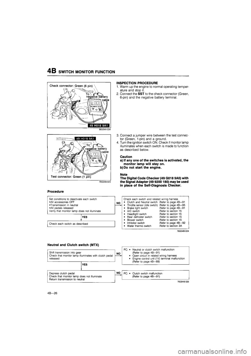
49 H018 9A1
INSPECTION PROCEDURE
1. Warm up the engine to normal operating temper-
ature and stop it.
2. Connect the SST to the check connector (Green,
6-pin) and the negative battery terminal.
86U04A-034
76G04B-023
3. Connect a jumper wire between the test connec-
tor (Green, 1-pin) and a ground.
4. Turn the ignition switch ON. Check if monitor lamp
illuminates when each switch is made to function
as described below.
Caution
a) If any one of the switches is activated, the
monitor lamp will stay on.
b) Do not start the engine.
Note
The Digital Code Checker (49 G018 9A0) with
the Signal Adapter (49 9200180) may be used
in place of the Self-Diagnosis Checker.
Procedure
76G04B-024
4B—26
Page 517 of 1865

FUEL SYSTEM 4B
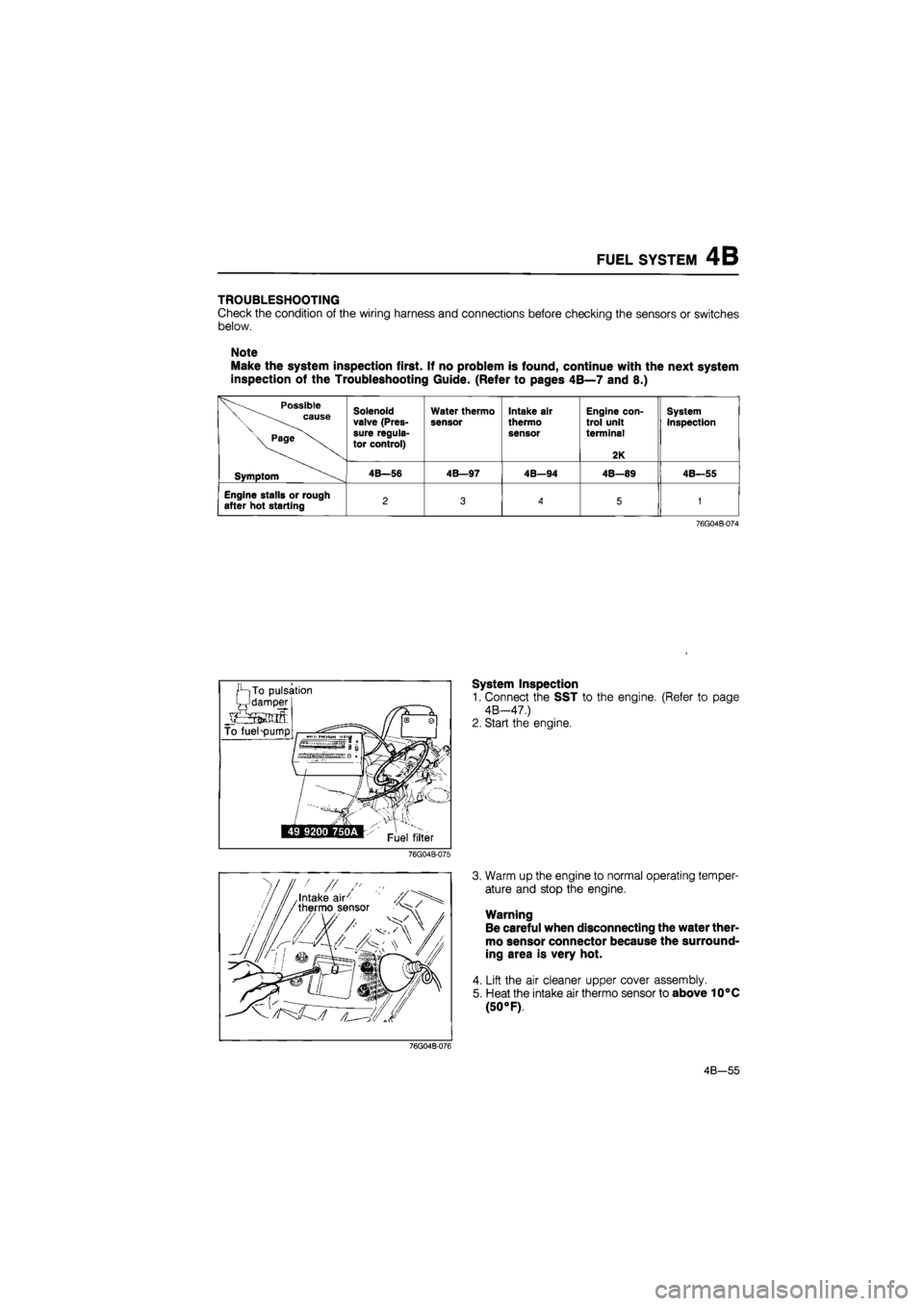
TROUBLESHOOTING
Check the condition of the wiring harness and connections before checking the sensors or switches
below.
Note
Make the system inspection first. If no problem is found, continue with the next system
inspection of the Troubleshooting Guide. (Refer to pages 4B—7 and 8.)
Possible \ cause
\ Page
Solenoid valve (Pres-sure regula-tor control)
Water thermo
sensor Intake air
thermo sensor
Engine con-trol unit terminal
2K
System inspection
Symptom 4B—56 4B—97 4B—94 4B—89 4B—55
Engine stalls or rough after hot starting 2 3
A
5 1
76G04B-074
System Inspection
1. Connect the SST to the engine. (Refer to page
4B—47.)
2. Start the engine.
76G04B-075
3. Warm up the engine to normal operating temper-
ature and stop the engine.
Warning
Be careful when disconnecting the water ther-
mo sensor connector because the surround-
ing area is very hot.
4. Lift the air cleaner upper cover assembly.
5. Heat the intake air thermo sensor to above 10°C
(50 °F).
76G04B-076
4B—55
Page 536 of 1865

4B EEC SYSTEM
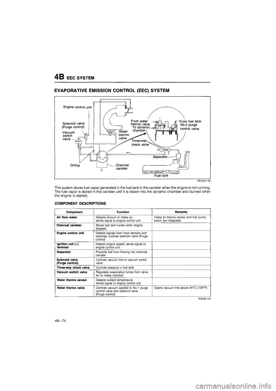
EVAPORATIVE EMISSION CONTROL
(EEC)
SYSTEM
Engine control unit
Solenoid valve
(Purge control)
Vacuum
switch
valve x
From water thermo valve To dynamic -chamber
Three-way
check valve
Orifice Charcoal
canister
From fuel tank
No.2 purge
control valve
Fuel tank
86U04A-136
This system stores fuel vapor generated in the fuel tank in the canister when the engine is not running.
The fuel vapor is stored in the canister until it is drawn into the dynamic chamber and burned when
the engine is started.
COMPONENT DESCRIPTIONS
Component Function Remarks
Air flow meter Detects amount of intake air; sends signal to engine control unit
Intake air thermo sensor and fuel pump
switch are integrated
Charcoal canister Stores fuel tank fumes when engine
stopped
Engine control unit Detects signals from input sensors and switches; controls solenoid valve (Purge control)
Ignition coil (-)
terminal Detects engine speed; sends signal to
engine control unit
Separator Prevents fuel from flowing into charcoal canister
Solenoid valve (Purge control) Controls vacuum line to vacuum switch valve
Three-way check valve Controls pressure in fuel tank
Vacuum switch valve Regulates evaporative fumes from canis-
ter to intake manifold
Water thermo sensor Detects coolant temperature; sends signal to engine control unit
Water thermo valve Controls vacuum applied to No.1 purge control valve and solenoid valve (Purge control)
Opens vacuum line above 54°C (129°F)
76G04B-104
4B—74
Page 587 of 1865

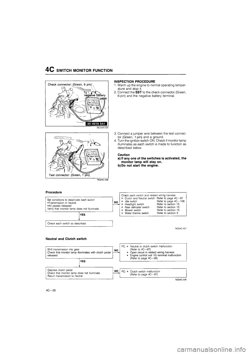
4C SWITCH MONITOR FUNCTION
Check connector: (Green, 6 pin)'
N negative battery
ii cable
49 H018 9A1
INSPECTION PROCEDURE
1. Warm up the engine to normal operating temper-
ature and stop it.
2. Connect the SST to the check connector (Green,
6-pin) and the negative battery terminal.
86U04A-034
Test connector: (Green, 1 pin)
3. Connect a jumper wire between the test connec-
tor (Green, 1-pin) and a ground.
4. Turn the ignition switch ON. Check if monitor lamp
illuminates as each switch is made to function as
described below.
Caution
a) If any one of the switches is activated, the
monitor lamp will stay on.
b)Do not start the engine.
76G04C-036
76G04C-037
Neutral and Clutch switch
4C—26
Page 631 of 1865

4C PRC SYSTEM
System Inspection
1. Connect the SST to the engine. (Refer to page
4C-53.)
2. Start the engine.
76G04C-131
Hi?
Jpll ssil
Water thermo sensor ^^^Tta^e air thermo sensor
76G04C-132
Operating time Fuel line pressure kPa (kg/cm2, psi)
After starting: for 120 sec. 235-275 (2.4-2.8, 34-40)
After 120 sec. 186-226 (1.9-2.3, 27-33)
3. Warm up the engine to normal operating temper-
ature and stop the engine.
Warning
Be careful when disconnecting the water ther-
mo sensor connector because the surround-
ing area is very hot.
4. Disconnect the water thermo sensor connector.
Connect a resistor (200 fl) to the sensor connector.
5. Heat the intake air thermo sensor to above specifi-
cation.
Specification: 30°C (86°F)....unleaded fuel
50°C (122°F)....leaded fuel
6. Restart the engine.
7. Check the fuel line pressure and operating times
as shown in the chart.
76G04C-133
Solenoid Valve (Pressure Regulator Control)
Inspection
1. Disconnect the vacuum hose from the vacuum
pipe.
2. Blow through the solenoid valve from vacuum hose
A.
3. Check that air flows from port B.
76G04C-134
4C—70