tow MAZDA 626 1987 Workshop Manual
[x] Cancel search | Manufacturer: MAZDA, Model Year: 1987, Model line: 626, Model: MAZDA 626 1987Pages: 1865, PDF Size: 94.35 MB
Page 3 of 1865

GENERAL INFORMATION
IMPORTANT INFORMATION G— 2
FUNDAMENTAL PROCEDURES G— 2
JACK AND SAFETY STAND (RIGID RACK)
POSITIONS G— 6
VEHICLE LIFT (2-SUPPORT TYPE)
POSITIONS G- 7
TOWING G— 8
CHASSIS NUMBER LOCATION G— 9
ENGINE MODEL AND NUMBER
LOCATION G— 9
UNITS G— 9
ABBREVIATIONS G— 9
CAUTION G—10 76G0GX-001
Page 10 of 1865

G TOWING
76GOGX-OQ2
i-^C.
y -
- r^jfftj&H
r —I
76UQGX-003
86U0GX-004
G—8
TOWING
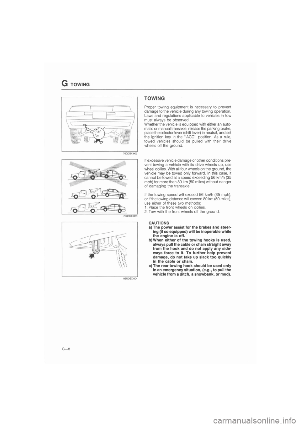
Proper towing equipment is necessary to prevent
damage to the vehicle during any towing operation.
Laws and regulations applicable to vehicles in tow
must always be observed.
Whether the vehicle is equipped with either an auto-
matic or manual transaxle, release the parking brake,
place the selector lever (shift lever) in neutral, and set
the ignition key in the "ACC" position. As a rule,
towed vehicles should be pulled with their drive
wheels off the ground.
If excessive vehicle damage or other conditions pre-
vent towing a vehicle with its drive wheels up, use
wheel dollies. With all four wheels on the ground, the
vehicle may be towed only forward. In this case, it
cannot be towed at a speed exceeding 56 km/h (35
mph) for more than 80 km (50 miles) without danger
of damaging the transaxle.
If the towing speed will exceed 56 km/h (35 mph),
or if the towing distance will exceed 80 km (50 miles),
use either of these two methods:
1. Place the front wheels on dollies.
2. Tow with the front wheels off the ground.
CAUTIONS
a) The power assist for the brakes and steer-
ing (if so equipped) will be inoperable while
the engine is off.
b)When either of the towing hooks is used,
always pull the cable or chain straight away
from the hook and do not apply any side-
ways force to it. To further help prevent
damage, do not take up slack too quickly
in the cable or chain.
c) The rear towing hook should be used only
in an emergency situation, (e.g., to pull the
vehicle from a ditch, a snowbank, or mud).
Page 62 of 1865

1 A ON-VEHICLE MAINTENANCE (VALVE SEAL)
Installation note
Valve seal
1. Apply engine oil to the inside of the new valve seal.
2. Push it on gently with the SST.
86U01X-049
Valve spring
Cylinder head side
Valve spring
1. (12-valve)
Install the valve spring with the narrower pitch to-
ward the cylinder head side.
(8-valve)
Install the outer valve spring with the narrower pitch
toward the cylinder head side.
2. Install the valve keepers, and tap the end of the
valve stem lightly two or three times with a plastic
hammer to confirm that the keepers are all fully
seated.
76G01A-038
12-valve Rocker arm, rocker arm shaft
1. Remove the rocker arm shafts and camshaft caps.
2. (12-valve)
Assemble the rocker arms and springs to the shaft.
Note
a) The intake side shaft has twice as many oil
holes as the exhaust side shaft.
b) The stepped ends are the rear sides of both
intake and exhaust shafts.
76G01A-039
(8-valve)
Assemble the camshaft caps, rocker arms, and
springs, to the shafts.
Caution
Be sure both rocker arm shaft oil holes (in the
center camshaft cap) face each other.
76G01A-040
1A—30
Page 101 of 1865

ASSEMBLY (CYLINDER BLOCK) 1 A
3. Install the rear cover and a new gasket.
Tightening torque:
8—12 N-m (80—120 cm-kg, 69—104 in-lb)
86U01X-131
4. Cut away the portion of the gasket that projects out
from the rear cover assembly toward the oil pan
side.
Caution
Do not scratch the rear cover assembly.
86U01X-132
End Plate
Install the end plate.
Tightening torque:
19—30 N-m (1.9—3.1 m-kg, 14—22 ft-lb)
4BG01A-160
Oil Pump
1. Apply engine oil to a new oil pump oil seal and the
oil pump body.
2. Press the oil seal into the oil pump body.
79G01C-085
1
A—69
Page 106 of 1865

ASSEMBLY (CYLINDER HEAD) 1 A
86U01X-144
Valve and Valve Spring
1. Install the lower spring seat.
2. Install the valve.
3. Install the valve springs and the upper spring seat.
Note
Install the valve spring with the closer pitch
toward the cylinder head.
4. Compress the valve spring with the SST; then in-
stall the valve keepers.
5. Tap the end of the valve stem lightly two or three
times with a plastic hammer to confirm that the
keepers are all fully seated.
Cylinder Head
1. Thoroughly remove all dirt, oil, or other material
from the top of the cylinder block.
2. Place the new cylinder head gasket in position.
3. Install the cylinder head.
4. Apply engine oil to the bolt threads and seat faces.
5. Tighten the cylinder head bolts in two or three steps
in the order shown in the figure.
Tightening torque:
80—86 Nm (8.2—8.8 m-kg, 59—64 ft-lb)
1A—74
Page 111 of 1865

ASSEMBLY (CYLINDER HEAD) 1 A
Outer valve spring
®
®
Cylinder head r
Side ®>d)
76G01A-079
86U01X-145
86U01X-146
© @ ® ©
© ® © ®
Valve and Valve Spring
1. Install the lower spring seat.
2. Install the valve.
3. Install the valve springs and the upper spring seat.
Note
Install the outer valve spring with the closer
pitch toward the cylinder head.
4. Compress the valve spring with the SST; then in-
stall the valve keepers.
5. Tap the end of the valve stem lightly two or three
times with a plastic hammer to confirm that the
keepers are all fully seated.
Cylinder Head
1. Thoroughly remove all dirt, oil, or other material
from the top of the cylinder block.
2. Place the new cylinder head gasket in position.
3. Install the cylinder head.
4. Apply engine oil to the bolt threads and seat faces.
5. Tighten the cylinder head bolts in two or three steps
in the order shown in the figure.
Tightening torque:
80—86
N
m (8.2—8.8 m-kg, 59—64 ft-lb)
86U01X-147
1A—79
Page 186 of 1865

ASSEMBLY (CYLINDER BLOCK) 1 B
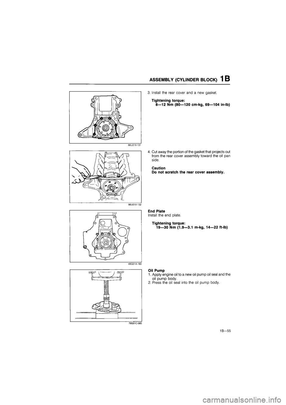
3. Install the rear cover and a new gasket.
Tightening torque:
8—12 N-m (80—120 cm-kg, 69—104 in-lb)
86U01X-131
4. Cut away the portion of the gasket that projects out
from the rear cover assembly toward the oil pan
side.
Caution
Do not scratch the rear cover assembly.
86U01X-132
End Plate
Install the end plate.
Tightening torque:
19—30 Nm (1.9—3.1 m-kg, 14—22 ft-lb)
4BG01A-160
Oil Pump
1. Apply engine oil to a new oil pump oil seal and the
oil pump body.
2. Press the oil seal into the oil pump body.
79G01C-085
1B—55
Page 191 of 1865

1 B ASSEMBLY (CYLINDER HEAD)
Valve spring
®>®
Cylinder head side
76G01B-084
86U01X-145
76G01B-085
Valve and Valve Spring
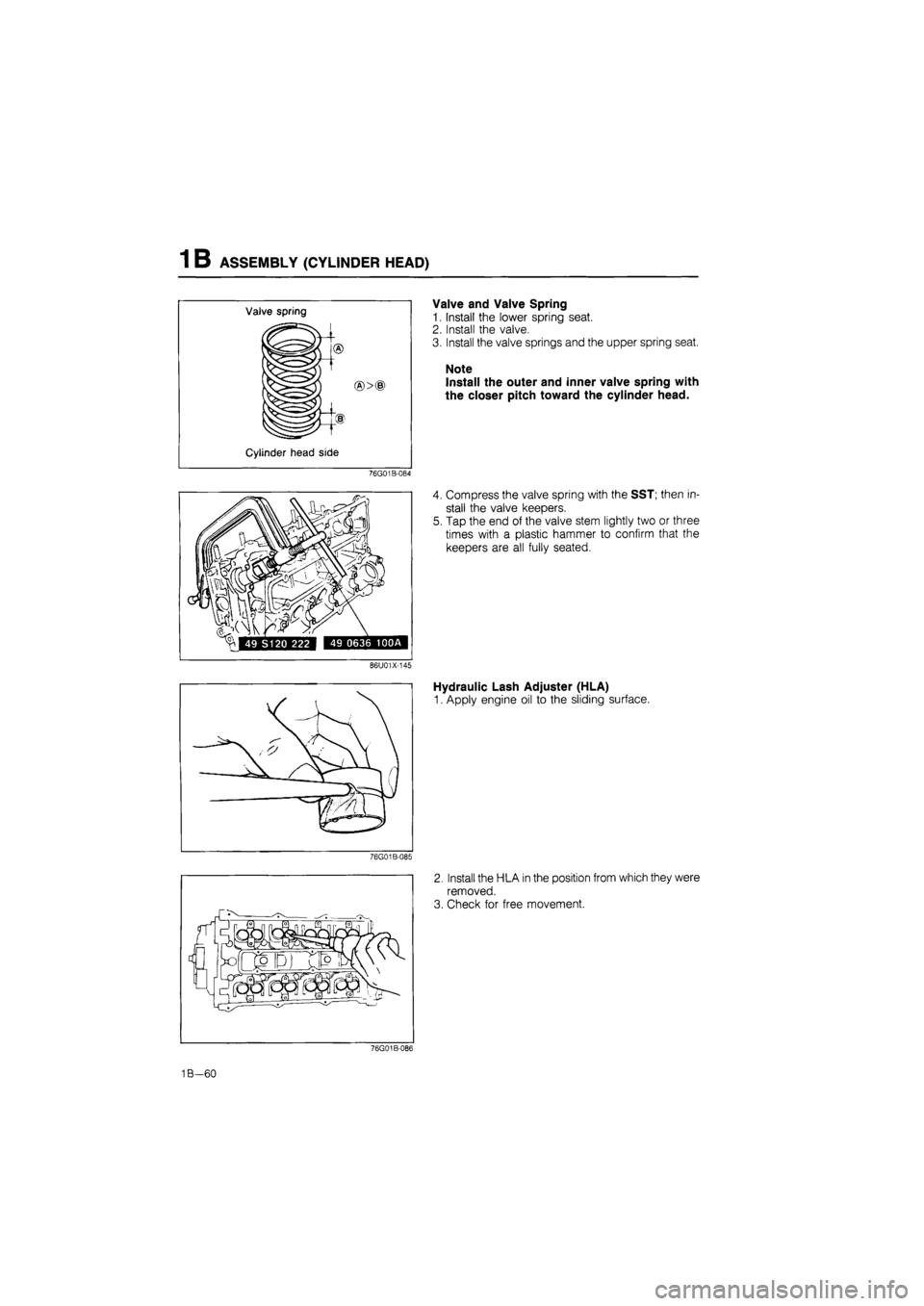
1. Install the lower spring seat.
2. Install the valve.
3. Install the valve springs and the upper spring seat.
Note
Install the outer and inner valve spring with
the closer pitch toward the cylinder head.
4. Compress the valve spring with the SST; then in-
stall the valve keepers.
5. Tap the end of the valve stem lightly two or three
times with a plastic hammer to confirm that the
keepers are all fully seated.
Hydraulic Lash Adjuster (HLA)
1. Apply engine oil to the sliding surface.
2. Install the HLA in the position from which they were
removed.
3. Check for free movement.
76G01B-086
1B—60
Page 281 of 1865

ASSEMBLY (CYLINDER BLOCK) 1 C
86U01X-131
86U01X-132
76G01C-161
3. Install the rear cover and a new gasket.
Tightening torque:
8—12 Nm (80—120 cm-kg, 69—104 in-lb)
4. Cut away the portion of the gasket that projects out
from the rear cover assembly toward the oil pan
side.
Caution
Do not scratch the rear cover assembly.
End Plate
Install the end plate.
Tightening torque:
19—26
N
m (1.9—2.6 m-kg, 14—19 ft-lb)
Oil Pump
1. Apply engine oil to a new oil pump oil seal and the
oil pump body.
2. Press the oil seal into the oil pump body.
79G01C-085
1C-69
Page 704 of 1865

FUEL SYSTEM 4D
76G04D-077
76G04D-078
^^^
76G04D-079
Red paint
Injection Nozzle Disassembly
Disassemble the injection nozzle.
1. Nozzle holder
2. Adjusting shim
3. Pressure spring
4. Pressure pin
5. Distance piece
6. Nozzle
7. Retaining ring
Cleaning
Clean the parts in clean test oil.
Injection Nozzle Inspection
1. Check the needle valve, nozzle body, and other
parts for damage.
2. Hold the nozzle body upright and insert approxi-
mately two thirds of the needle valve, and check
that the needle valve drops to the valve seat by
its own weight.
Injection Nozzle Assembly
1. Assemble the injection nozzle.
Tightening torque of nozzle body:
29—49 N-m (3.0—5.0 m-kg, 22—36 ft-lb)
2. Check the injection starting pressure, and atomi-
zation. (Refer to page 4D—32.)
Injection Nozzle Installation
1. Install in the reverse order of removal, referring to
the installation note.
2. Check for fuel leakage.
Installation note
Nozzle gasket
Install a new gasket with the red face toward the
nozzle.
76G04D-080
4D-33