Brake MAZDA 626 1987 Workshop Manual
[x] Cancel search | Manufacturer: MAZDA, Model Year: 1987, Model line: 626, Model: MAZDA 626 1987Pages: 1865, PDF Size: 94.35 MB
Page 1103 of 1865

CD
rv) GO -vi
2-4 brake band
toasting clutch pressure Low and reverse ' brake pressure
3-4 clutch pressure; •To oil cooler
N-R accumulator '2-3 accumulator
2-3 Timing valve 18 Coasting
Bypass valve Servo control v valve (Blocked)
Pressure modifier valve (Blocked)
Throttle modulator valve
3-4 shift valve
1-2 shift valve
Low reducing valve
19 Pressure regulator valve 20 3-2 timing valve 3-2 capacity valve Manual valve
••• Throttle pressure
Throttle modulated pressure
•• Line pressure
HH Operating line pressure
r I Low reducing pressure
I i Torque converter pressure
back-up valve (Blocked)
| Oil pump
1-2 accumulator ,
Forward clutch pressure^
Reverse clutch^ pressure-—__^
Lock-up control valve
Apply side
-< a
J3 >
o
o
30 o c
o >
• m
CD
Page 1108 of 1865

-vj CD
IV)
ro
o
2-4 brake
To forward clutch Throttle valve N-R accumulator 2-3 accumulator 1-2 accumu lator i N-D [accumulator
Coasting | bypass i n valve 2-3 timing valve Servo control valve
1-2 shift valve OD Lock-up valve
3-4 shift valve
Throttle backup valve 7=n 1 range r | control
•fl- Unn,Y?'ve.„;
Low reducing valve
2 range control valve •Pressure check port OD re-lease valve
Pressure regulator valve Lock-up support valve
Manual valve Kick-down valve 3-2 capacity valve
OD release solenoid valve Oil pump Pressure check port Pressure check port Governor valve 1-2 shift control valve
Line pressure
Operating line pressure
Throttle pressure
Throttle modulated pressure
i Governor pressure
Torque converter pressure
« Fx
Lock-up control valve
Throttle modulator valve
Apply side
Page 1111 of 1865
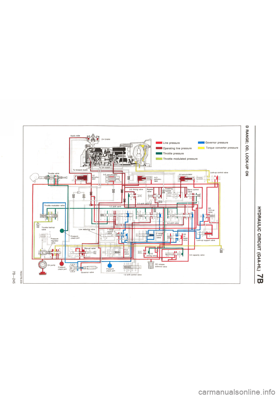
CD
cn
2-4 brake
To 3-4 clutch To forward clutch
Throttle valve 2-3 accumulator N-R accumulator 1-2 accumu' lator N-D accumu lator
Coasting bypass 1 n valve Servo control valve
1-2 shift valve
3-4 shift valve
Low reducing valve ri 1 range control -n n valve . ••MJ 2 range control | valve Pressure check port Pressure regulator valve
Manual valve Kick-down valve -13-2 timing valve.
Oil pump Pressure check port Pressure check port Governor valve
Throttle modulator valve
3-2 capacity valve
OD release solenoid valve
1-2 shift control valve
Throttle backup valve
Line pressure
Operating line pressure
Throttle pressure
Throttle modulated pressure
P
Governor pressure
Torque converter pressure
Apply side
2-3 timing valve
OD re-lease valve
Lock-up control valve
Lock-up support valve
OD lock-up valve
o
jj >
z a m
O o
o o *
c TJ
o
< a jj >
c •
o
o
J3 O
O 45b >
m
Page 1115 of 1865
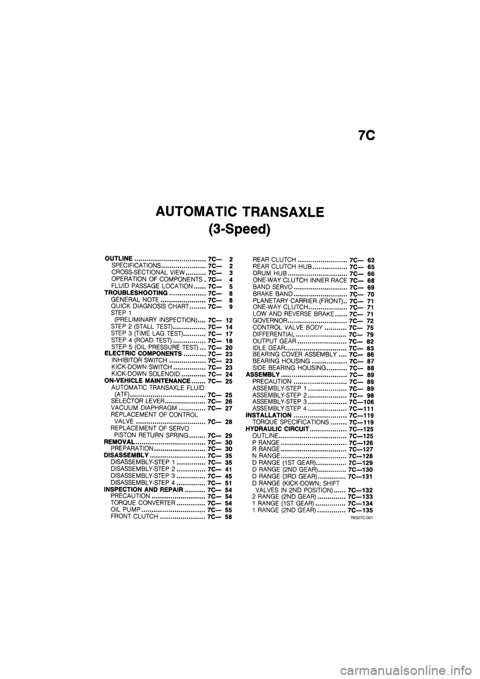
7C
AUTOMATIC TRANSAXLE
(3-Speed)
OUTLINE 7C— 2
SPECIFICATIONS 7C— 2
CROSS-SECTIONAL VIEW 7C— 3
OPERATION OF COMPONENTS . 7C— 4
FLUID PASSAGE LOCATION 7C— 5
TROUBLESHOOTING 7C— 8
GENERAL NOTE 7C— 8
QUICK DIAGNOSIS CHART 7C— 9
STEP 1
(PRELIMINARY INSPECTION).... 7C— 12
STEP 2 (STALL TEST) 7C— 14
STEP 3 (TIME LAG TEST) 7C— 17
STEP 4 (ROAD TEST) 7C— 18
STEP 5 (OIL PRESSURE TEST)... 7C— 20
ELECTRIC COMPONENTS 7C— 23
INHIBITOR SWITCH 7C— 23
KICK-DOWN SWITCH 7C— 23
KICK-DOWN SOLENOID 7C— 24
ON-VEHICLE MAINTENANCE 7C- 25
AUTOMATIC TRANSAXLE FLUID
(ATF) 7C— 25
SELECTOR LEVER 7C— 26
VACUUM DIAPHRAGM 7C— 27
REPLACEMENT OF CONTROL
VALVE 7C— 28
REPLACEMENT OF SERVO
PISTON RETURN SPRING 7C— 29
REMOVAL 7C— 30
PREPARATION 7C— 30
DISASSEMBLY 7C— 35
DISASSEMBLY-STEP 1 7C— 35
DISASSEMBLY-STEP 2 7C— 41
DISASSEMBLY-STEP 3 7C— 45
DISASSEMBLY-STEP 4 7C— 51
INSPECTION AND REPAIR 7C- 54
PRECAUTION 7C— 54
TORQUE CONVERTER 7C— 54
OIL PUMP 7C— 55
FRONT CLUTCH 7C— 58
REAR CLUTCH 7C— 62
REAR CLUTCH HUB 7C— 65
DRUM HUB 7C— 66
ONE-WAY CLUTCH INNER RACE 7C— 68
BAND SERVO 7C— 69
BRAKE BAND 7C— 70
PLANETARY CARRIER (FRONT).. 7C— 71
ONE-WAY CLUTCH 7C— 71
LOW AND REVERSE BRAKE 7C— 71
GOVERNOR 7C— 72
CONTROL VALVE BODY 7C— 75
DIFFERENTIAL 7C— 79
OUTPUT GEAR 7C— 82
IDLE GEAR 7C— 83
BEARING COVER ASSEMBLY .... 7C— 86
BEARING HOUSING 7C— 87
SIDE BEARING HOUSING 7C— 88
ASSEMBLY 7C— 89
PRECAUTION 7C— 89
ASSEMBLY-STEP 1 7C— 89
ASSEMBLY-STEP 2 7C— 98
ASSEMBLY-STEP 3 7C—106
ASSEMBLY-STEP 4 7C—111
INSTALLATION 7C—119
TORQUE SPECIFICATIONS 7C—119
HYDRAULIC CIRCUIT 7C—125
OUTLINE 7C—125
P RANGE 7C—126
R RANGE 7C—127
N RANGE 7C—128
D RANGE (1ST GEAR) 7C—129
D RANGE (2ND GEAR) 7C—130
D RANGE (3RD GEAR) 7C—131
D RANGE (KICK-DOWN; SHIFT
VALVES IN 2ND POSITION) 7C—132
2 RANGE (2ND GEAR) 7C—133
1 RANGE (1ST GEAR) 7C—134
1 RANGE (2ND GEAR) 7C—135
76G07C-001
Page 1116 of 1865
7C OUTLINE
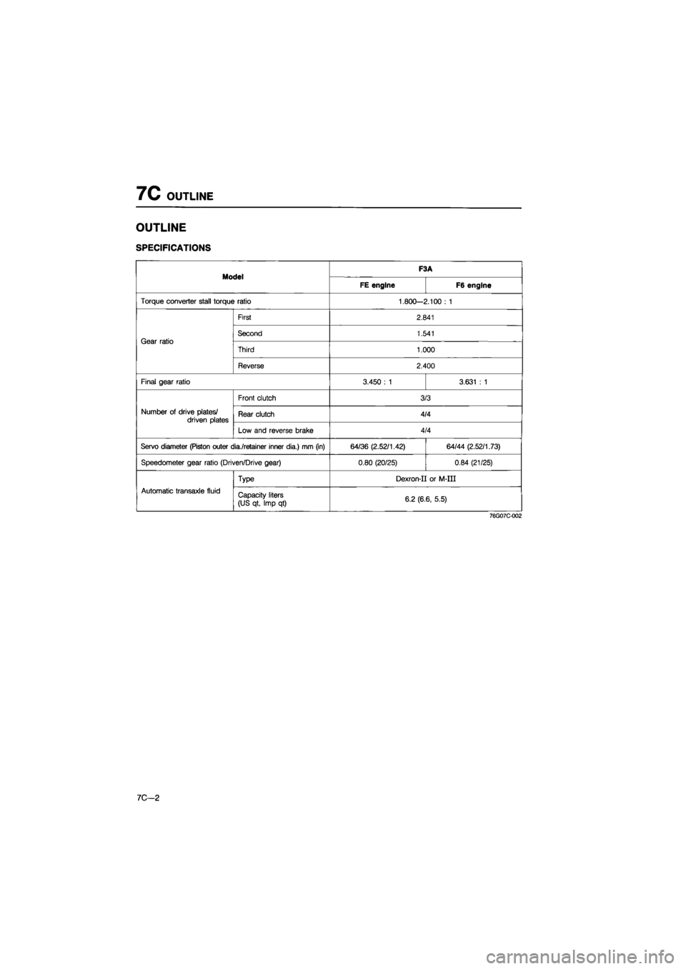
OUTLINE
SPECIFICATIONS
Model F3A Model FE engine F6 engine
Torque converter stall torque ratio 1.800-2.100 : 1
Gear ratio
First 2.841
Gear ratio Second 1.541 Gear ratio
Third 1.000
Gear ratio
Reverse 2.400
Final gear ratio 3.450 : 1 3.631 : 1
Number of drive plates/ driven plates
Front clutch 3/3
Number of drive plates/ driven plates Rear clutch 4/4 Number of drive plates/ driven plates
Low and reverse brake 4/4
Servo diameter (Piston outer dia./retainer inner dia.) mm (in) 64/36 (2.52/1.42) 64/44 (2.52/1.73)
Speedometer gear ratio (Driven/Drive gear) 0.80 (20/25) 0.84 (21/25)
Automatic transaxle fluid
Type Dexron-II or M-III
Automatic transaxle fluid Capacity liters
(US qt, Imp qt) 6.2 (6.6, 5.5)
76G07C-002
7C—2
Page 1117 of 1865
OUTLINE 7C
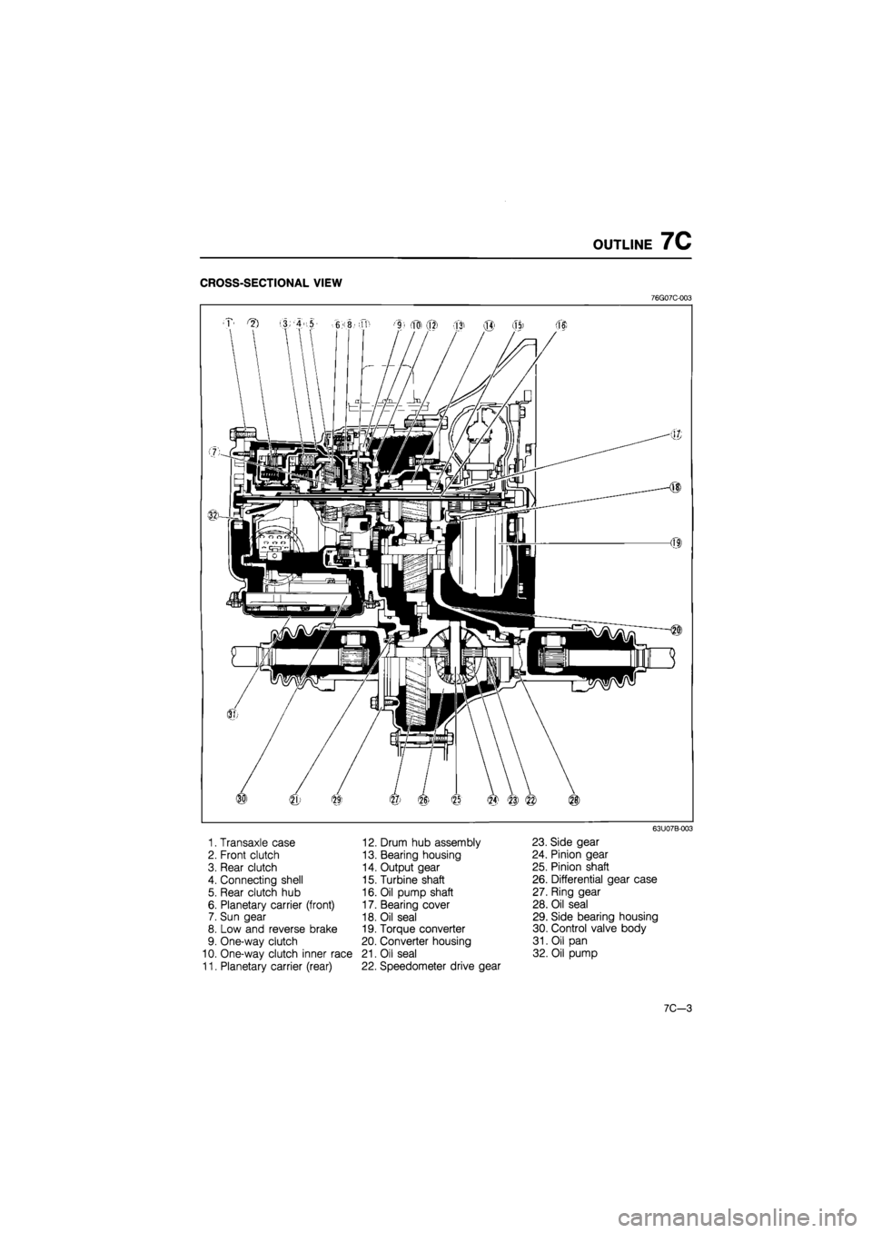
CROSS-SECTIONAL VIEW
76G07C-003
1. Transaxle case
2. Front clutch
3. Rear clutch
4. Connecting shell
5. Rear clutch hub
6. Planetary carrier (front)
7. Sun gear
8. Low and reverse brake
9. One-way clutch
10. One-way clutch inner race
11. Planetary carrier (rear)
12. Drum hub assembly
13. Bearing housing
14. Output gear
15. Turbine shaft
16. Oil pump shaft
17. Bearing cover
18. Oil seal
19. Torque converter
20. Converter housing
21. Oil seal
22. Speedometer drive gear
63U07B-003
23. Side gear
24. Pinion gear
25. Pinion shaft
26. Differential gear case
27. Ring gear
28. Oil seal
29. Side bearing housing
30. Control valve body
31. Oil pan
32. Oil pump
7C-3
Page 1118 of 1865
7C OUTLINE
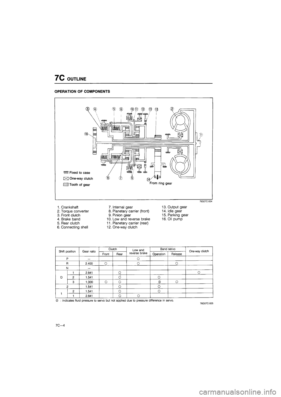
OPERATION OF COMPONENTS
76G07C-004
1. Crankshaft 7. Internal gear 13. Output gear
2. Torque converter 8. Planetary carrier (front) 14. Idle gear
3. Front clutch 9. Pinion gear 15. Parking gear
4. Brake band 10. Low and reverse brake 16. Oil pump
5. Rear clutch 11. Planetary carrier (rear)
6. Connecting shell 12. One-way clutch
Shift position Gear ratio Clutch Low and reverse brake
Band servo One-way clutch Shift position Gear ratio Front Rear
Low and reverse brake Operation Release One-way clutch
P — O
R 2.400 O o O
N —
D
1 2.841 O O
D 2 1.541 O O D
3 1.000 O o ® o
2 1.541 o o
1 2 1.541 0 0 1 1 2.841 0 o
® : Indicates fluid pressure to servo but not applied due to pressure difference in servo. 76G07C-005
7C-4
Page 1120 of 1865
7C OUTLINE
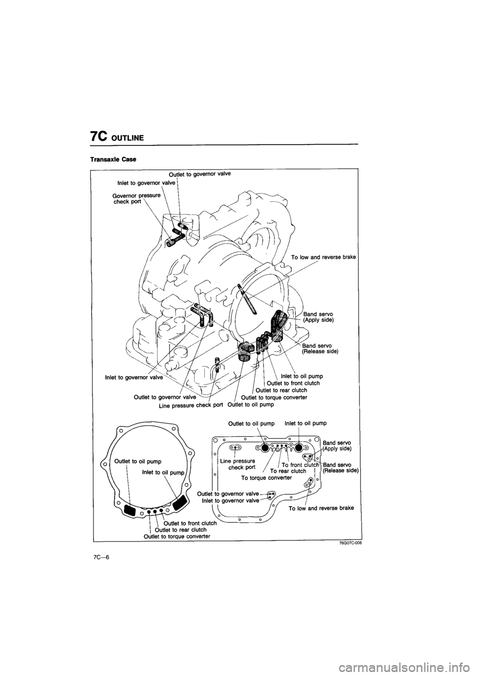
Transaxle Case
Outlet to governor valve
Inlet to governor valve'
Governor pressure
check port
To low and reverse brake
Band servo (Apply side)
Band servo (Release side)
Inlet to governor valve Inlet to oil pump
Outlet to front clutch
Outlet to rear clutch
Outlet to governor valve j Outlet to torque converter
Line pressure check port Outlet to oil pump
Outlet to oil pump Inlet to oil pump
Outlet to front clutch
Outlet to rear clutch
Outlet to torque converter
Band servo (Apply side)
Band servo (Release side)
Outlet to governor valve—
Inlet to governor valve
reverse brake
76G07C-008
7C—6
Page 1123 of 1865
TROUBLESHOOTING
7C
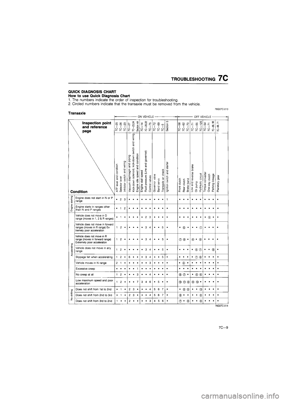
QUICK DIAGNOSIS CHART
How
to use
Quick Diagnosis Chart
1.
The
numbers indicate
the
order
of
inspection
for
troubleshooting.
2. Circled numbers indicate that
the
transaxle must
be
removed from
the
vehicle.
76G07C-013
Transaxle ON VEHICLE OFF VEHICLE
•
\ Inspection point
\
and
reference
\ page
Condition
7C-25
7C-26
7C-23
10—21
7C—23,24
Section
4A
7C-14
7C—20,22
10—lb
10-12 10—69
7C—5
Section
5
7C—58
7C-62
7C-70
7C-71
7C-55
7C-125
7C-54 7C-71
7C-66,
98
7C-68,
71
\ Inspection point
\
and
reference
\ page
Condition
ATF
level
and
condition
Selector
lever
Inhibitor
switch
and
wiring
^
Vacuum
diaphragm
and
piping
|
Kick-down
solenoid,
kick-down
switch
and
wiring
Engine
idle
speed
and
condition
Engine
stall
speed
Fluid
pressure
(Line
and
governor)
Control
valves
Governor
valve
Band
servo
Transaxle
air
check
Ignition
switch
and
starter
Front
clutch
Rear
clutch
Brake
band
Low
and
reverse
brake
Oil
pump Hydraulic
circuit
Torque
converter
One-way
clutch
Parking
linkage
Planetary
gear
I
Engine
starting
Engine does
not
start
in
N or P
range •
2 3
1
Engine
starting
Engine starts
in
ranges other than
N
and P
ranges •
1 2
Accelerating
Vehicle does
not
move
in
D
range (moves
in 1, 2 & R
ranges) •
• •
•
Accelerating
Vehicle does
not
move
in
forward ranges (moves
in R
range)
Ex-
tremely poor acceleration •
• 5
• •
© •
•
• ©
•
• •
•
Accelerating
Vehicle does
not
move
in R
range (moves
in
forward range) Extremely poor acceleration 1
2 •
•
• •
•
3 4
•
• 5
• ©
© •
©
• ©
•
• •
•
Accelerating
Vehicle does
not
move
in any
range 1
2 •
•
• •
•
3 4
•
• 5
• •
• •
•
© ©
•
• ©
•
Accelerating Slippage felt when accelerating 1
2 •
6
• •
•ST
CO
•
•
• 5
• •
• •
•
© ©
•
• •
• Accelerating
Vehicle moves
in
N
range
Accelerating
Excessive creep
Accelerating
No creep
at all
©
© •
•
© ©
•
• •
•
Accelerating
Low maximum speed
and
poor acceleration 1
2 •
•
• 7
3
4 6
•
5 •
• ©
© ©
No shifting
Does
not
shift from
1
st to 2nd
•
1 •
2
3 •
•
• 4
5
6 7
• •
© ©
•
• ©
•
• •
•
No shifting
Does
not
shift from
2nd to 3rd
•
1 •
2
3 •
•
• 4
5
6 7
•
No shifting
Does
not
shift from
3rd to 2nd
1
• •
2
• •
•
• 3
4
5 6
• ©
• ©
•
• ©
•
• •
•
76G07C-014
7C-9
Page 1124 of 1865
7C TROUBLESHOOTING
ON VEHICLE OFF VEHICLE
-
\ Inspection point
\ and reference
\ page
Condition
LO
(O
CO CJ OJ CM I
I I
O
O
CJ
r-~
r—
7C-27
7C—23,24
Section
4A
7C—14
7C—20,22
7C-75
CO
O)
I
I I
o
o o
r—
r—
Section
5
CO CO
o
WON I
I I
o
o o
1— 1—
m i-
in co
S
IO
i-
1
1 1
o
o o
—
I—
7C—54
7C-71
7C-66,
98
7C—68,
71
\ Inspection point
\ and reference
\ page
Condition
A.TF
level
and
condition
Selector
lever
Inhibitor
switch
and
wiring
Vacuum
diaphragm
and
piping
Kick-down
solenoid,
kick-down
switch
and
wiring
Engine
idle
speed
and
condition
Engine
stall
speed
Fluid
pressure
(Line
and
governor)
Control
valves
Governor
valve
Band
servo
Transaxle
air
check
Ignition
switch
and
starter
Front
clutch
Rear
clutch
Brake
band
Low
and
reverse
brake
Oil pump Hydraulic
circuit
Torque
converter
One-way
clutch
Parking
linkage
Planetary
gear
No
shifting
Does
not
shift from 2nd
to
1
st or from
3rd to
1
st 1
• •
2
• •
•
• 3
4
5 6
•
No
shifting
Does
not
kick-down when accelerator
is
depressed
in 3rd
within
the
kick-down range 1
• •
3
2*
•
• 4
5
• •
• •
• ©
•
• ©
•
• •
•
No
shifting
Excessive engine speed when accelerated
in 3rd
due
to
delayed kick-down 5
• 6
• ©
• •
•
• ©
•
• •
• No
shifting
Does
not
shift from
3rd to 2nd
on
D to
2
range shift 1
2 •
5
6 •
• ©
• ®
•
• ®
•
• •
•
No
shifting
Does
not
shift from
3rd to 2nd
on
D to 1
range shift 5
7 6
• ©
• ®
•
• ®
•
• •
•
Shift
shock
Excessive
N to
D
range shift shock •
• •
2
• 1
•
3 4
•
• •
• •
© •
•
• •
•
• •
•
Shift
shock
Excessive
1
st
to
2nd shift shock 1
• •
2
• •
3
• 4
•
5 6
• •
• ©
•
• •
•
• •
•
Shift
shock
Excissive 2nd
to 3rd
shift shock •
• •
1
• •
•
2 3
•
4 5
• ©
• ©
Shift
shock
Vehicle braked when shifted from
1
st
to 2nd
Shift
shock
Vehicle braked when shifted from 2nd
to 3rd
1
• •
•
• •
•
• 3
.
2 •
•
Shift
shock
Vehicle braked when shifted
to
R range 1
• •
•
• •
•
• •
•
3 2
• •
© ©
•
• •
•
• ©
•
Shift
shock
Shift shock felt when accelerator
is
released
and
deceleration occurs •
1 •
2
3*
•
4 5
6
• •
• •
• •
•
• ©
•
• *
•
Shift
shock
Excessively large 2nd
to 1st
shift shock
in 1
range 1
• •
2
• •
3
4 5
•
• •
•
Shift
point
Excessively high
1st to 2nd
and 2nd
to
3rd shift 1
• •
2
3 •
•
4 5
6
• •
•
Shift
point
Excessively high
3rd to 2nd
and
2nd to
1
st shift point •
1 •
2
3 •
•
4 5
6
• •
• •
• •
•
• ©
•
• •
•
Shift
point
Kick-down operates
or
engine overruns when depressing
ped-
al
in 3rd
beyond kick-down speed limit
1
2 •
3
• •
•
4 5
6
• 7
•
Shift
sequence
Shifts directly from 1st
to 3rd
1
• •
•
• •
•
• 2
3
• 4
• •
• ©
•
• ©
•
• •
•
Shift
sequence
Shifts from
2nd to 1st or
2nd
to
3rd
in
2
range •
1 •
•
• •
•
2 3
•
• •
•
7C-10