Brake MAZDA 626 1987 Workshop Manual
[x] Cancel search | Manufacturer: MAZDA, Model Year: 1987, Model line: 626, Model: MAZDA 626 1987Pages: 1865, PDF Size: 94.35 MB
Page 1154 of 1865
7C DISASSEMBLY
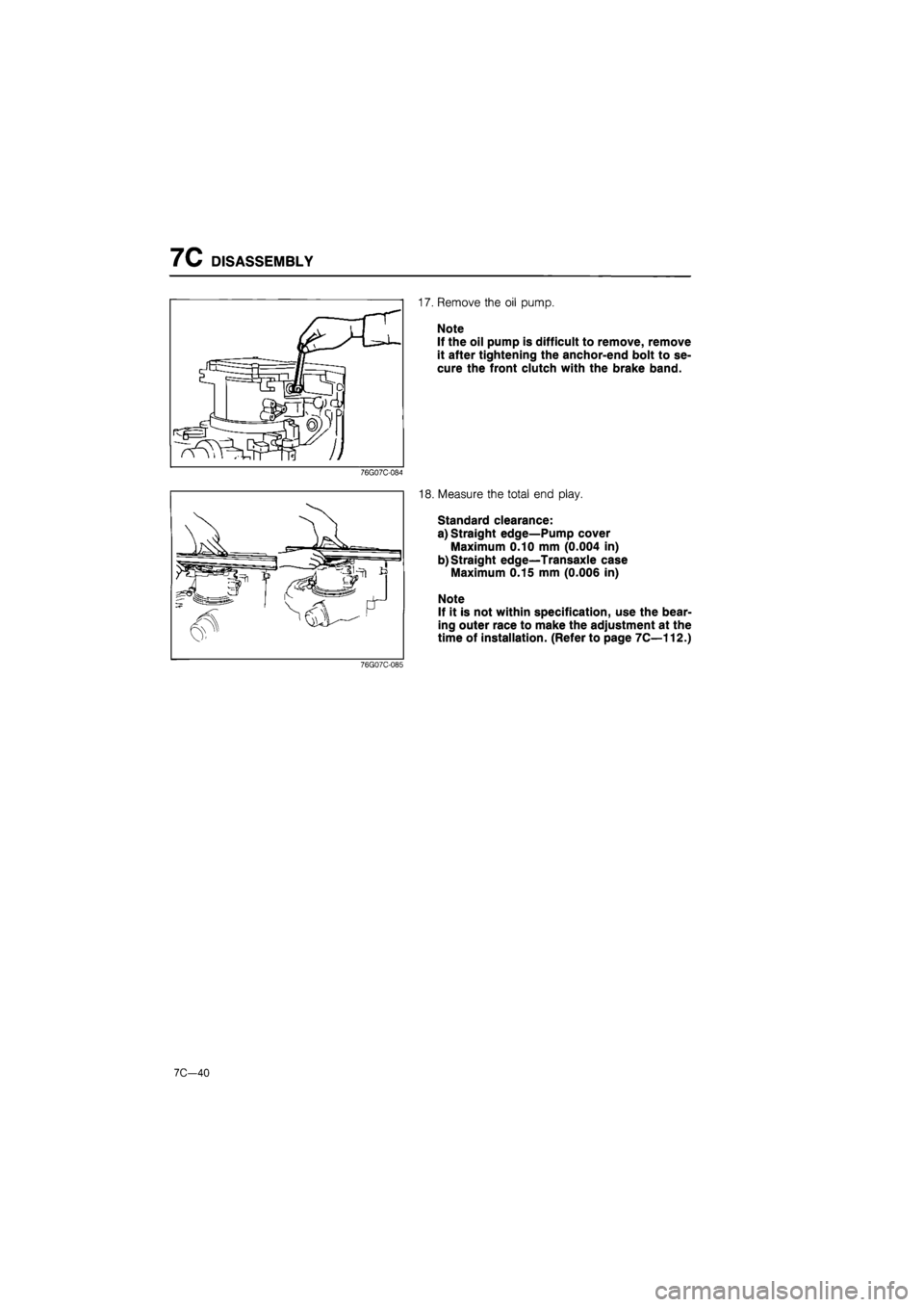
17. Remove the oil pump.
Note
If the oil pump is difficult to remove, remove
it after tightening the anchor-end bolt to se-
cure the front clutch with the brake band.
76G07C-084
18. Measure the total end play.
Standard clearance:
a) Straight edge—Pump cover
Maximum 0.10 mm (0.004 in)
b) Straight edge—Transaxle case
Maximum 0.15 mm (0.006 in)
Note
If it is not within specification, use the bear-
ing outer race to make the adjustment at the
time of installation. (Refer to page 7C—112.)
76G07C-085
7C-40
Page 1155 of 1865
DISASSEMBLY 7C
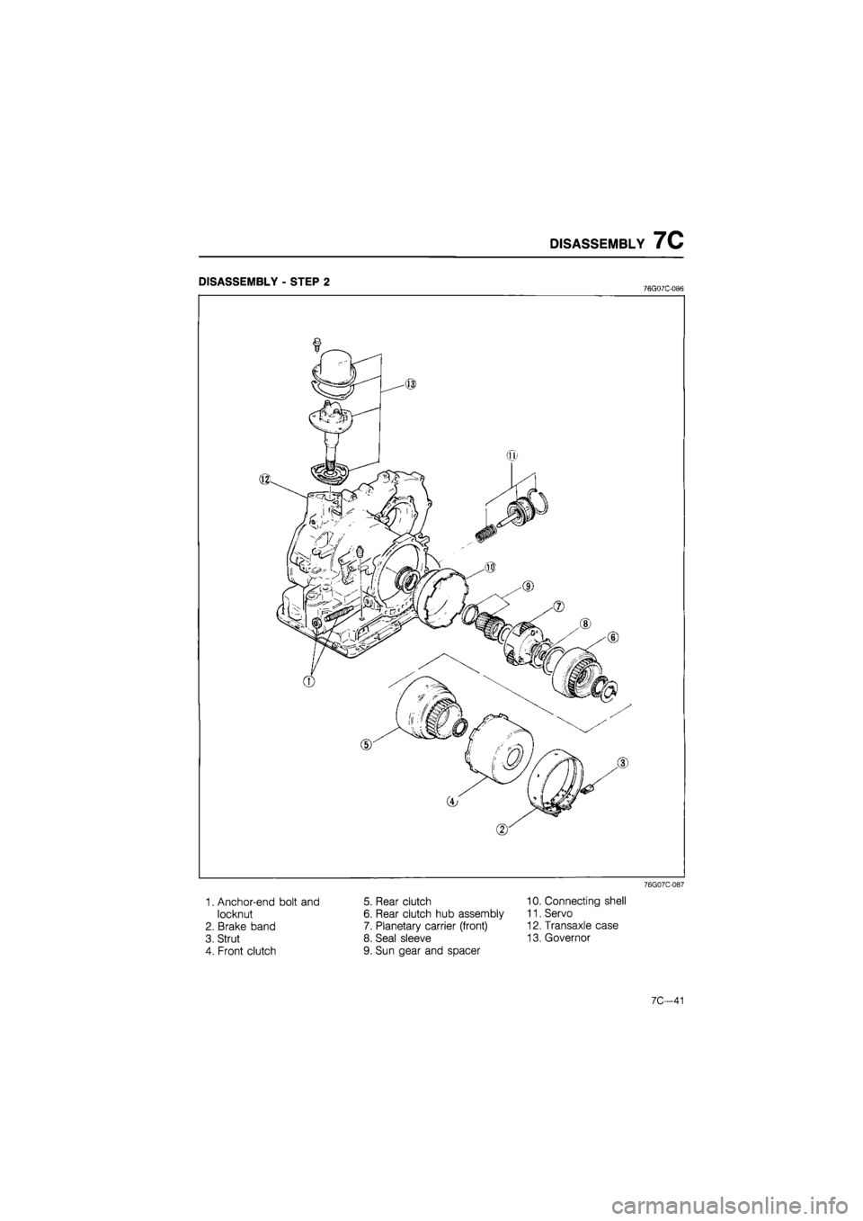
DISASSEMBLY - STEP 2 76G07C-086
76G07C-087
1. Anchor-end bolt and
locknut
2. Brake band
3. Strut
4. Front clutch
5. Rear clutch
6. Rear clutch hub assembly
7. Planetary carrier (front)
8. Seal sleeve
9. Sun gear and spacer
10. Connecting shell
11. Servo
12. Transaxle case
13. Governor
7C—41
Page 1156 of 1865
7C DISASSEMBLY
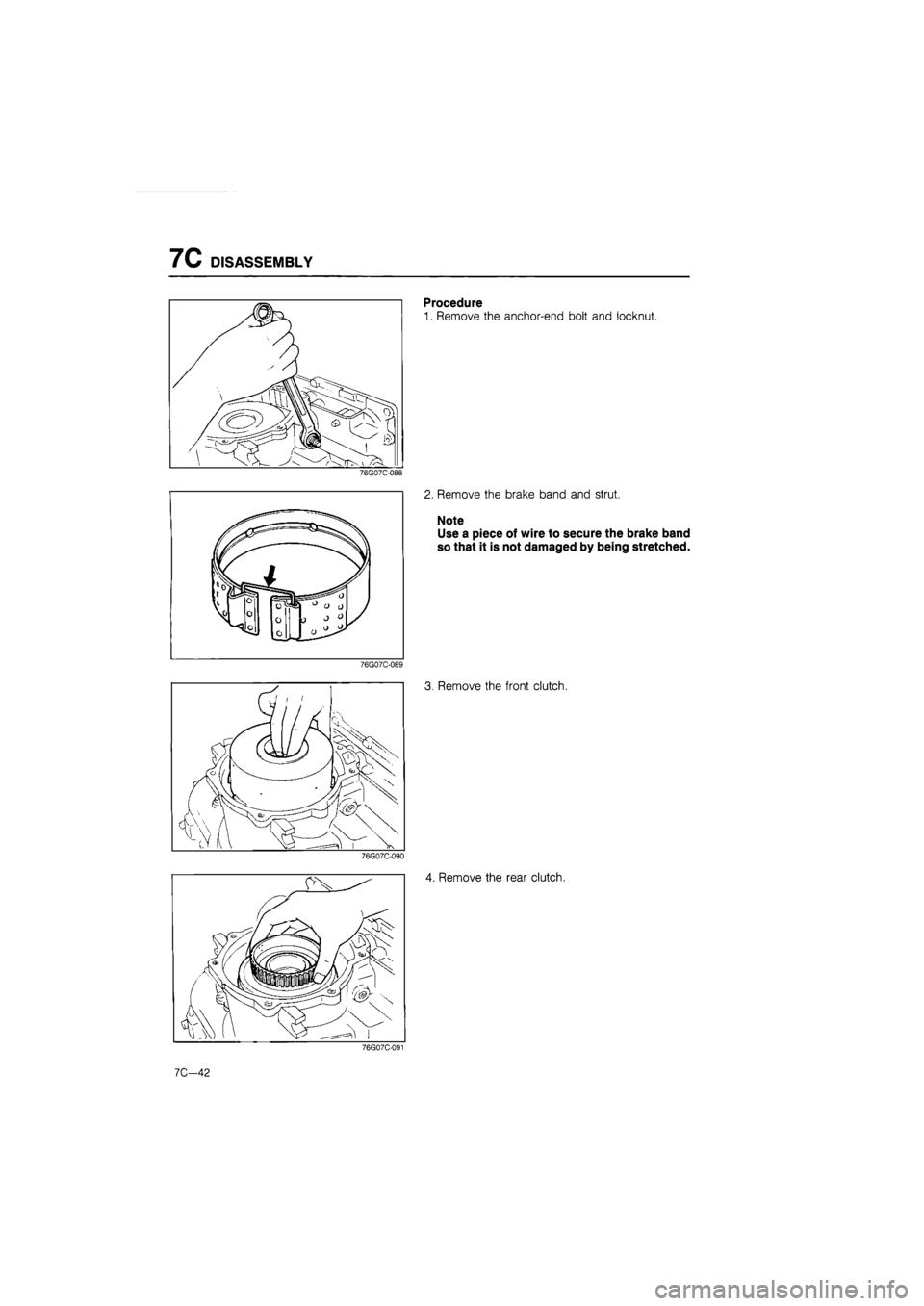
Procedure
1. Remove the anchor-end bolt and locknut.
76G07C-088
2. Remove the brake band and strut.
Note
Use a piece of wire to secure the brake band
so that it is not damaged by being stretched.
76G07C-089
3. Remove the front clutch.
76G07C-090
4. Remove the rear clutch.
76G07C-091
7C-42
Page 1159 of 1865
DISASSEMBLY 7C
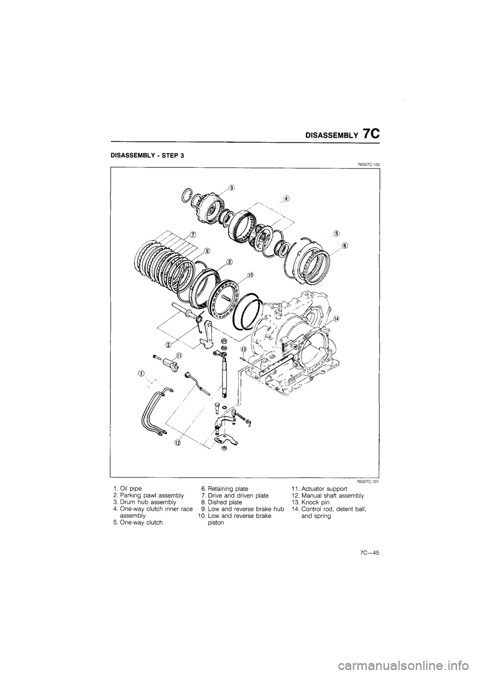
DISASSEMBLY - STEP 3
76G07C-100
1. Oil pipe
2. Parking pawl assembly
3. Drum hub assembly
4. One-way clutch inner race
assembly
5. One-way clutch
6. Retaining plate
7. Drive and driven plate
8. Dished plate
9. Low and reverse brake hub
10. Low and reverse brake
piston
76G07C-101
11. Actuator support
12. Manual shaft assembly
13. Knock pin
14. Control rod, detent ball,
and spring
7C—45
Page 1161 of 1865
DISASSEMBLY 7C
76G07C-106
76G07C-107
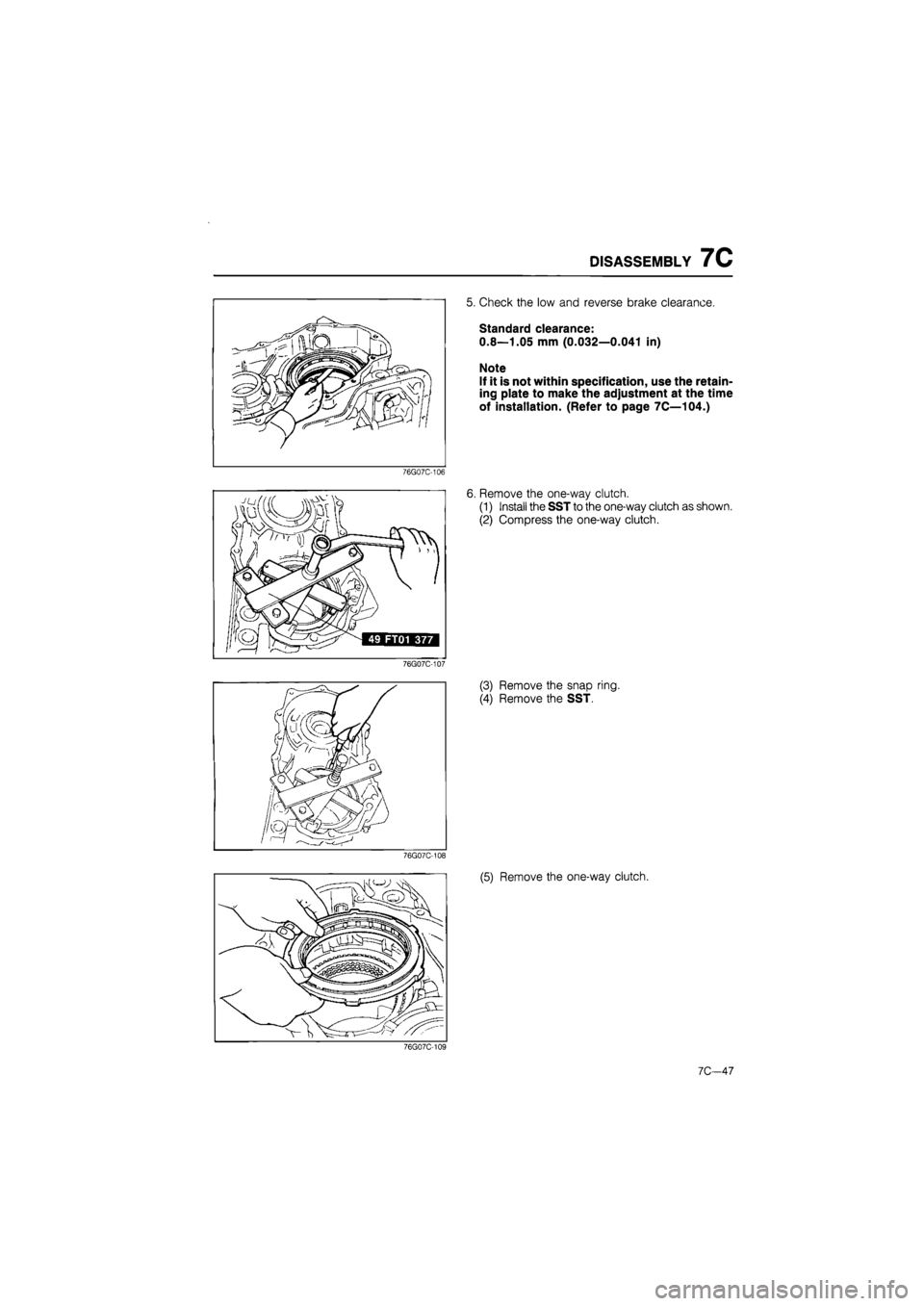
5. Check the low and reverse brake clearance.
Standard clearance:
0.8—1.05 mm (0.032—0.041 in)
Note
If it is not within specification, use the retain-
ing plate to make the adjustment at the time
of installation. (Refer to page 7C—104.)
6. Remove the one-way clutch.
(1) Install the SST to the one-way clutch as shown.
(2) Compress the one-way clutch.
(3) Remove the snap ring.
(4) Remove the SST.
76G07C-108
(5) Remove the one-way clutch.
76G07C-109
7C—47
Page 1162 of 1865
7C DISASSEMBLY
76G07C-110
76G07C-111
76G07C-112
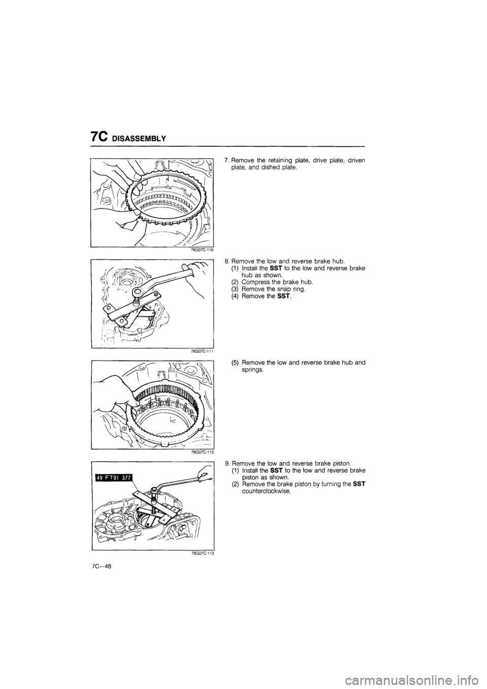
7. Remove the retaining plate, drive plate, driven
plate, and dished plate.
8. Remove the low and reverse brake hub.
(1) Install the SST to the low and reverse brake
hub as shown.
(2) Compress the brake hub.
(3) Remove the snap ring.
(4) Remove the SST.
(5) Remove the low and reverse brake hub and
springs.
9. Remove the low and reverse brake piston.
(1) Install the SST to the low and reverse brake
piston as shown.
(2) Remove the brake piston by turning the SST
counterclockwise.
76G07C-113
7C—48
Page 1168 of 1865
7C INSPECTION AND REPAIR
INSPECTION AND REPAIR
PRECAUTION
(1) Several of the parts resemble each other; organize them so that they do not get mixed up.
(2) Clean each part with cleaning oil, clean out the oil holes and oil passages with compressed air,
and check that there are no obstructions.
(3) When using cleaning oil and compressed air, wear protective eyewear.
(4) If a clutch plate or brake band is replaced with a new one, soak it in ATF for 2 hours or more
before installing.
(5) Before assembly, apply ATF to all seal rings, rotating parts, and sliding parts.
(6) All seals, gaskets and roll pins must be replaced with new ones during assembly.
(7) Use petroleum jelly, not grease where required.
(8) When it is necessary to replace a bushing, replace the assembly which includes that bushing.
76G07C-353
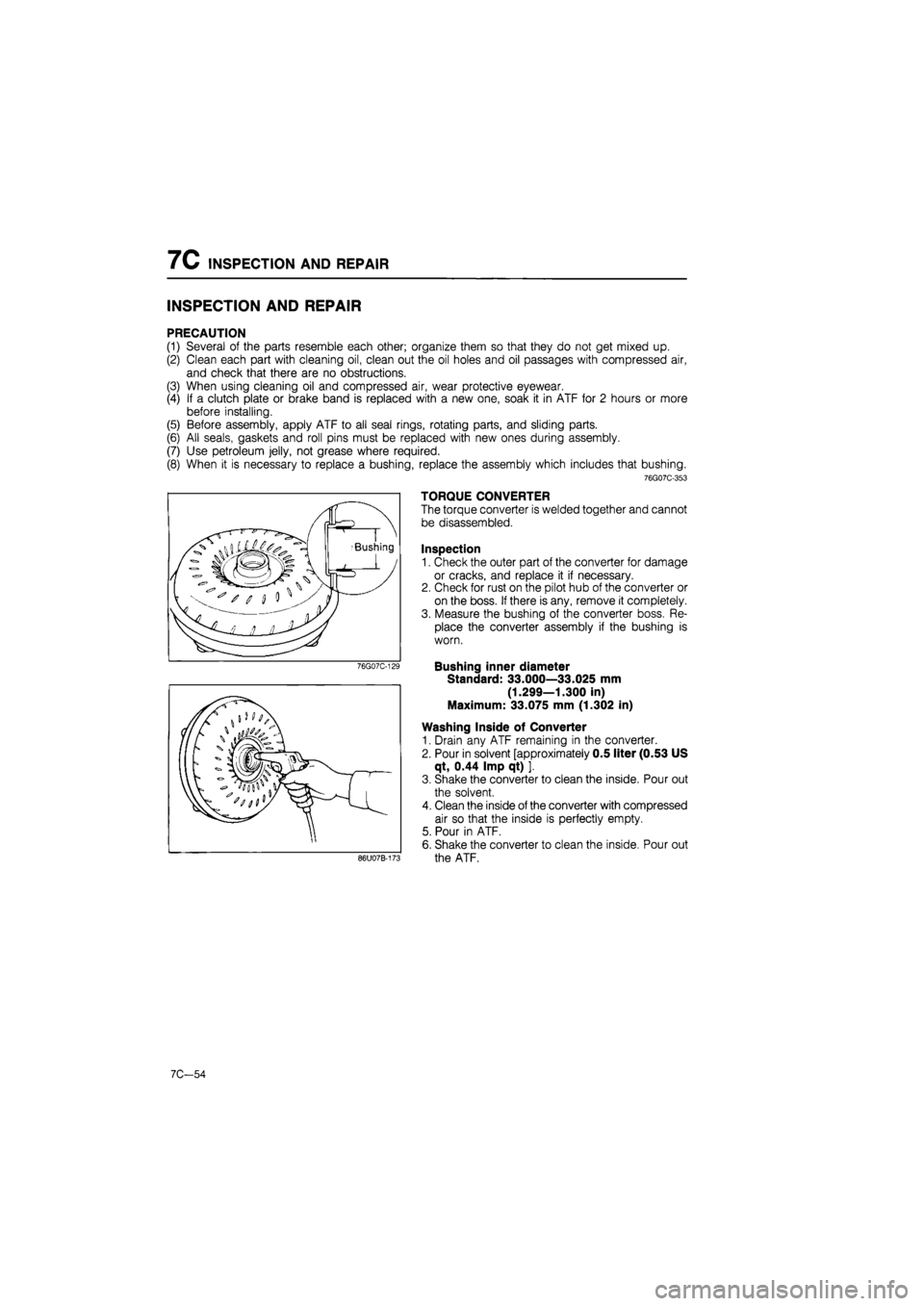
TORQUE CONVERTER
The torque converter is welded together and cannot
be disassembled.
Inspection
1. Check the outer part of the converter for damage
or cracks, and replace it if necessary.
2. Check for rust on the pilot hub of the converter or
on the boss. If there is any, remove it completely.
3. Measure the bushing of the converter boss. Re-
place the converter assembly if the bushing is
worn.
Bushing inner diameter
Standard: 33.000—33.025 mm
(1.299—1.300 in)
Maximum: 33.075 mm (1.302 in)
Washing Inside of Converter
1. Drain any ATF remaining in the converter.
2. Pour in solvent [approximately 0.5 liter (0.53 US
qt, 0.44 Imp qt) ].
3. Shake the converter to clean the inside. Pour out
the solvent.
4. Clean the inside of the converter with compressed
air so that the inside is perfectly empty.
5. Pour in ATF.
6. Shake the converter to clean the inside. Pour out
the ATF.
7C-54
Page 1184 of 1865

7C INSPECTION AND REPAIR
76G07C-181
Mr
76G07C-182
76G07C-183
Inspection
Check the following and replace any faulty parts.
1. Damaged or worn piston
2. Weakened return spring
Free length of spring:
FE engine: 48.0 mm (1.89 in)
F6 engine: 45.5 mm (1.79 in)
Assembly
1. Apply ATF to the inner and outer seal rings, and
install them onto the servo piston.
2. Apply ATF to the seal ring, and install it onto the
servo retainer.
3. Assemble the servo retainer and servo piston.
BRAKE BAND
Inspection
Check the following and replace any faulty part.
1. Damaged or worn brake band
76G07C-184
7C-70
Page 1185 of 1865

INSPECTION AND REPAIR 7C
76G07C-185
76G07C-186
76G07C-187
PLANETARY CARRIER (FRONT)
Inspection
Check the following and replace any faulty parts.
1. Rotation of pinion gear
2. Clearance between pinion washer and planetary
carrier
Clearance: 0.8 mm (0.031 in) max.
ONE-WAY CLUTCH
Inspection
Check the following and replace any faulty parts.
1. One-way clutch operation
(1) Install the one-way clutch into the one-way
clutch inner race.
(2) Make sure that when the one-way clutch is held
and the inner race is turned, the clutch turns
smoothly in one direction only.
2. Worn bushing
Bushing inner diameter:
130.063 mm (5.121 in) max.
76G07C-188
LOW AND REVERSE BRAKE
Inspection
Check the following and replace any faulty parts.
1. Damaged or worn drive and driven plates
Drive plate thickness
Standard: 1.6 mm (0.063 in)
Minimum: 1.4 mm (0.055 in)
2. Broken or worn snap ring
3. Deformed low and reverse brake hub
4. Broken or weakened spring
Free length of spring:
27.7 mm (1.091 in)
5. Damaged or worn piston
6. Damaged seal contact area of transaxle case
7C-71
Page 1189 of 1865

INSPECTION AND REPAIR 7C
CONTROL VALVE BODY
Precaution
(1) Pay close attention when handling the control valve because it consists of the most precise and
delicate parts of the transaxle.
(2) Neatly arrange the removed parts in order to avoid mixing up similar parts.
(3) Disassemble the control valve assembly and thoroughly clean it when the clutch and/or brake
bands are burned, and/or when the automatic transaxle fluid is degenerated.
Disassembly
Disassemble in the sequence shown in the figure.
2.5—3.4 N m _ (25—35 cm-kg, (7) 22—30 in-lb)
2.5—3.4 N-m (25—35 cm-kg 22—30 in-lb)
. 2.5—3.4 N-m (25—35 cm-kg, 22—30 In-lb)
2.5—3.4 N-m (25—35 cm-kg, 22—30 in-lb)
5—7 N-m {50—70 cm-kg, 43—61 In-lb)
2.5—3.4 N-m (25—35 cm-kg, 22—30 in-lb)
2.5—3.4 N-m (25—35 cm-kg, 22—30 in-lb)
5—7 N-m (50—70 cm-kg, 43—61 in-lb)
^ - 3—4 N-m (30—40 cm-kg, 26—35 in-lb)
76G07C-201
1. Manual valve
2. Oil strainer
3. Lower body
4. Separator plate
5. Throttle relief ball and
spring
6. Orifice check valve and
spring
7. Sub-body
8. Orifice check valve
9. Side plate
10. Vacuum throttle valve
11. Spring
12. Throttle backup valve
13. Downshift valve
14. Spring
15. Side plate
16. Modifier valve
17. 2-3 shift valve
18. Spring
19. 2-3 shift plug
20.1-2 shift valve
21. Spring
22. Side plate
23. Spring
24. Second lock valve
25. Pressure regulator sleeve
26. Pressure regulator plug
27. Spring seat
28. Spring
29. Pressure regulator valve
30. Upper body
7C-75