torque MAZDA 626 1987 Workshop Manual
[x] Cancel search | Manufacturer: MAZDA, Model Year: 1987, Model line: 626, Model: MAZDA 626 1987Pages: 1865, PDF Size: 94.35 MB
Page 805 of 1865

CLUTCH AND FLYWHEEL 6
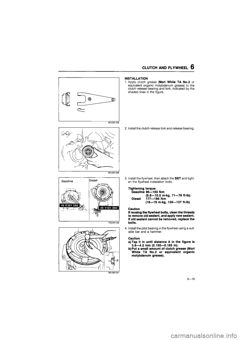
INSTALLATION
1. Apply clutch grease (Mori While TA No.2 or
equivalent organic molybdenum grease) to the
clutch release bearing and fork, indicated by the
shaded lines in the figure.
86U06X-038
2. Install the clutch release fork and release bearing.
86U06X-039
Gasoline Diesel
}
.iSlf
49 E301 060 g^M 1/ j> •«] 49 V101 060
76G06X-026
3. Install the flywheel, then attach the SST and tight-
en the flywheel installation bolts.
Tightening torque:
Gasoline 96—103 N-m
(9.8—10.5 m-kg, 71—76 ft-lb)
Diesel 177—186 N-m
(18—19 m-kg, 130—137 ft-lb)
Caution
If reusing the flywheel bolts, clean the threads
to remove old sealant, and apply new sealant.
If old sealant cannot be removed, replace the
bolts.
4. Install the pilot bearing in the flywheel using a suit-
able bar and a hammer.
Caution
a) Tap it in until distance A in the figure is
3.8—4.2 mm (0.150—0.165 in).
b) Put a small amount of clutch grease (Mori
White TA No.2 or equivalent organic
molybdenum grease).
86U06X-041
6—19
Page 806 of 1865

6 CLUTCH AND FLYWHEEL
86U06X-042
86U06X-043
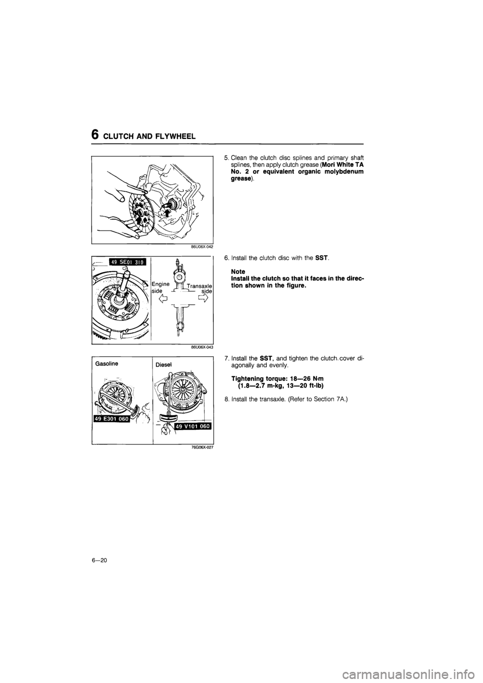
5. Clean the clutch disc splines and primary shaft
splines, then apply clutch grease (Mori White TA
No. 2 or equivalent organic molybdenum
grease).
6. Install the clutch disc with the SST.
Note
Install the clutch so that it faces in the direc-
tion shown in the figure.
7. Install the SST, and tighten the clutch, cover di-
agonally and evenly.
Tightening torque: 18—26 N-m
(1.8—2.7 m-kg, 13—20 ft-lb)
8. Install the transaxle. (Refer to Section 7A.)
76G06X-027
6-20
Page 814 of 1865

7A ON-VEHICLE MAINTENANCE
86U07A-012
86U07A-013
86U07A-014
8. Tap the new oil seal into the transaxle case with
the SST.
Note
a) Tap in until the oil seal installer contacts the
case.
b)Coat the oil seal lip with transaxle oil.
9. Replace the driveshaft end clip with a new one.
Insert the clip with the gap at the top of the groove.
10. Install the driveshaft as follows:
(1) Pull the front hub outward, then
fit
the driveshaft
into the transaxle.
(2) Insert the driveshaft into the transaxle by push-
ing on the wheel hub assembly.
Note
a) Be careful not to damage the oil seal.
b) After installation is finished, pull the front
hub slowly outward to check that the
driveshaft is held securely by the clip.
11. Install the lower arm ball-joint to the knuckle, and
tighten the clinch bolt.
Tightening torque:
43—54 N-m (4.4—5.5 m-kg, 32—40 ft-lb)
12. Install the tie-rod end and new cotter pin.
Tightening torque:
29—44 N m (3.0—4.5 m-kg, 22—33 ft-lb)
86U07A-015
7 A—8
Page 815 of 1865

ON-VEHICLE MAINTENANCE 7A
13. Adjust and tighten the stabilizer.
Tightening torque:
16—23 Nm (1.6—2.3 m-kg, 12—17 ft-lb)
Dimension: 20.1 mm (0.79 in)
86U07A-016
76G07A-007
14. Install the drain plug.
Tightening torque:
39—59 Nm (4.0—6.0 m-kg, 29—43 ft-lb)
15. Install the wheel.
Tightening torque:
88—118 Nm (9.0—12.0 m-kg, 65—87 ft-lb)
16. Add the correct quantity of the specified oil.
Type: A.T.F.: DEXRON II
Above -18°C (0°F):
API: GL-4 or GL-5
SAE 80W-90 or SAE 90
Capacity: 3.35 liters (3.6 US qt, 3.0 Imp qt)
7A—9
Page 842 of 1865

7A ASSEMBLY
STEP 3
Torque specifications
7A—36
Page 844 of 1865

7 A ASSEMBLY
Outer race
Selector
76G07A-032
i "k
49 G030 381
49 G030 382A
49 G030 382A
76G07A-033
1. Install the primary and secondary shaft bearing out-
er races into the transaxle case (diaphragm springs
and shims removed).
2. After mounting the clutch housing onto the trans-
axle hanger, and set the differential bearing outer
race into the clutch housing, and tap in with a ham-
mer until it contacts the clutch housing, and tap
in with a hammer until it contacts the clutch
housing.
3. Assemble the outer races into the SST (selector)
as shown in the figure.
Note
Turn the selector to eliminate the gap indicat-
ed by the arrow in the figure.
4. Set the differential assembly onto the clutch hous-
ing, then mount the bearing outer race and the
selector on the differential.
Set the assembled selectors for the primary and
secondary shaft in the clutch housing.
Mount the shaft gear assemblies as shown in the
figure.
5. Set the SST (collars) in the positions shown in the
figure.
76G07A-034
6. Install the transaxle case then tighten the SST(bolts)
to the specified torque.
Tightening torque:
37—52
N
m (3.8—5.3 m-kg, 27—38 ft—lb)
76G7A-035
7A-38
Page 848 of 1865

7 A ASSEMBLY
86U07A-106
86U07A-107
86U07A-108
8. Install the new breather.
9. Install the new change rod oil seal.
10. Install the change rod ©, the boot the spring
(3),
the reverse gate @, and selector ©, as shown.
11. Install the new roll pin.
12. Install the change arm.
Tightening torque: 12—14 N-m
(120—140 cm-kg, 104—122 in-lb)
13. Install the guide plate.
Tightening torque:
©8—11 N-m
(80—115 cm-kg, 69—100 in-lb)
(1)22—33 N-m
(2.25—3.35 m-kg, 16—25 ft-lb)
14. Install reverse lever, and reverse lever shaft.
15. Install the new roll pin.
16. Install the speedometer driven gear assembly.
86U07A-109
7A-42
Page 849 of 1865

ASSEMBLY 7A
76G07A-044
76G07A-045
Bearing Preload
Check the shaft gears and the differential bearing
preload.
Note
a) Check that the correct adjust shims were
selected.
b) If the bearing preload is not within specifi-
cation, adjust again.
1. Set the primary shaft gear and the differential into
the clutch housing.
2. Install the transaxle case, and tighten to the speci-
fied torque.
Tightening torque: 37—52 N-m
(3.8—5.3 m-kg, 27—38 ft-lb)
3. Connect the SST and install it through the
driveshaft hole.
4. Measure the preload.
Preload: 1.4—2.0 N-m
(14—20 cm-kg, 12.1—17.3 in-lb)
5. Remove the SST.
6. Install the SST to the primary shaft gear.
7. Measure the preload.
Preload: 0.1—0.25 N-m
(1.0—2.5 cm-kg, 0.87—2.18 in-lb)
76G07A-046
8. Remove the SST, transaxle case, primary shaft
gear and differential.
9. Install the secondary shaft gear and transaxle case
then tighten to the specified torque.
Tightening torque: 37—52 N-m
(3.8—5.3 m-kg, 27—38 ft-lb)
10. Check the secondary shaft preload with the SST.
Preload: 0.2—0.4 N-m
(2.0—4.0 m-kg, 1.7—3.4 in-lb)
76G07A-047
7A-43
Page 850 of 1865

7A ASSEMBLY
STEP 4
Torque Specifications
37—52 N-m (3.8—5.3 m-kg, 27—38 tt-lb)
15—21 Km (150—210 cm-kg, 129-181 In-lb)
8—11 Nm (80—110 cm-kg, 68—95 in-lb)
86U07A-110
7A—44
Page 852 of 1865

7A ASSEMBLY
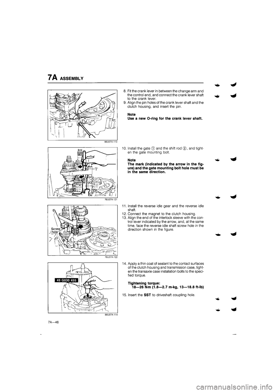
8. Fit the crank lever in between the change arm and
the control end, and connect the crank lever shaft
to the crank lever.
9. Align the pin holes of the crank lever shaft and the
clutch housing, and insert the pin.
Note
Use a new O-ring for the crank lever shaft.
86U07A-113
10. Install the gate © and the shift rod ©, and tight-
en the gate mounting bolt.
Note
The mark (indicated by the arrow in the fig-
ure) and the gate mounting bolt hole must be
in the same direction.
76U07A-121
11. Install the reverse idle gear and the reverse idle
shaft.
12. Connect the magnet to the clutch housing.
13. Align the end of the interlock sleeve with the con-
trol lever indicated by the arrow, and, at the same
time, face the reverse idle shaft screw hole in the
direction shown in the figure.
76U07A-122
14. Apply a thin coat of sealant to the contact surfaces
of the clutch housing and transmission case, tight-
en the transaxle case installation bolts to the speci-
fied torque.
Tightening torque:
18—26 N m (1.8—2.7 m-kg, 13—18.8 ft-lb)
15. Insert the SST to driveshaft coupling hole.
7A-46