check engine light MAZDA 626 1987 User Guide
[x] Cancel search | Manufacturer: MAZDA, Model Year: 1987, Model line: 626, Model: MAZDA 626 1987Pages: 1865, PDF Size: 94.35 MB
Page 458 of 1865

CONTROL SYSTEM 4 A
76G04A-176
76G04A-177
76G04A-178
Replacement
1. Disconnect the negative battery cable.
2. Remove the front console covers (right or left).
3. Disconnect the connectors from the control unit.
4. Remove and replace the control unit.
INHIBITOR SWITCH
Inspection
1. Verify that the starter operates with the ignition
switch at START position in
P
and N positions only.
2. Check that the back-up lights illuminate when R
position selected and the ignition switch is ON.
3. If not as specified, check the following:
(1) Jack up the vehicle and support it with safety
stands.
(2) Disconnect the inhibitor switch connector.
(3) Check continuity of the switch with an
ohmmeter.
Connecting guide
Position
N
D,1,2
Connector terminal
O -O
O
O
-O
-O
O—O: indicates continuity
4. Replace if necessary.
IDLE SWITCH
Inspection
1. Warm up the engine and run it at idle.
2. Turn all accessories OFF.
3. Connect a tachometer to the engine.
4. Connect a voltmeter to the carburetor connector
F terminal.
76G04A-179
4A-93
Page 487 of 1865

SWITCH MONITOR FUNCTION 4B
SWITCH MONITOR FUNCTION
Individual switches can be monitored by the SST.
Note
The test connector must be grounded and the ignition switch ON (engine stopped).
Control unit
76G04B-022
Switch Self-Diagnosis Checker (Monitor lamp) Remarks Switch Light ON Light OFF Remarks
Clutch switch Pedal released Pedal depressed Gear:
IN
Neutral switch In gear Neutral Clutch pedal released
Idle switch Pedal depressed Pedal released
—
Brake light switch Pedal depressed Pedal released
—
A/C switch ON OFF Blower motor position:
"1"
position
Headlight switch ON OFF
—
Rear defroster switch ON OFF
—
Blower switch ON OFF Blower motor position:
"3"
or
"4"
position
Inhibitor switch D,
1, 2
and
R
range P and
N
range
—
Water thermo switch (Elec-trical fan) Terminal disconnected Terminal connected While fan
not
operating
4B-25
Page 502 of 1865

4B IDLE-UP SYSTEM
76G04B-052
76G04B-053
76G04B-054
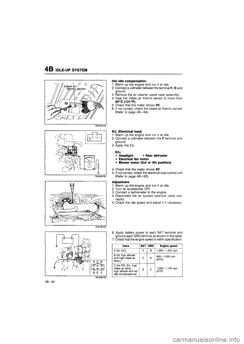
Hot idle compensation
1. Warm up the engine and run it at idle.
2. Connect a voltmeter between the terminal F, D and
ground.
3. Remove the air cleaner upper case assembly.
4. Heat the intake air thermo sensor to more than
55°C
(131
°F).
5. Check that the meter shows OV.
6. If not correct, check the intake air thermo sensor
(Refer to page 4B—94).
E/L (Electrical load)
1. Warm up the engine and run it at idle.
2. Connect a voltmeter between the F terminal and
ground.
3. Apply the E/L.
E/L:
• Headlight • Rear defroster
• Electrical fan motor
• Blower motor (3rd or 4th position)
4. Check that the meter shows OV.
5. If not correct, check the electrical load control unit
(Refer to page 4B—93).
Adjustment
1. Warm up the engine and run it at idle.
2. Turn all accessories OFF.
3. Connect a tachometer to the engine.
4. Disconnect the air bypass solenoid valve con-
nector.
5. Check the idle speed and adjust it if necessary.
6. Apply battery power to each BAT terminal and
ground each GRD terminal as shown in the table.
7. Check that the engine speed is within specification.
76G04B-055
Valve BAT GRD Engine speed
A (for A/C) A B 1,250—1,350
rpm
B (for high altitude and high intake
air
temp.) C D 900—1,000
rpm
(MTX)
1,000-1,100
rpm
(ATX)
C (for P/S, E/L, high intake
air
temp., high altitude and
hot
idle compensations)
E F
900—1,000
rpm
(MTX)
1,000-1,100
rpm
(ATX)
4B—40
Page 542 of 1865

4B PCV SYSTEM
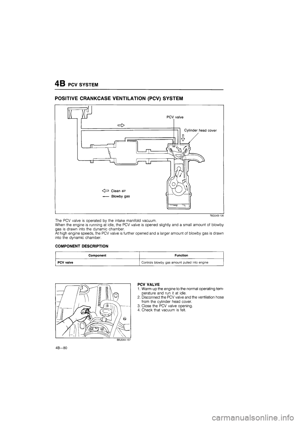
POSITIVE CRANKCASE VENTILATION
(PCV)
SYSTEM
76G04B-106
The PCV valve is operated by the intake manifold vacuum.
When the engine is running at idle, the PCV valve is opened slightly and a small amount of blowby
gas is drawn into the dynamic chamber.
At high engine speeds, the PCV valve is further opened and a larger amount of blowby gas is drawn
into the dynamic chamber.
COMPONENT DESCRIPTION
Component Function
PCV valve Controls blowby gas amount pulled into engine
PCV VALVE
1. Warm up the engine to the normal operating tem-
perature and run it at idle.
2. Disconnect the PCV valve and the ventilation hose
from the cylinder head cover.
3. Close the PCV valve opening.
4. Check that vacuum is felt.
4B—80
Page 550 of 1865

4B CONTROL SYSTEM
Terminal Voltage
If the input and output devices and related wiring are normal, but the engine control unit terminal volt-
age is incorrect, replace the engine control unit.
Terminal Input Output Connection to Voltage (After warming-up) Remarks Terminal Input Output Connection to IGN: ON Idle Remarks
1A — — — — —
1B o Self-Diagnosis Checker (Code number)
For 3sec. after ignition switch OFF ->• ON: below 6.2V (Buzzer sounds) After 3sec.: Battery voltage (Buzzer does not sound)
• Using Self-Diagnosis Check-er and test con-nector grounded • Buzzer sounds: below 6.2V • Buzzer does not sound: Battery voltage
1C — — — — —
1D o Self-Diagnosis Checker (Monitor lamp)
Test connector grounded
For 3sec. after igni-tion switch OFF ON:
below 6.2V (light il-luminates) After 3sec.: Battery voltage (light does not illuminate)
(Test connector grounded) approx. 10V (Test connector not grounded) Monitor lamp ON: below 6.2V Monitor lamp OFF: Battery voltage
With Self-Diagnosis
Checker
1E O Idle switch Accelerator pedal released: below 1.5V
Accelerator pedal depressed: Battery voltage
1F o A/C relay A/C switch ON: below 2.5V A/C switch OFF: Battery voltage
Blower motor ON
1G — — — — —
1H o Water thermo switch Below 1,5V Radiator temp.:
above 17°C (63°F)
11 o Electrical load con-trol unit Electrical load ON: below 1.5V Electrical load OFF: Battery voltage Electrical load: Rear defroster Headlight Blower motor (3rd & 4th position) Electrical fan
1J o Brake light switch Brake pedal released: below 1.5V
Brake pedal depressed: battery voltage
1K — — — — — —
1L o A/C switch A/C switch ON: below 1.5V
A/C switch OFF: battery voltage
Blower motor: ON
1M o Ignition coil © terminal Battery voltage *1 Battery voltage *1 Engine Signal Monitor: green and red lights flash
1N — — — — —
10 — — — —
4B-88
Page 555 of 1865

4B CONTROL SYSTEM
E/L CONTROL UNIT
Inspection
1. Connect a voltmeter between the E/L control unit
and ground.
2. Start the engine and check the terminal voltages
as described below.
69G04A-174
Terminal Input Output Connection to Voltage (after warm-up) Remarks Terminal Input Output Connection to Ignition switch: ON idle Remarks
A
(BW) — — Ignition switch Battery voltage
B — — — — — —
C
(B) — — Ground OV
D (LY) 0 Electrical fan relay
Battery voltage Coolant temp.: below 97°C (207°F) D (LY) 0 Electrical fan relay
Below 1,5V Coolant temp.:
above 97°C (207°F)
E
(GY) o Engine control unit
(11)
OV E/L: ON E
(GY) o Engine control unit
(11) Battery voltage E/L: OFF
F (RB) 0 Headlight switch
Battery voltage Headlight switch:
ON F (RB) 0 Headlight switch
Below 1,5V Headlight switch:
OFF
G (LB) 0 Blower motor switch
Below 1,5V Blower motor switch: ON (3rd or 4th position) G (LB) 0 Blower motor switch
Approx. 5V Others
H
(BL) 0 Rear defroster switch
Below 1,5V Rear defroster switch: ON H
(BL) 0 Rear defroster switch Battery voltage Rear defroster switch: OFF
76G04B-131
Replacement
1. Remove the engine control unit. (Refer to page
4B-91)
2. Replace the E/L control unit.
3. Install in the reverse order of removal.
4B—93
Page 574 of 1865

TROUBLESHOOTING WITH SST 4C
49 H018 9A1
negative battery cable
^ll
Test connector: (Green, 1 pin)
86U04A-015
Ignition switch:
ON
for six
seconds
76G04C-014
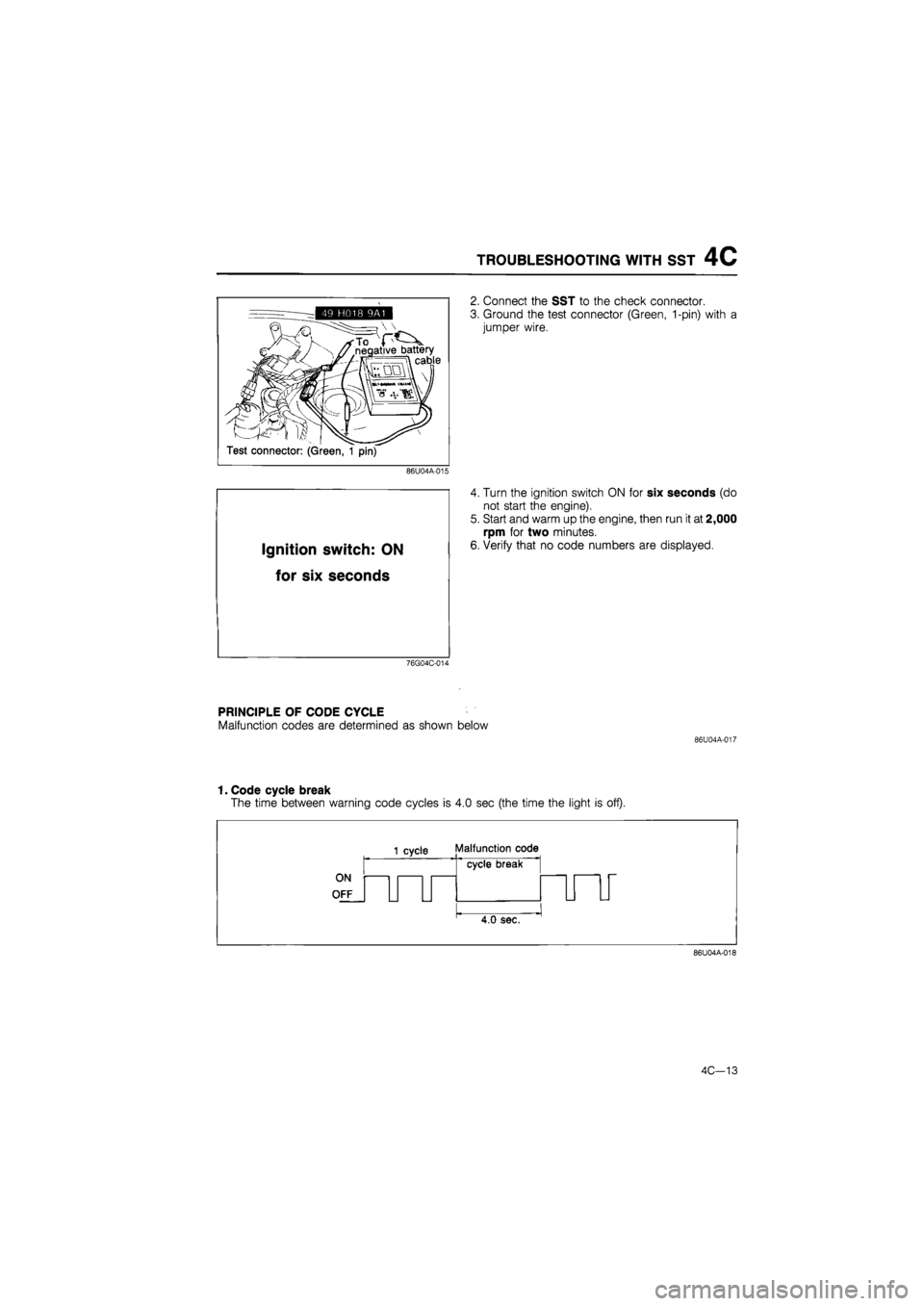
2. Connect the SST to the check connector.
3. Ground the test connector (Green, 1-pin) with a
jumper wire.
4. Turn the ignition switch ON for six seconds (do
not start the engine).
5. Start and warm up the engine, then run it at 2,000
rpm for two minutes.
6. Verify that no code numbers are displayed.
PRINCIPLE OF CODE CYCLE
Malfunction codes are determined as shown below
86U04A-017
1. Code cycle break
The time between warning code cycles is 4.0 sec (the time the light is off).
ON
OFF
1 cycle Malfunction code
cycle break
4.0 sec.
86U04A-018
4C—13
Page 586 of 1865

SWITCH MONITOR FUNCTION 4C
SWITCH MONITOR FUNCTION
Individual switches can be monitored by the SST (Self-Diagnosis checker 49 G018 9A0 or Digital
code checker 49 9200 180).
Note
The test connector must be grounded and the ignition switch ON (engine stopped).
Engine control unit
76G04C-035
Switch Self-Diagnosis Checker (Monitor lamp) Remark Switch Light ON Light OFF Remark
Clutch switch Pedal released Pedal depressed In gear
Neutral switch In gear Neutral Clutch pedal released
Idle switch Pedal depressed Pedal released —
Headlight switch ON OFF —
Rear defroster switch ON OFF —
Blower switch ON OFF Blower motor position: "3" or "4"
Water thermo switch (Elec-trical fan) Terminal disconnected Terminal connected While fan not operating
4C—25
Page 608 of 1865

ISC SYSTEM 4C
76G04C-081
76G04C-082
Cooling fan switch
Rear defroster switch
Head light switch
Blower motor switch
ISC "valve
76G04C-083
(ISC valve)
6. Connect the ISC valve connector.
Note
a) Make sure that the initial idle speed is set
to specification.
b) All accessory must be OFF.
7. Again disconnect the ISC valve connector (engine
at normal operating temperature).
8. Check that the engine speed decreases.
9. Reconnect the ISC valve connector.
10 Remove the jumper wire from the test connector
and make sure that the idle speed is within specifi-
cations.
(Load Test)
11. Apply power steering, electrical, and air conditioner
loads and check that the idle speed is controlled
to within specifications.
Load Idle speed
P/S 750 ± 50
E/L 800 ± 50
A/C 800 ± 50
E/L and A/C 800 ± 50
BAC Valve
Air valve
1. Remove the BAC valve from the throttle body.
2. Blow air through the valve from port A and check
that air comes out of port B when the BAC valve
is cold..
3. If not correct, replace the BAC valve.
Note
Refer to "Installation" on this page for the
BAC valve installation.
86U04A-063
4C—47
Page 647 of 1865

4C PCV SYSTEM
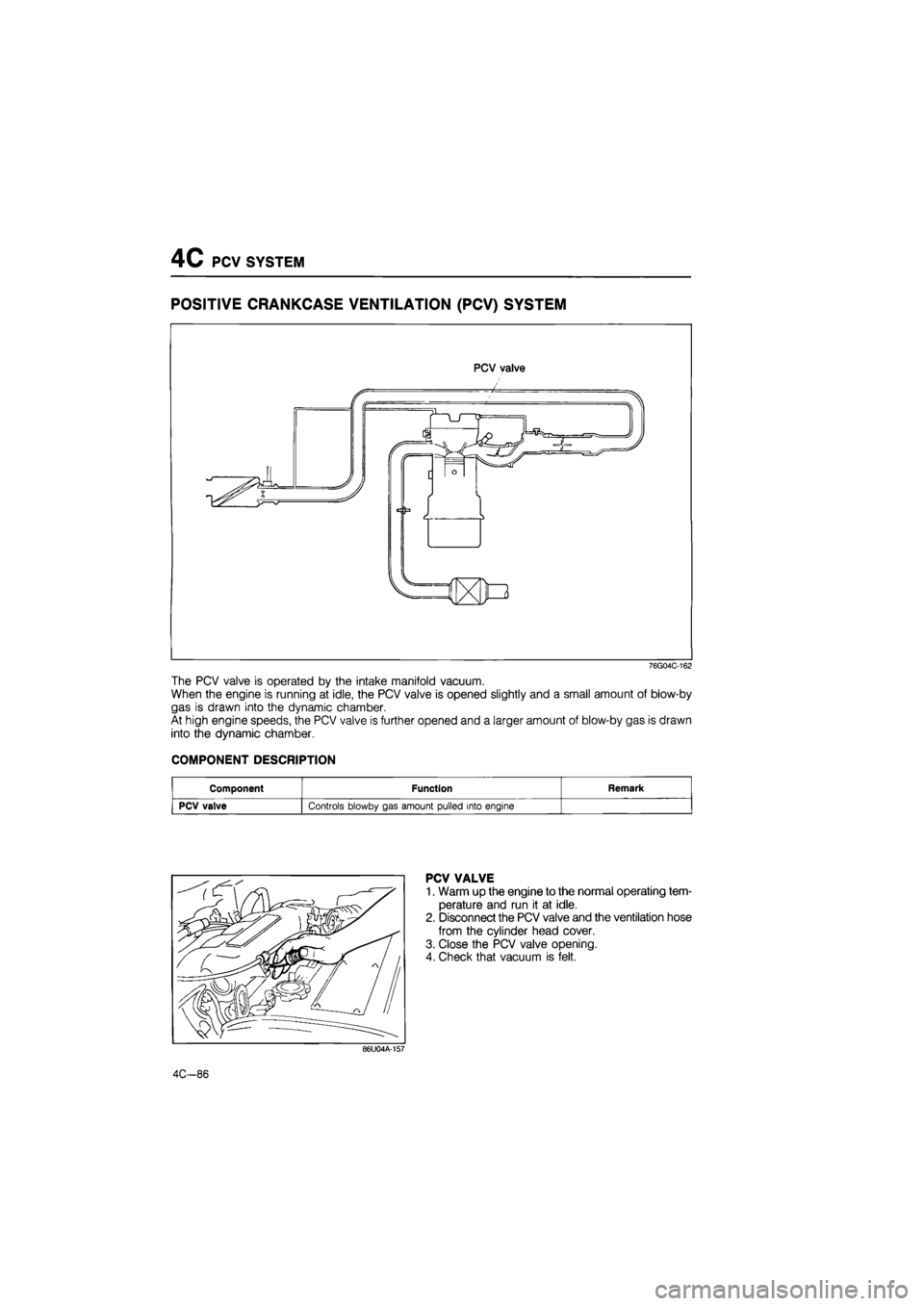
POSITIVE CRANKCASE VENTILATION
(PCV)
SYSTEM
PCV valve
76G04C-162
The PCV valve is operated by the intake manifold vacuum.
When the engine is running at idle, the PCV valve is opened slightly and a small amount of blow-by
gas is drawn into the dynamic chamber.
At high engine speeds, the PCV valve is further opened and a larger amount of blow-by gas is drawn
into the dynamic chamber.
COMPONENT DESCRIPTION
Component Function Remark
PCV valve Controls blowby gas amount pulled into engine
PCV VALVE
1. Warm up the engine to the normal operating tem-
perature and run it at idle.
2. Disconnect the PCV valve and the ventilation hose
from the cylinder head cover.
3. Close the PCV valve opening.
4. Check that vacuum is felt.
86U04A-157
4C-86