light MAZDA 626 1987 User Guide
[x] Cancel search | Manufacturer: MAZDA, Model Year: 1987, Model line: 626, Model: MAZDA 626 1987Pages: 1865, PDF Size: 94.35 MB
Page 111 of 1865

ASSEMBLY (CYLINDER HEAD) 1 A
Outer valve spring
®
®
Cylinder head r
Side ®>d)
76G01A-079
86U01X-145
86U01X-146
© @ ® ©
© ® © ®
Valve and Valve Spring
1. Install the lower spring seat.
2. Install the valve.
3. Install the valve springs and the upper spring seat.
Note
Install the outer valve spring with the closer
pitch toward the cylinder head.
4. Compress the valve spring with the SST; then in-
stall the valve keepers.
5. Tap the end of the valve stem lightly two or three
times with a plastic hammer to confirm that the
keepers are all fully seated.
Cylinder Head
1. Thoroughly remove all dirt, oil, or other material
from the top of the cylinder block.
2. Place the new cylinder head gasket in position.
3. Install the cylinder head.
4. Apply engine oil to the bolt threads and seat faces.
5. Tighten the cylinder head bolts in two or three steps
in the order shown in the figure.
Tightening torque:
80—86
N
m (8.2—8.8 m-kg, 59—64 ft-lb)
86U01X-147
1A—79
Page 130 of 1865
1A INSTALLATION
76G01A-147
86U01X-199
86U01X-200
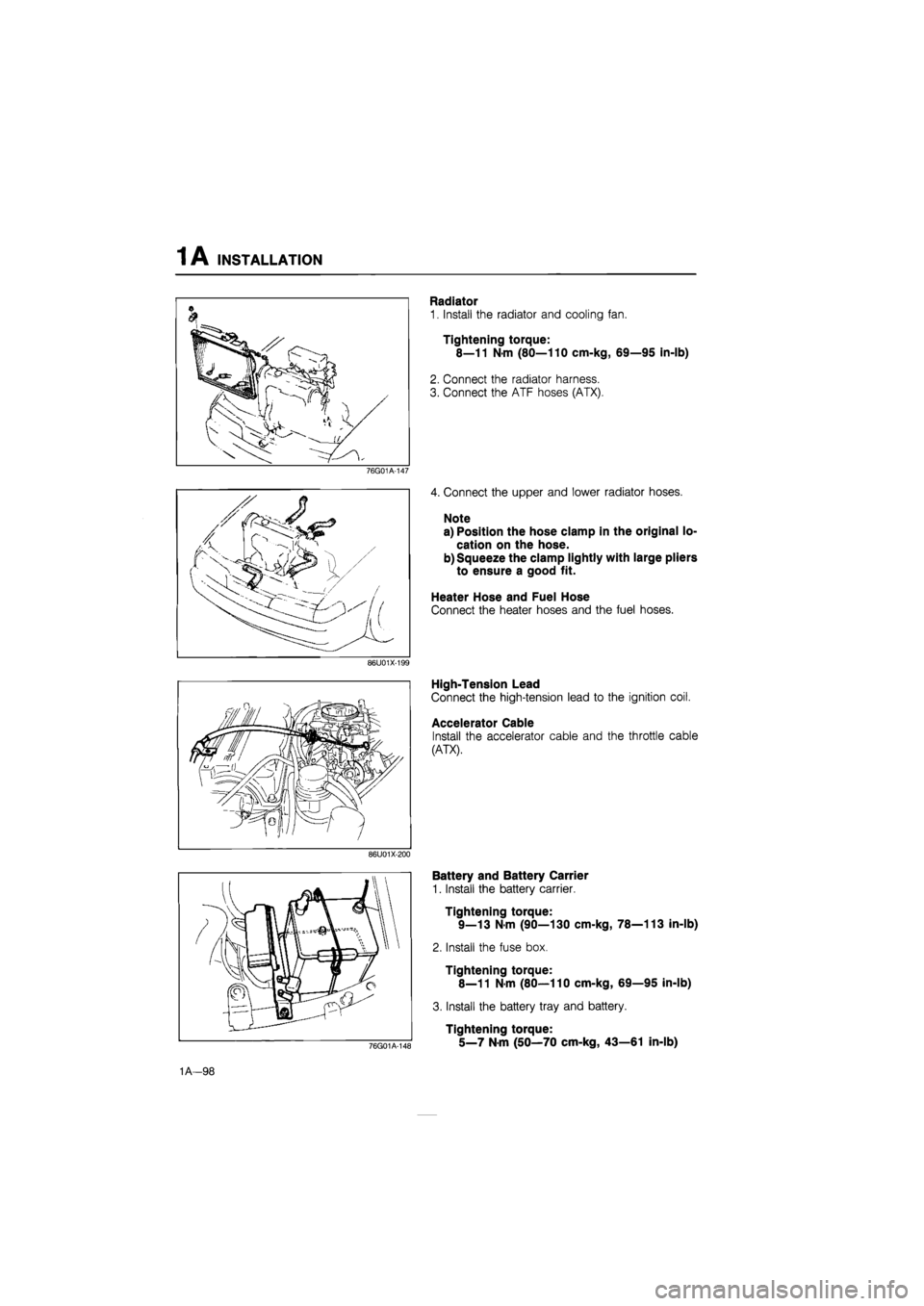
Radiator
1. Install the radiator and cooling fan.
Tightening torque:
8—11 N-m (80—110 cm-kg, 69—95 in-lb)
2. Connect the radiator harness.
3. Connect the ATF hoses (ATX).
4. Connect the upper and lower radiator hoses.
Note
a) Position the hose clamp in the original lo-
cation on the hose.
b) Squeeze the clamp lightly with large pliers
to ensure a good fit.
Heater Hose and Fuel Hose
Connect the heater hoses and the fuel hoses.
High-Tension Lead
Connect the high-tension lead to the ignition coil.
Accelerator Cable
Install the accelerator cable and the throttle cable
(ATX).
76G01A-148
Battery and Battery Carrier
1. Install the battery carrier.
Tightening torque:
9—13 N-m (90—130 cm-kg, 78—113 in-lb)
2. Install the fuse box.
Tightening torque:
8—11 N-m (80—110 cm-kg, 69—95 in-lb)
3. Install the battery tray and battery.
Tightening torque:
5_7 Nm (50—70 cm-kg, 43—61 in-lb)
1A—98
Page 139 of 1865
TUNE-UP PROCEDURE 1 B
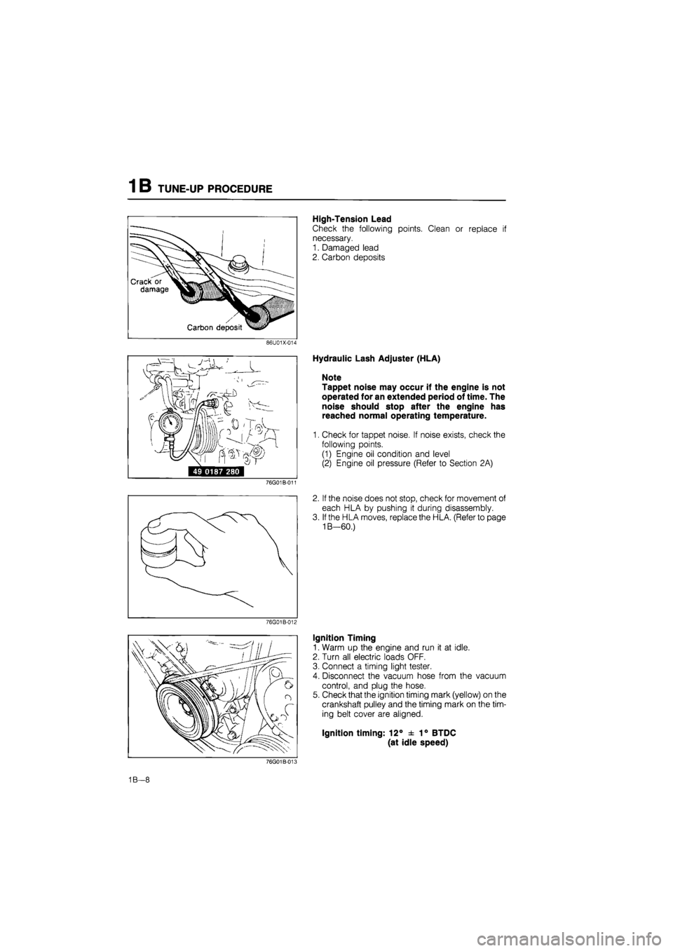
High-Tension Lead
Check the following points. Clean or replace if
necessary.
1. Damaged lead
2. Carbon deposits
86U01X-014
i^rrr ' /
49 0187 280
76G01B-011
76G01B-012
Hydraulic Lash Adjuster (HLA)
Note
Tappet noise may occur if the engine is not
operated for an extended period of time. The
noise should stop after the engine has
reached normal operating temperature.
1. Check for tappet noise. If noise exists, check the
following points.
(1) Engine oil condition and level
(2) Engine oil pressure (Refer to Section 2A)
2. If the noise does not stop, check for movement of
each HLA by pushing it during disassembly.
3. If the HLA moves, replace the HLA. (Refer to page
1B—60.)
Ignition Timing
1. Warm up the engine and run it at idle.
2. Turn all electric loads OFF.
3. Connect a timing light tester.
4. Disconnect the vacuum hose from the vacuum
control, and plug the hose.
5. Check that the ignition timing mark (yellow) on the
crankshaft pulley and the timing mark on the tim-
ing belt cover are aligned.
Ignition timing: 12° ± 1° BTDC
(at idle speed)
76G01B-008
1B—8
Page 150 of 1865

1 B ON-VEHICLE MAINTENANCE (CYLINDER HEAD)
Installation
Install in the reverse order of removal referring to the installation note.
Note a) Position the hose clamp in the original location on the hose.
b) Squeeze the clamp lightly with large pliers to ensure a good fit.
Torque Specifications
8—12 N-m (80—120 cm-kg, 69—104
4—6 N-m (40—60 cm-kg, 35—52 in
15—23 N-m (1.5—2.3 m-kg, 11—17 ft-lb)
7—10 N-m (70—100 cm-kg, 61—87 In-lb)
—11 N-m (80—110 cm-kg, 69—95 In-lb)
37—52 N-m (3.8—5.3 m-kg. 27—38 ft-lb)
80—86 N-m (8.2—8.8 m-kj, 59—64 ft-lb)
~t/—- -19—30 N-m (1.9—3.1 m-kg, g^ 14-22 ft-lb)
\34—44
N-m (3.5—4.5 m-kg, ' 25—33 ft-lb)
19-30 N-m (1.9—3.1 m-kg, 14—22 ft-lb)
19—30 N-m (1.9—3.1 m-kg, 14—22 ft-lb)
37—52 N-m (3.8—5.3 m-kg, 27—38 ft-lb)
76G01A-112
1B—19
Page 191 of 1865
1 B ASSEMBLY (CYLINDER HEAD)
Valve spring
®>®
Cylinder head side
76G01B-084
86U01X-145
76G01B-085
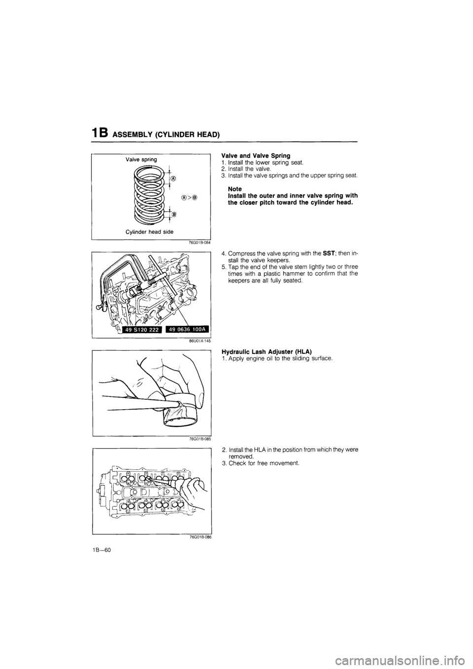
Valve and Valve Spring
1. Install the lower spring seat.
2. Install the valve.
3. Install the valve springs and the upper spring seat.
Note
Install the outer and inner valve spring with
the closer pitch toward the cylinder head.
4. Compress the valve spring with the SST; then in-
stall the valve keepers.
5. Tap the end of the valve stem lightly two or three
times with a plastic hammer to confirm that the
keepers are all fully seated.
Hydraulic Lash Adjuster (HLA)
1. Apply engine oil to the sliding surface.
2. Install the HLA in the position from which they were
removed.
3. Check for free movement.
76G01B-086
1B—60
Page 211 of 1865
1B INSTALLATION
76G01B-113
76G01B-114
76G01B-115
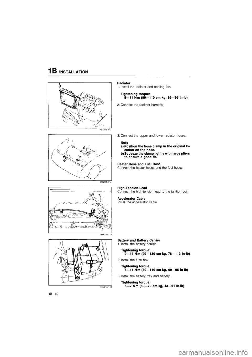
Radiator
1. Install the radiator and cooling fan.
Tightening torque:
8—11 N-m (80—110 cm-kg, 69—95 in-lb)
2. Connect the radiator harness.
3. Connect the upper and lower radiator hoses.
Note
a) Position the hose clamp in the original lo-
cation on the hose.
b) Squeeze the clamp lightly with large pliers
to ensure a good fit.
Heater Hose and Fuel Hose
Connect the heater hoses and the fuel hoses.
High-Tension Lead
Connect the high-tension lead to the ignition coil.
Accelerator Cable
Install the accelerator cable.
76G01A-148
Battery and Battery Carrier
1. Install the battery carrier.
Tightening torque:
9—13 N-m (90—130 cm-kg, 78—113 in-lb)
2. Install the fuse box.
Tightening torque:
8—11
N
m (80—110 cm-kg, 69—95 in-lb)
3. Install the battery tray and battery.
Tightening torque:
5_7
N m
(50—70 cm-kg, 43—61 in-lb)
1B—80
Page 220 of 1865

1C TUNE-UP PROCEDURE
Comprex supercharger
Deflection mm (in)
New 4 0-6.0 (0.16—0.23)
Used 8.0-10 0 (0 31-0.39)
If necessary, loosen the idler lock nut and adjust
the belt deflection by turning the adjust bolt.
Tightening torque:
16—23 Nm (1.6—2.3 m-kg, 12—17 ft-lb)
76G01C-011
o
INJECTION TIMING
1. Disconnect the negative battery cable.
2. Release the CSD using the screw driver.
3. Remove the cover on the clutch housing.
4. Turn the flywheel and set the indicator at ATDC.
5. Disconnect the injection pipes from the injection
pump.
76G04D-008
6. Remove the hydraulic head plug from the injec-
tion pump.
7. Mount the SST into the plug hole on the hydraulic
head so the tip of the dial gauge pointer touches
the plunger end of the pump and the dial gauge
indicates approx. 2.0 mm (0.08 in).
76G04D-009
8. Turn the crankshaft slowly counterclockwise to
30-50° BTDC.
9. Make sure the dial indicator pointer no longer
moves by slightly turning the crankshaft.
10. Set the dial gauge scale to Zero at the pointer.
76G04D-010
1C-8
Page 231 of 1865

ON-VEHICLE MAINTENANCE (CYLINDER HEAD) 1 C
Installation
Install in the reverse order of removal referring to the installation note.
Note a) Position the hose clamp in the original location on the hose.
b) Squeeze the clamp lightly with large pliers to ensure a good fit.
Torque Specifications
59—69 N m (6.0—7.0 m-kg, 43—51 ft-lb)
55—65 N-m (5.6—6.6 m-kg, 41—48 ft-lb)
7-10 N-m (70—100 cm-kg, 61-87 in-lb)
8—11 N-m (80—110 cm-kg, 69—95 in-lb)
8—11 N-m (80—110 cm-kg. 69—95 In-lb)
55—65 N-m i—6.6 m-kg, 48 ft-lb)
—11 N-m (80—110 cm-kg, 69—95 in-lb)
7—10 N-m (70—100 cm-kg, 61—87 in-lb)
8—11 N-m (80—110 cm-kg, 69—95 in-lb)
34—49 N-m (3.5—!
\, - 16—27 N-m (1.6—2.8 m-kg, N > 12—20 ft-lb)
19—26 N-m (1.9—2.6 m-kg, 14—19 ft-lb)
76G01C-242
1C—19
Page 235 of 1865
ON-VEHICLE MAINTENANCE (CYLINDER HEAD) 1 C
76G01C-049
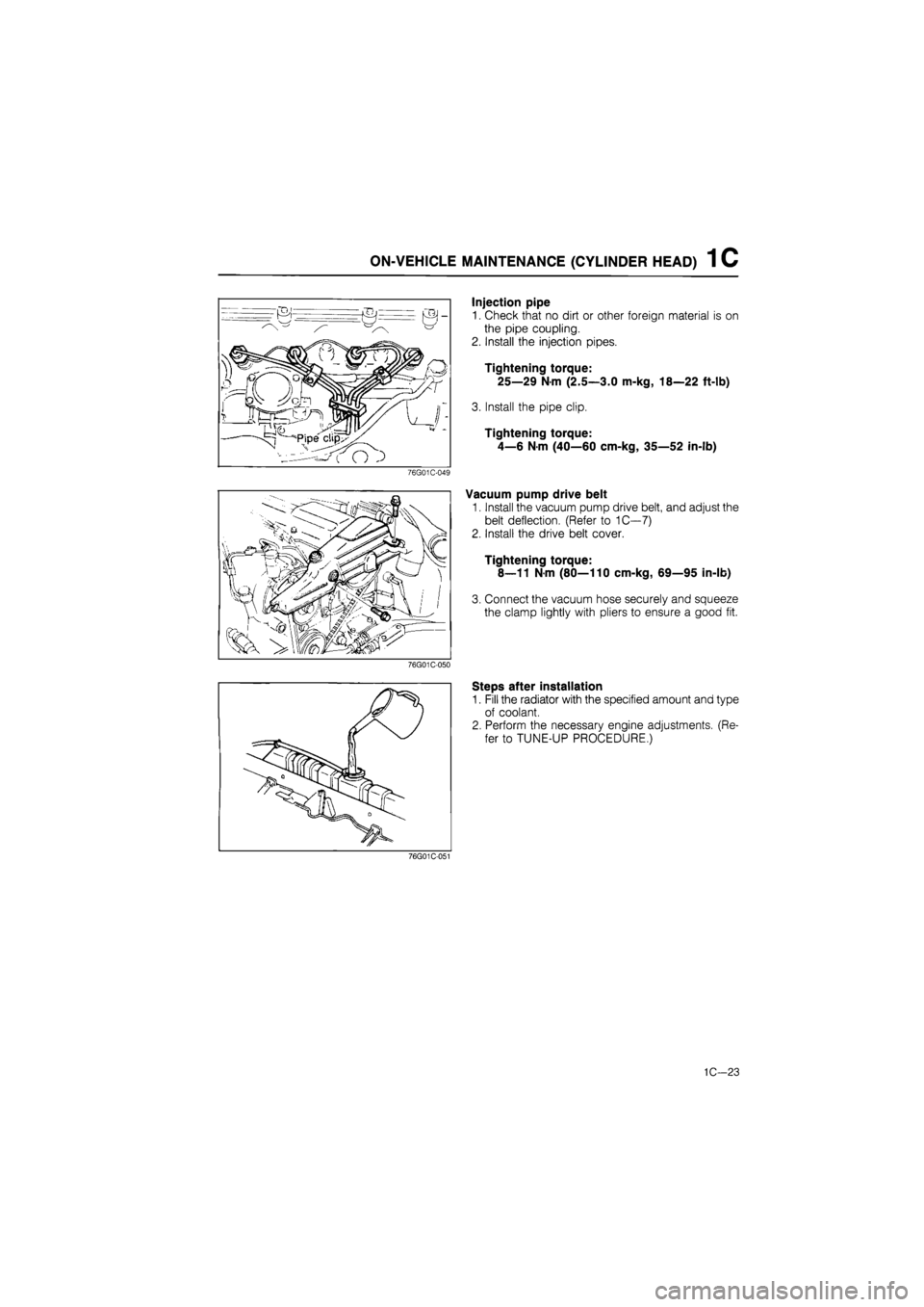
Injection pipe
1. Check that no dirt or other foreign material is on
the pipe coupling.
2. Install the injection pipes.
Tightening torque:
25—29 Nm (2.5—3.0 m-kg, 18—22 ft-lb)
3. Install the pipe clip.
Tightening torque:
4—6 N-m (40—60 cm-kg, 35—52 in-lb)
Vacuum pump drive belt
1. Install the vacuum pump drive belt, and adjust the
belt deflection. (Refer to 1C—7)
2. Install the drive belt cover.
Tightening torque:
8—11 Nm (80—110 cm-kg, 69—95 in-lb)
3. Connect the vacuum hose securely and squeeze
the clamp lightly with pliers to ensure a good fit.
76G01C-050
Steps after installation
1. Fill the radiator with the specified amount and type
of coolant.
2. Perform the necessary engine adjustments. (Re-
fer to TUNE-UP PROCEDURE.)
76G01C-051
1C—23
Page 286 of 1865

1 C ASSEMBLY (CYLINDER
BLOCK)
76G01C-170
Adjusting
disc
Tappet -
Apply engine oil
4BG01B-150
4BG01B-182
Apply engine oil
1.
Cylinder head bolt
below head length
Valve and Valve Spring
1. Install the lower spring seat.
2. Apply molybdenum disulphide grease to the valve
stem.
3. Install the valve.
4. Install the valve springs and the upper spring seat.
5. Compress the valve spring with the SST; then in-
stall the valve keepers.
6. Tap the end of the valve stem lightly two or three
times with a plastic hammer to confirm that the
keepers are all fully seated.
Tappet and Adjusting Disc
1. Apply engine oil to the tappets.
2. Install the tappets in the hole.
3. Install the adjusting discs.
Cylinder Head
1. Thoroughly remove all dirt and grease from the top
of the cylinder block with a rag.
2. Place the new cylinder head gasket in position.
3. Remove any dirt or grease from the bottom sur-
face of the cylinder head.
4. Place the cylinder head in position.
5. Measure the length of the cylinder head bolt be-
low the head. If the length exceeds the maximum,
replace the bolt.
Length: 113.2—113.8 mm (4.457—4.480 in)
Maximum: 114.5 mm (4.508 in)
76G01C-171
1C-74