light MAZDA 626 1987 Repair Manual
[x] Cancel search | Manufacturer: MAZDA, Model Year: 1987, Model line: 626, Model: MAZDA 626 1987Pages: 1865, PDF Size: 94.35 MB
Page 574 of 1865
TROUBLESHOOTING WITH SST 4C
49 H018 9A1
negative battery cable
^ll
Test connector: (Green, 1 pin)
86U04A-015
Ignition switch:
ON
for six
seconds
76G04C-014
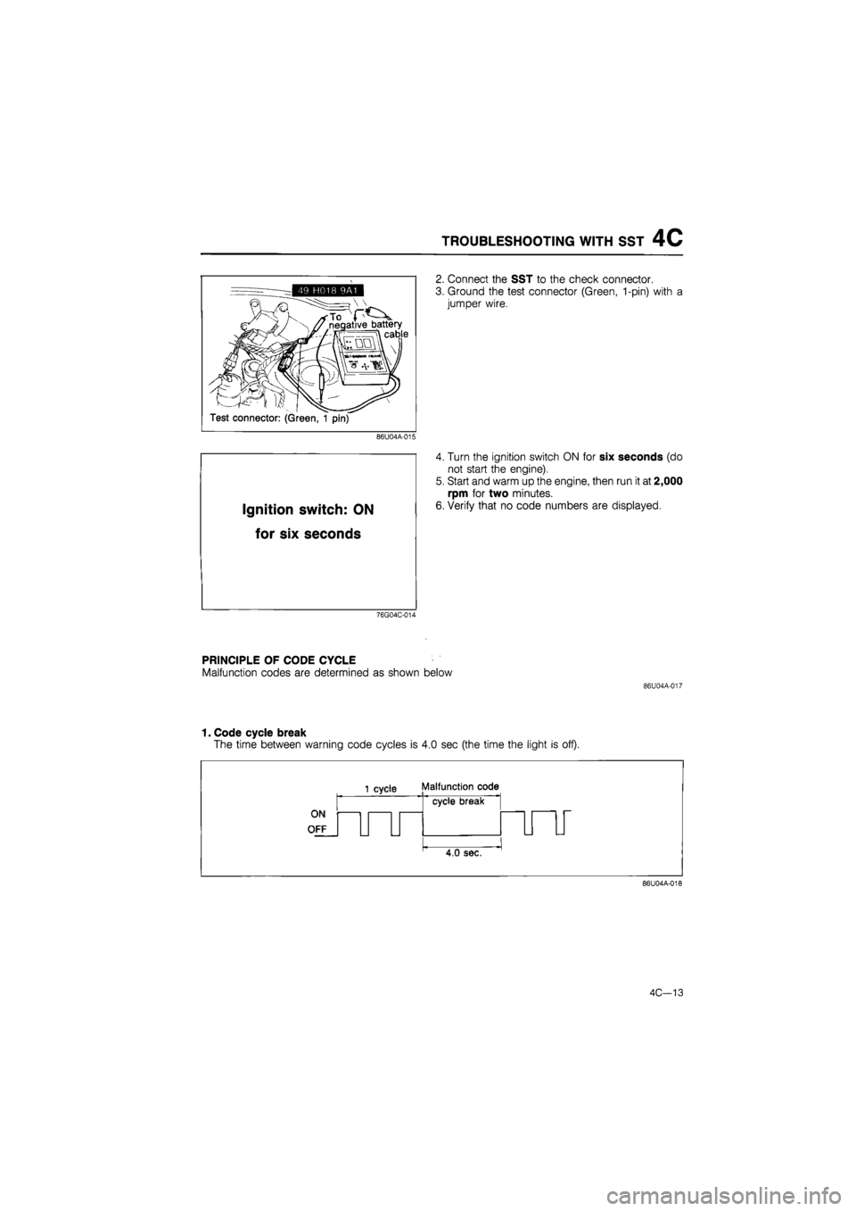
2. Connect the SST to the check connector.
3. Ground the test connector (Green, 1-pin) with a
jumper wire.
4. Turn the ignition switch ON for six seconds (do
not start the engine).
5. Start and warm up the engine, then run it at 2,000
rpm for two minutes.
6. Verify that no code numbers are displayed.
PRINCIPLE OF CODE CYCLE
Malfunction codes are determined as shown below
86U04A-017
1. Code cycle break
The time between warning code cycles is 4.0 sec (the time the light is off).
ON
OFF
1 cycle Malfunction code
cycle break
4.0 sec.
86U04A-018
4C—13
Page 575 of 1865

4C TROUBLESHOOTING WITH SST
2. Second digit of malfunction code (ones position)
The digit in the ones position of the malfunction code represents the number of times the buzzer
is on 0.4 sec during one cycle.
ON
OFF
1 cycle Malfunction code
1 2 3 cycle break
Malfunction
code: 03
n^j
0.4 0.4 sdc. sec.
4.0 sec.
76G04C-015
3. First digit of malfunction code (tens position)
The digit in the tens position of the malfunction code represents the number of times the buzzer
is on 1.2 sec during one cycle.
It should also be noted that the light goes off for 1.6 sec. between the long and short pulses of
the buzzer.
1 cycle Malfunction code
1 2
~U 0.4
1.2 sec. sec h
1 2|
flfl
First digit
1.6 sec.
cycle break
Malfunction
code: 22
nr
4.0 sec.
Second
digit
76G04C-016
CODE NUMBER
Malfunction display
Sensor or
subsystem Self-diagnosis Fail-safe Malfunction
code no.
Malfunction code output signal pattern
Sensor or
subsystem Self-diagnosis Fail-safe
02 o°nfJLJJL
Ne signal No Ne signal from crank angle sensor during craking
03 oppJUllUl
G signal No G signal Cancels sequencial
injection
05
Knock sensor (only
leaded fuel)
Open or short circuit • Retards ignition timing 4°
76G04C-017
4C—14
Page 586 of 1865

SWITCH MONITOR FUNCTION 4C
SWITCH MONITOR FUNCTION
Individual switches can be monitored by the SST (Self-Diagnosis checker 49 G018 9A0 or Digital
code checker 49 9200 180).
Note
The test connector must be grounded and the ignition switch ON (engine stopped).
Engine control unit
76G04C-035
Switch Self-Diagnosis Checker (Monitor lamp) Remark Switch Light ON Light OFF Remark
Clutch switch Pedal released Pedal depressed In gear
Neutral switch In gear Neutral Clutch pedal released
Idle switch Pedal depressed Pedal released —
Headlight switch ON OFF —
Rear defroster switch ON OFF —
Blower switch ON OFF Blower motor position: "3" or "4"
Water thermo switch (Elec-trical fan) Terminal disconnected Terminal connected While fan not operating
4C—25
Page 588 of 1865

SWITCH MONITOR FUNCTION 4C
Idle switch
76G04C-039
Blower switch
76G04C-040
Headlight switch
76G04C-041
Rear defroster switch
76G04C-042
4C—27
Page 608 of 1865

ISC SYSTEM 4C
76G04C-081
76G04C-082
Cooling fan switch
Rear defroster switch
Head light switch
Blower motor switch
ISC "valve
76G04C-083
(ISC valve)
6. Connect the ISC valve connector.
Note
a) Make sure that the initial idle speed is set
to specification.
b) All accessory must be OFF.
7. Again disconnect the ISC valve connector (engine
at normal operating temperature).
8. Check that the engine speed decreases.
9. Reconnect the ISC valve connector.
10 Remove the jumper wire from the test connector
and make sure that the idle speed is within specifi-
cations.
(Load Test)
11. Apply power steering, electrical, and air conditioner
loads and check that the idle speed is controlled
to within specifications.
Load Idle speed
P/S 750 ± 50
E/L 800 ± 50
A/C 800 ± 50
E/L and A/C 800 ± 50
BAC Valve
Air valve
1. Remove the BAC valve from the throttle body.
2. Blow air through the valve from port A and check
that air comes out of port B when the BAC valve
is cold..
3. If not correct, replace the BAC valve.
Note
Refer to "Installation" on this page for the
BAC valve installation.
86U04A-063
4C—47
Page 647 of 1865
4C PCV SYSTEM
POSITIVE CRANKCASE VENTILATION
(PCV)
SYSTEM
PCV valve
76G04C-162
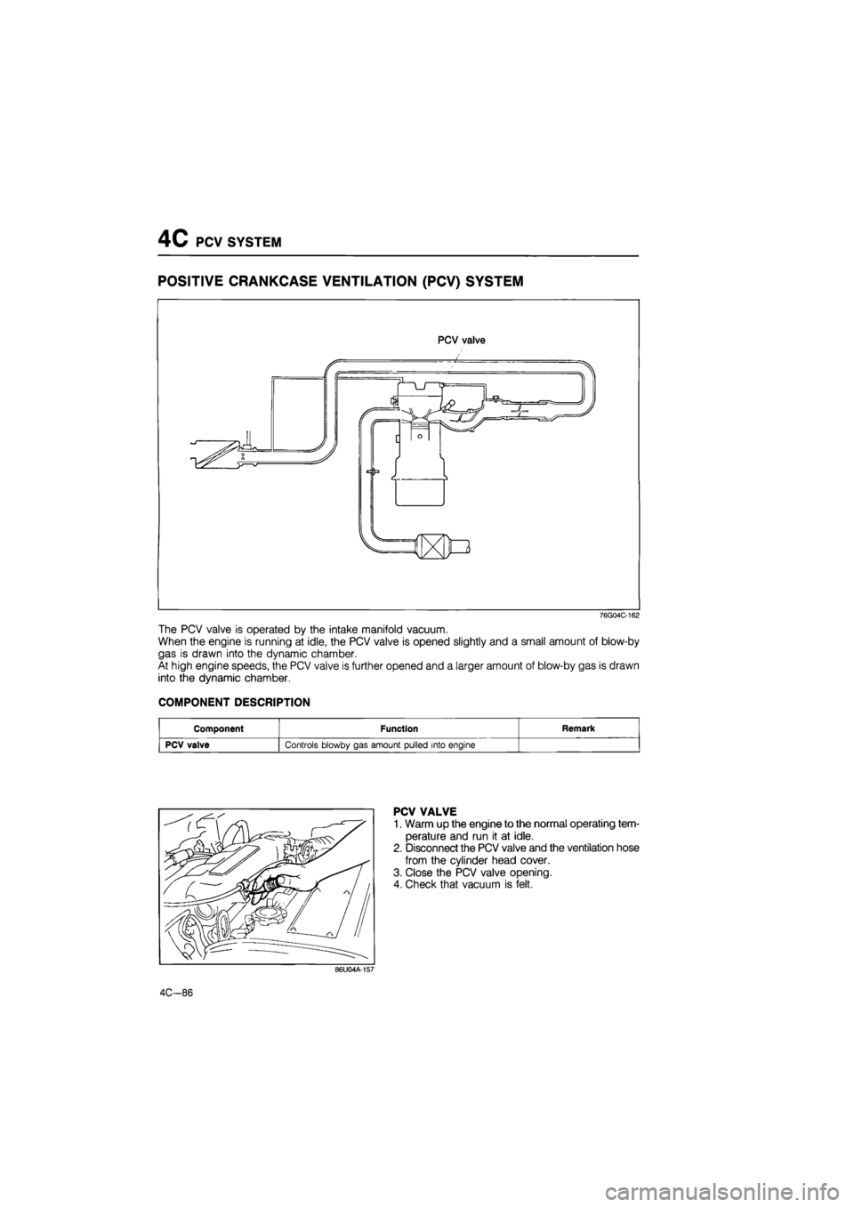
The PCV valve is operated by the intake manifold vacuum.
When the engine is running at idle, the PCV valve is opened slightly and a small amount of blow-by
gas is drawn into the dynamic chamber.
At high engine speeds, the PCV valve is further opened and a larger amount of blow-by gas is drawn
into the dynamic chamber.
COMPONENT DESCRIPTION
Component Function Remark
PCV valve Controls blowby gas amount pulled into engine
PCV VALVE
1. Warm up the engine to the normal operating tem-
perature and run it at idle.
2. Disconnect the PCV valve and the ventilation hose
from the cylinder head cover.
3. Close the PCV valve opening.
4. Check that vacuum is felt.
86U04A-157
4C-86
Page 660 of 1865

CONTROL SYSTEM 4C
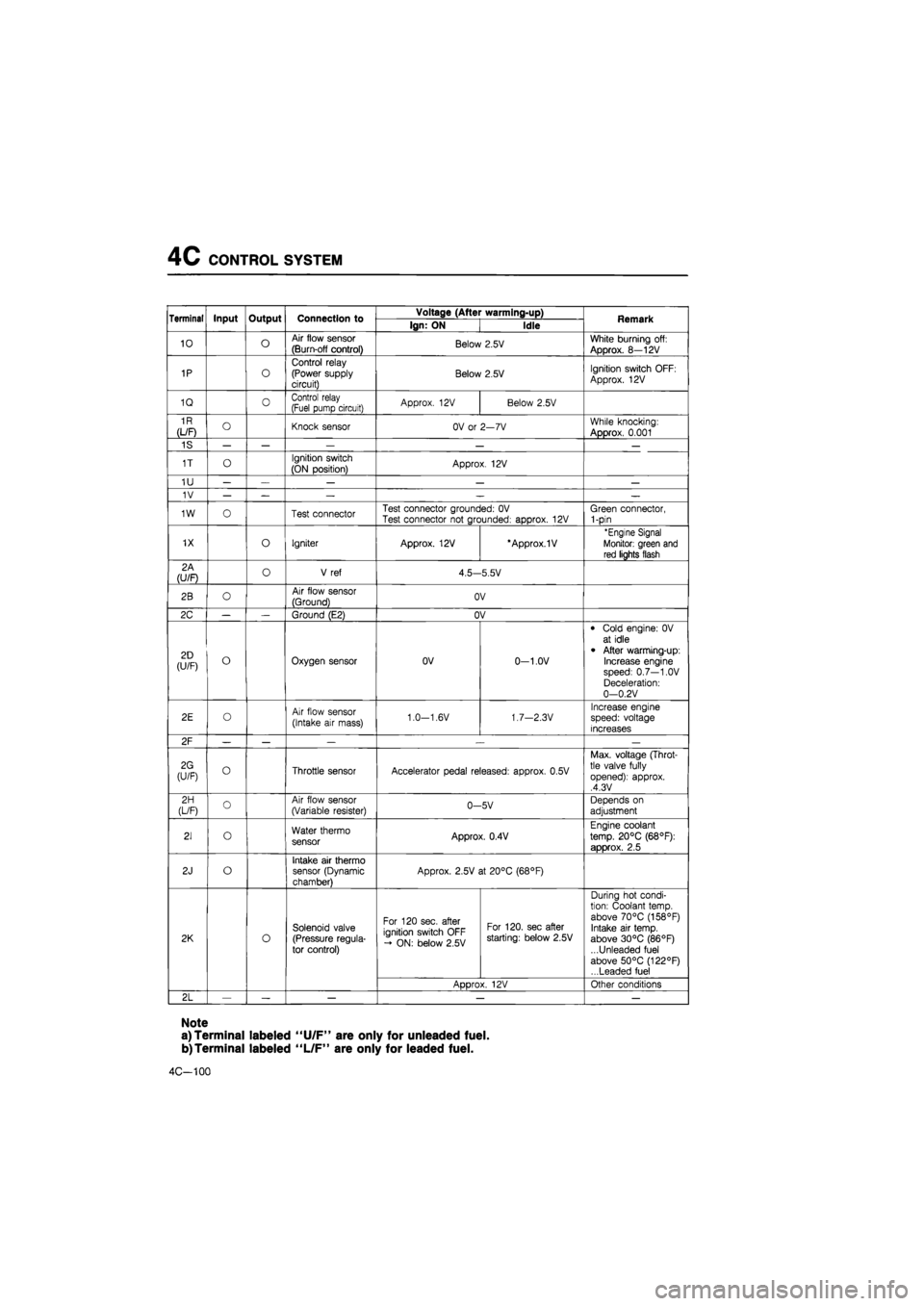
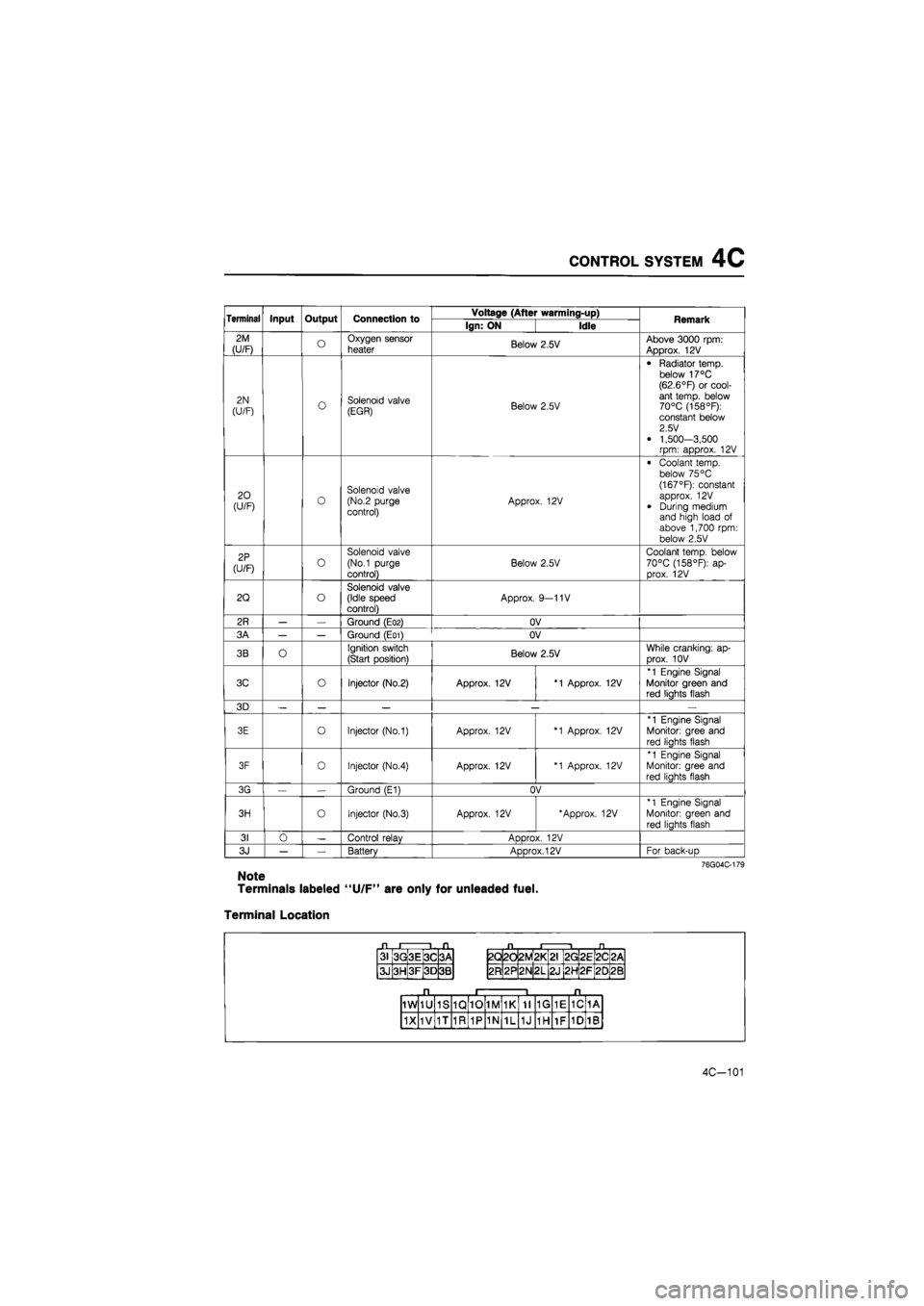
Terminal Voltage
If the input and output devices wiring are normal, but the engine control unit terminal voltage is incor-
rect, replace the engine control unit.
Terminal Input Output Connection to Voltage (After warming-up) Remark Terminal Input Output Connection to Ign: ON Idle Remark
1A — — — — — —
1B o Self-Diagnosis Checker (Code No.)
For 3sec. after ignition switch OFF ->• ON: below 2.5V (Buzzer sounds) After 3sec.: approx. 12V (Buzzer does not sound)
• Using Self-Diagnosis Check-er and test con-nector grounded • Buzzer sounds: below 2.5V • Buzzer does not sound: approx. 12V
1C o
Solenoid valve (Variable inertia control) Approx. 12V
Above 5200 rpm (Unleaded fuel) or 5400 rpm (Leaded fuel): Below 2.5V
1D o Self-Diagnosis Checker (Monitor lamp)
For 3sec.after igni-tion switch OFF -» ON:
approx. 5V (light il-luminates)
After 3sec.: approx. 12V (light does not illuminate)
(Test connector grounded) approx. 5V (Test connector not grounded) Monitor lamp ON: approx. 5V Monitor lamp OFF: approx. 12V
With Self-Diagnosis
Checker
1E O Idle switch Accelerator pedal released: OV
Accelerator pedal depressed: approx. 12V
1F o A/C relay A/C switch ON: below 2.5V
A/C switch OFF: approx. 12V Blower motor ON
1G O Neutral or clutch switch
In-gear condition Clutch pedal depressed: approx. 12V Clutch pedal released: OV
MTX (Neutral: con-stant approx. 12V)
1H
(U/F) o Water thermo
switch
Approx. 12V Radiator temp.: be-low 17°C (63°R 1H
(U/F) o Water thermo
switch OV Radiator temp.:
above 17°C (63°F)
11 o Electrical load control unit E/L switch ON: below 2.5V
E/L switch OFF: approx. 10—12V
Electrical load: Rear defroster switch
Headlight switch Blower motor switch (3rd & 4th position) Electrical fan switch
1J — — — — —
1K o P/S pressure
switch
Constant approx.
12V
P/S ON: below 2.5V P/S OFF: approx. 12V
1L o A/C switch A/C switch ON: below 2.5V A/C switch OFF: aDDrox. 12V Blower motor: ON
1M o Distributor
(Ne signal) OV or 5V Approx. 2.0V
1N o Distributor (G signal) OV or 5V Approx. 1.2V
Note
Terminals labeled "U/F" are only for unleaded fuel.
4C-99
Page 661 of 1865
4C CONTROL SYSTEM
Terminal Input Output Connection to Voltage (After warming-up) Remark Terminal Input Output Connection to Ign: ON Idle Remark
10 o Air flow sensor
(Burn-off control) Below 2.5V White burning off:
Approx. 8—12V
1P o
Control relay (Power supply circuit) Below 2.5V Ignition switch OFF:
Approx. 12V
1Q 0 Control relay (Fuel pump circuit) Approx. 12V Below 2.5V
1R
(L/F) O Knock sensor OV or 2—7V While knocking:
Approx. 0.001
1S — — — — —
1T o Ignition switch
(ON position) Approx. 12V
1U — — — — —
1V — — — — —
1W o Test connector Test connector grounded: OV Test connector not grounded: approx. 12V Green connector, 1-pin
1X o Igniter Approx. 12V *Approx.1V 'Engine Signal
Monitor: green and
red lights flash
2A (U/F) o V ref 4.5—5.5V
2B o Air flow sensor
(Ground) OV
2C — — Ground (E2) OV
2D (U/F) o Oxygen sensor OV 0-1.0V
• Cold engine: 0V at idle
• After warming-up: Increase engine speed: 0.7—1.0V Deceleration: 0—0.2V
2E o Air flow sensor
(Intake air mass) 1.0—1.6V 1.7—2.3V Increase engine speed: voltage increases
2F — — — .— —
2G (U/F) o Throttle sensor Accelerator pedal released: approx. 0.5V
Max. voltage (Throt-tle valve fully opened): approx. ,4.3V
2H (L/F) o Air flow sensor (Variable resister) 0-5V Depends on
adjustment
21 o Water thermo sensor Approx. 0.4V
Engine coolant
temp. 20°C (68°F):
approx. 2.5
2J o Intake air thermo sensor (Dynamic chamber)
Approx. 2.5V at 20°C (68°F)
2K o
Solenoid valve (Pressure regula-tor control)
For 120 sec. after ignition switch OFF - ON: below 2.5V
For 120. sec after starting: below 2.5V
During hot condi-tion: Coolant temp, above 70°C (158°F) Intake air temp, above 30°C (86°F) ...Unleaded fuel above 50°C (122°F) ...Leaded fuel
2K o
Solenoid valve (Pressure regula-tor control)
ADDrox. 12V Other conditions
2L — — — — —
Note
a) Terminal labeled "U/F" are only for unleaded fuel.
b)Terminal labeled "L/F" are only for leaded fuel.
4C-100
Page 662 of 1865
CONTROL SYSTEM 4C
Terminal Input Output Connection to Voltage (After warming-up) Remark Terminal Input Output Connection to Ign: ON Idle Remark
2M
(U/F) o Oxygen sensor
heater Below 2.5V Above 3000 rpm: Approx. 12V
2N
(U/F) o Solenoid valve (EGR) Below 2.5V
• Radiator temp, below 17°C (62.6°F) or cool-ant temp, below 70°C (158°F): constant below 2.5 V
• 1,500-3,500 rpm: approx. 12V
20 (U/F) 0 Solenoid valve (No.2 purge control) Approx. 12V
• Coolant temp, below 75 °C (167°F): constant approx. 12V
• During medium and high load of above 1,700 rpm: below 2.5V
2P
(U/F) o
Solenoid valve
(No.1 purge
control)
Below 2.5V
Coolant temp, below 70°C (158°F): ap-prox. 12V
2Q o Solenoid valve (Idle speed control) Approx. 9—11V
2R — — Ground (E02) OV
3A — — Ground (E01) OV
3B O Ignition switch
(Start position) Below 2.5V While cranking: ap-
Drox. 10V
3C o Injector (No.2) Approx. 12V *1 Approx. 12V
*1 Engine Signal Monitor green and red liahts flash
3D — — — — —
3E o Injector (No.1) Approx. 12V *1 Approx. 12V
*1 Engine Signal
Monitor: gree and
red liahts flash
3F 0 Injector (No.4) Approx. 12V *1 Approx. 12V
*1 Engine Signal Monitor: gree and red liahts flash
3G — Ground (E1) OV
3H o Injector (No.3) Approx. 12V 'Approx. 12V *1 Engine Signal
Monitor: green and
red lights flash
31 0 — Control relav ADDrox. 12V
3J — — Battery Approx. 12V For back-uD
76G04C-179
Note
Terminals labeled "U/F" are only for unleaded fuel.
Terminal Location
31 3G 3E 3C 3A
3J 3H 3F 3D 3B
2Q 2d 2M *
L
2G 2E 2C <
CM
2R 2P 2N 2L 2J 2H 2F 20 2B
1W 1U 1S 1Q 10 1M 1K 11 1G 1E 1C 1A
1X 1V 1T 1R 1P 1N 1L 1J 1H 1F 1D 1B
4C-101
Page 663 of 1865
4C CONTROL SYSTEM
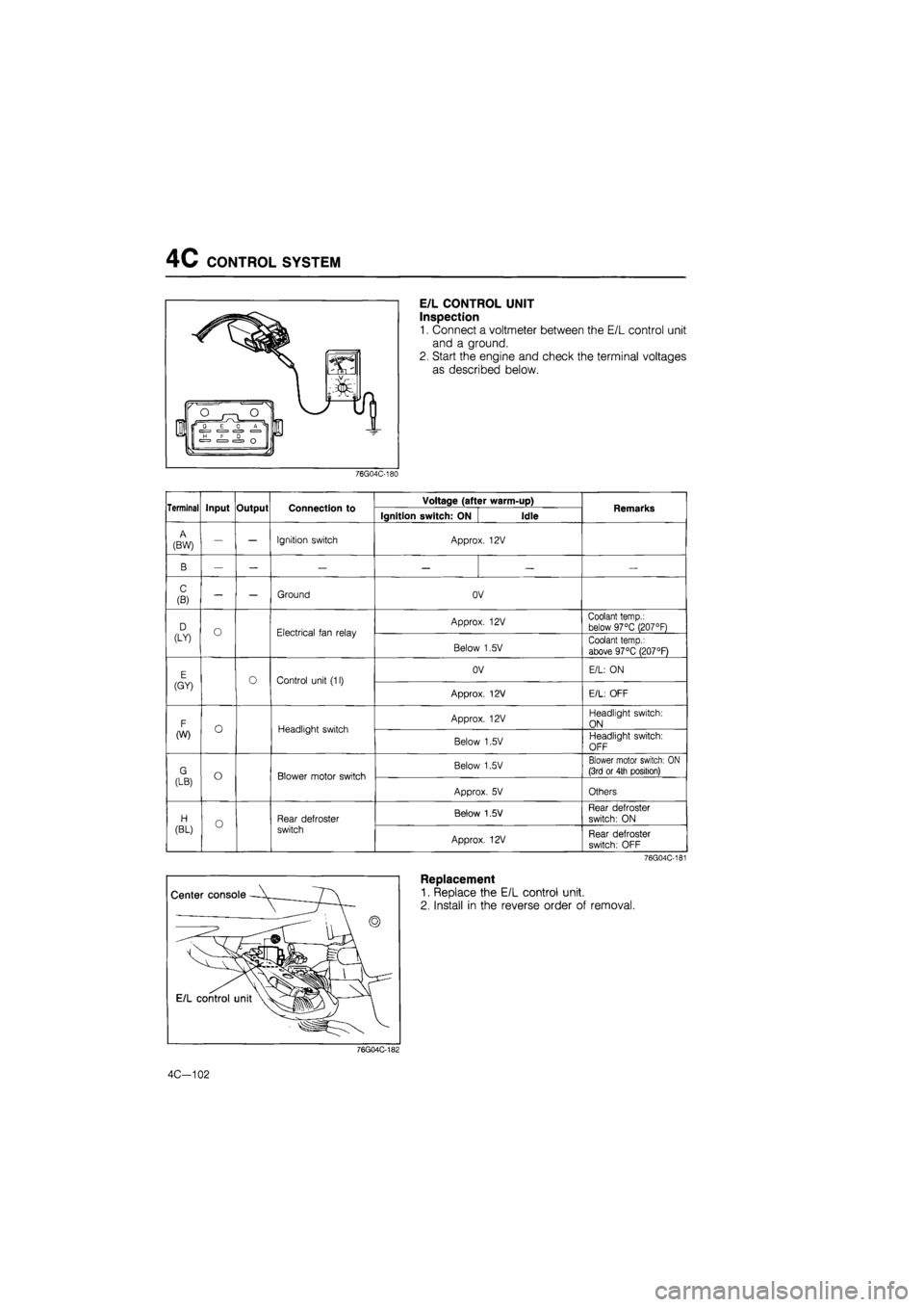
E/L CONTROL UNIT
Inspection
1. Connect a voltmeter between the E/L control unit
and a ground.
2. Start the engine and check the terminal voltages
as described below.
76G04C-180
Terminal Input Output Connection to Voltage (after warm-up) Remarks Terminal Input Output Connection to Ignition switch: ON Idle Remarks
A
(BW) — — Ignition switch Approx. 12V
B — — — — — —
C
(B) — — Ground OV
D (LY) O Electrical fan relay Approx. 12V Coolant temp.: below 97°C (207°F) D (LY) O Electrical fan relay
Below 1,5V Coolant temp.:
above 97°C (207°F)
E (GY) Control unit (11) OV E/L: ON E (GY) Control unit (11)
Approx. 12V E/L: OFF
F (W) O Headlight switch Approx. 12V Headlight switch:
ON F (W) O Headlight switch
Below 1,5V Headlight switch:
OFF
G (LB) o Blower motor switch Below 1.5V Blower motor switch: ON (3rd or 4th position) G (LB) o Blower motor switch
Approx. 5V Others
H
(BL) o Rear defroster
switch
Below 1.5 V Rear defroster
switch: ON H
(BL) o Rear defroster
switch Approx. 12V Rear defroster switch: OFF
76G04C-181
Replacement
1. Replace the E/L control unit.
2. Install in the reverse order of removal.
76G04C-182
4C—102