turn signal MAZDA 626 1987 User Guide
[x] Cancel search | Manufacturer: MAZDA, Model Year: 1987, Model line: 626, Model: MAZDA 626 1987Pages: 1865, PDF Size: 94.35 MB
Page 670 of 1865

CONTROL SYSTEM 4C
76G04C-203
76G04C-204
76G04C-205
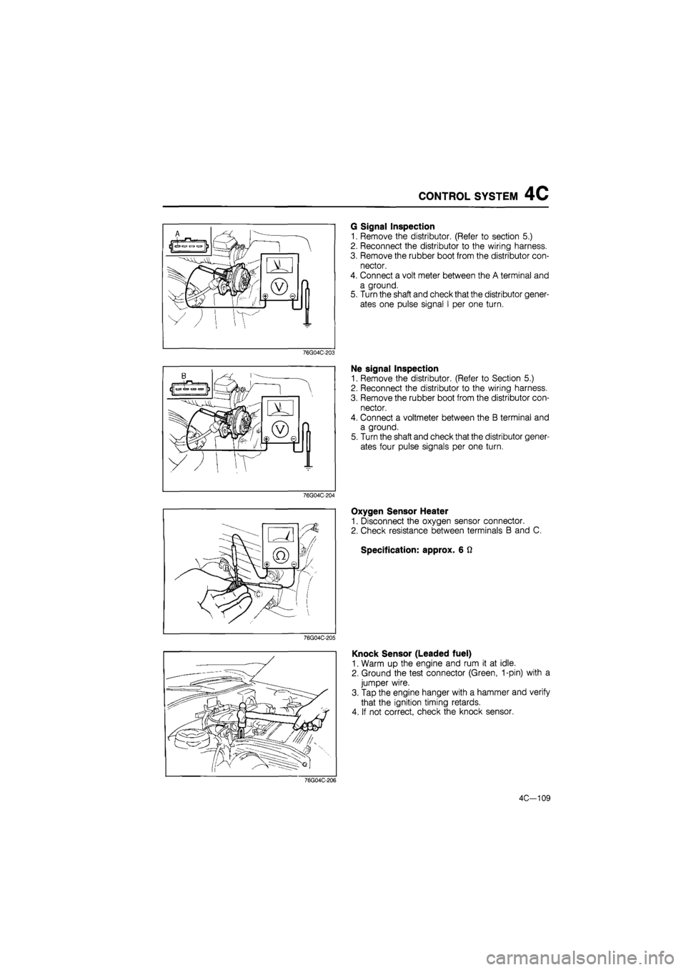
G Signal Inspection
1. Remove the distributor. (Refer to section 5.)
2. Reconnect the distributor to the wiring harness.
3. Remove the rubber boot from the distributor con-
nector.
4. Connect a volt meter between the A terminal and
a ground.
5. Turn the shaft and check that the distributor gener-
ates one pulse signal I per one turn.
Ne signal Inspection
1. Remove the distributor. (Refer to Section 5.)
2. Reconnect the distributor to the wiring harness.
3. Remove the rubber boot from the distributor con-
nector.
4. Connect a voltmeter between the B terminal and
a ground.
5. Turn the shaft and check that the distributor gener-
ates four pulse signals per one turn.
Oxygen Sensor Heater
1. Disconnect the oxygen sensor connector.
2. Check resistance between terminals B and C.
Specification: approx. 6 Q
Knock Sensor (Leaded fuel)
1. Warm up the engine and rum it at idle.
2. Ground the test connector (Green, 1-pin) with a
jumper wire.
3. Tap the engine hanger with a hammer and verify
that the ignition timing retards.
4. If not correct, check the knock sensor.
76G04C-206
4C-109
Page 890 of 1865

7B TROUBLESHOOTING (G4A-EL)
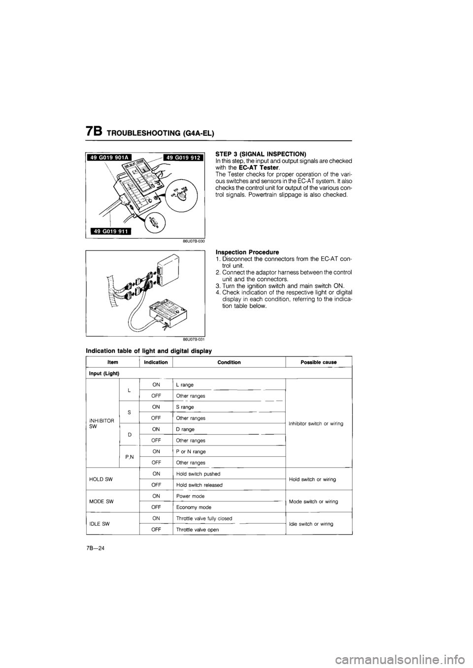
STEP 3 (SIGNAL INSPECTION)
In this step, the input and output signals are checked
with the EC-AT Tester.
The Tester checks for proper operation of the vari-
ous switches and sensors in the EC-AT system. It also
checks the control unit for output of the various con-
trol signals. Powertrain slippage is also checked.
Inspection Procedure
1. Disconnect the connectors from the EC-AT con-
trol unit.
2. Connect the adaptor harness between the control
unit and the connectors.
3. Turn the ignition switch and main switch ON.
4. Check indication of the respective light or digital
display in each condition, referring to the indica-
tion table below.
Indication table of light and digital display
Item Indication Condition Possible cause
Input (Light)
L ON L range L OFF Other ranges
S
ON S range
INHIBITOR
S OFF Other ranges Inhibitor switch or wiring SW
D ON D range
Inhibitor switch or wiring
D
OFF Other ranges
P,N
ON P or N range P,N OFF Other ranges
HOLD SW ON Hold switch pushed Hold switch or wiring HOLD SW
OFF Hold switch released
Hold switch or wiring
MODE SW ON Power mode Mode switch or wiring MODE SW
OFF Economy mode
Mode switch or wiring
IDLE SW ON Throttle valve fully closed Idle switch or wiring IDLE SW
OFF Throttle valve open
Idle switch or wiring
7B-24
Page 1579 of 1865

1 4 HEADLIGHT AND COMBINATION LIGHT
HEADLIGHT AND COMBINATION LIGHT
REMOVAL AND INSTALLATION
1. Disconnect the negative battery cable.
2. Remove in the sequence shown in the figure, referring to removal note for the specially marked parts.
3. Install in the reverse order of removal.
76G14X-005
1. Screw
2. Turn signal light assembly
3. Screw
4. Radiator grille
5. Bolts
6. Bolts
7. Headlight assembly
8. Screws
9. Light garnish
10. Headlight bulb
60 + 55W/55W
11. Parking light bulb 5W
12. Turn signal light bulb
21W
14—28
Page 1580 of 1865

HEADLIGHT AND COMBINATION LIGHT 1 4
76G14X-006
1. Screw 6. Bolts
2. Turn signal light assembly 7. Fastener
3. Screw 8. Screw
4. Radiator grille 9. Light garnish
5. Bolts 10. Headlight assembly
11. Headlight bulb
60 + 55/55W
12. Parking light bulb 5W
13. Turn signal light bulb
21W
14—29
Page 1581 of 1865

1 4 HEADLIGHT AND COMBINATION LIGHT
76G14X-007
86U14X-070
Removal Note
Turn signal light (Coupe/MX-6)
1. Remove the screws shown in the figure.
2. Disconnect the turn signal light connector.
3. Remove the turn signal light assembly.
Turn signal light (Sedan and Hatchback)
1. Remove the screws shown in the figure.
2. Disconnect the turn signal and parking light con-
nector.
3. Remove the turn signal and parking light assemble.
76G14X-008
14-30
Page 1583 of 1865

1 4 REAR COMBINATION LIGHTS
REAR COMBINATION LIGHTS
REMOVAL AND INSTALLATION
1. Disconnect the negative battery cable.
2. Remove in the sequence shown in the figure.
3. Install in the reverse order of removal.
76G14X-010
Hatchback
1. End trim
2. Nuts
3. Lens and body
4. Cover
5. Bulb: Turn signal light 21W
Brake and tail light 21W
Side marker light 5W
Sedan and Coupe/MX-6
1. End trim
2. Nuts
3. Lens and body
4. Cover
5. Bulb: Turn signal light 21W
Brake and tail light 21W
Side marker light 5W
14—32
Page 1667 of 1865

1 5 COMBINATION SWITCH
CONBINATION SWITCH
STRUCTURAL VIEW
Left hand drive
Alignment mark
Right hand drive
Alignment mark
76G15X-002
1. Light and turn signal switch lever
2. Windshield wiper and washer switch lever
3. Cruise control switch
4. Steering angle sensor
5. Hazard switch
6. Light switch connectors
7. Turn signal switch connector
8. Windshield wiper and washer switch con-
nector
9. Steering angle sensor connector
10. Turn signal and hazard switch connector
15—12
Page 1669 of 1865

1 5 COMBINATION SWITCH
76G15X-028
LHD SWH:AS=SWL
Turn signal switch
For LHD
~~ Terminal
Position
^
FU TL TR
Left
o— O
Right
Pi
Right
O
O:
indicates continuity
For RHD (with hazard switch)
Hazard
switch
OFF
ON
Turn
switch
Left
OFF
Right
OFF
FU
O O
o
TL TR
-O
TIG
O
O
o
HBA FB
-O
-O
-o
o—o
o
-O: indicates continuity
Windshield wiper and washer switch
Terminal
Position
Wiper
switch OFF OFF
ON
INT
(Low)
(High)
Washer switch
ON
AS
CD-
WIG SWL
-O
o-
o
o
SWH
o—o
-o
-o
-o
SW
o—o
O
O:
indicates continuity
RHD SWL AS SWH
SW WIG
76G15X-029
15—14
Page 1701 of 1865

1 5 TURN AND HAZARD LIGHT
TROUBLESHOOTING
Note
Check the TURN 15A fuse in the fuse box before troubleshooting.
Terminal Voltage
H (BG) 12V
OK
Check the voltage between each terminal
of
flasher unit connector and
a
body ground with each con-dition.
Terminal Condition Voltage
A(B) Any time OV
E (BR) Turn switch
is
Riaht 12V
F (GY) Turn switch
is
left 12V
H (Br) Anv time 12V
OK
Turn function does not operate.
Check the flasher unit. Refer
to
page 15—47
OK
Check the turn signal switch. Refer
to
page 15—14
OK
NG
NG
Check the voltage
at H
(BG) terminal
of
the combina-tion switch (Turn).
Replace the unit.
Replace the switch.
NG
Repair harness. (Fuse box
to
combination switch)
Repair harness.
NG
Terminal Wiring harness
A (B) Flasher unit
to
ground
E (BR) Flasher unit
to
combination switch
F (GY) Flasher unit
to
combination switch
H (Bri Fuse box
to
Flasher unit
Check the lights and wiring harness (Each bulb
to a
body ground)
NG
Replace the lights
or
repair the wiring harness.
OK
Repair harness. (Flasher unit
to
each bulb)
76G15X-045
Hazard function does not operate. (Turn func-tion is normal)
Check the hazard switch. Refer
to
page 15—19,
20
OK
NG
Replace the switch.
Check the voltage
at
each terminal
of
the hazard
switch connector.
Terminal Voltage
B (GR) 12V
D (B) OV
15-46
NG
Repair the wiring harness. (Flasher unit
to
hazard
switch, hazard switch
to
ground)
OK
Check the flasher unit. Refer
to
page 15—47
NG
Replace the unit.
76G15X-046
Page 1769 of 1865

1 5 AUDIO SYSTEM
ADJUSTMENT (MTR)
Antenna adjustment
Use the following adjustment procedure to obtain op-
timum antenna and radio reception sensitivity.
1. Extend the antenna fully.
2. Set the ignition key to ACC.
3. Turn on the radio, and set it to AM reception.
4. Tune in a distant station with a weak signal at
around 1400 kHz. If such a station cannot be
found, use static to make the adjustment.
5. Turn the antenna trimmer adjustment screw to the
left and right to find the maximum sensitivity (of ei-
ther the broadcast or the static).
Note
If there is no change in the sensitivity, either
the tuned signal is too strong, or there is an
antenna malfunction or broken wire.
POWER ANTENNA
STRUCTURAL VIEW
1. Antenna motor
2. Antenna
FM M >08 ST ' I' tl -3-lx
0
[ AM s» TO too"I30"IM
J
A
FM | FM
B
I FH | fH
M FM
III
56G15X-106
15-114